Note: Descriptions are shown in the official language in which they were submitted.
CA 02696397 2010-03-11
FIRE SUPPRESSION SYSTEM AND METHOD
BACKGROUND OF THE INVENTION
This disclosure relates to fire suppression systems and methods to replace
halogenated fire suppression systems.
Fire suppression systems are often used in aircraft, buildings, or other
structures having contained areas. Fire suppression systems typically utilize
halogenated fire suppressants, such as halons. However, halogens are believed
to
play a role in ozone depletion of the atmosphere.
Most buildings and other structures have replaced halon-based fire
suppression systems; however aviation applications are more challenging
because
space and weight limitations are of greater concern than non-aviation
applications.
Also the cost of design and recertification is a very significant impediment
to rapid
adoption of new technologies in aviation.
SUMMARY OF THE INVENTION
An exemplary fire suppression system includes a high pressure inert gas
source that is configured to provide a first inert gas output and a low
pressure inert
gas source that is configured to provide a second and continuous inert gas
output. A
distribution network is connected with the high and low pressure inert gas
sources to
distribute the first and second inert gas outputs. A controller is operatively
connected
with at least the distribution network to control how the respective first and
second
inert gas outputs are distributed.
In another aspect, a fire suppression system includes a pressurized inert gas
source that is configured to provide a first inert gas output and an inert gas
generator
that is configured to provide a second inert gas output.
A method for use with a fire suppression system includes initially releasing
the first inert gas output in response to a fire threat signal to reduce an
oxygen
concentration of the fire threat below a predetermined threshold and then
subsequently releasing the second inert gas output to facilitate suppressing
the
oxygen concentration below the predetermined threshold.
1
CA 02696397 2010-03-11
BRIEF DESCRIPTION OF THE DRAWINGS
The various features and advantages of the disclosed examples will become
apparent to those skilled in the art from the following detailed description.
The
drawings that accompany the detailed description can be briefly described as
follows.
Figure 1 illustrates an example fire suppression system.
Figure 2 illustrates another embodiment of a fire suppression system.
Figure 3 schematically illustrates a programmable controller for use with a
fire suppression system.
DETAILED DESCRIPTION OF THE PREFERRED EMBODIMENT
Figure 1 illustrates selected portions of an example fire suppression system
10 that may be used to control a fire threat. The fire suppression system 10
may be
utilized within an aircraft 12 (shown schematically); however, it is to be
understood
that the exemplary fire suppression system 10 may alternatively be utilized in
other
types of structures.
In this example, the fire suppression system 10 is. implemented within the
aircraft 12 to control any fire threats that may occur in volume zones 14aand
14b.
For instance, the volume zones 14a and 14b may be cargo bays, electronics
bays,
wheel well or other volume zones where fire suppression is desired. The fire
suppression system 10 includes a high pressure inert gas source 16 for
providing a
first inert gas output 18, and a low pressure inert gas source 20 for
providing a
second inert gas output 22. For instance, the high pressure inert gas source
16
provides the first inert gas output 18 at a higher mass flow rate than the
second inert
gas output 22 from the low pressure inert gas source 20.
The high pressure inert gas source 16 and the low pressure inert gas source
20 are connected to a distribution network 24 to distribute the first and
second inert
gas outputs 18 and 22. In this case, the first and second inert gas outputs 18
and 22
may be distributed to the volume zone 14a, volume zone 14b, or both, depending
upon where a fire threat is detected. As may be appreciated, the aircraft 12
may
include additional volume zones that are also connected within the
distribution
2
CA 02696397 2010-03-11
network 24 such that the first and second inert gas outputs 18 and 22 may be
distributed to any or all of the volume zones.
The fire suppression system 10 also includes a controller 26 that is
operatively connected with at least the distribution network 24 to control how
the
respective first and second inert gas outputs 18 and 22 are distributed
through the
distribution network 24. The controller may include hardware, software, or
both. For
instance, the controller 26 may control whether the first inert gas output 18
and/or
the second inert gas output 22 are distributed to the volume zones 14a or 14b
and at
what mass and mass flow rate the first inert gas output 18 and/or the second
inert gas
output 22 are distributed.
As an example, the controller 26 may initially cause the release the first
inert
gas output 18 to the volume zone 14a in response to a fire threat signal to
reduce an
oxygen concentration within the volume zone 14a below a predetermined
threshold.
Once the oxygen concentration is below the threshold, the controller 26 may
cause
the release of the second inert gas output 22 to the volume zone 14a to
facilitate
maintaining the oxygen concentration below the predetermined threshold. In one
example, the predetermined threshold may be less than a 13% oxygen
concentration
level, such as 12% oxygen concentration, within the volume zone 14a. The
threshold
may also be represented as a range, such as 11.5 - 12%. A premise of setting
the
threshold below 12% is that ignition of aerosol substances, which may be found
in
passenger cargo in a cargo bay, is limited (or in some cases prevented) below
12%
oxygen concentration. As an example, the threshold may be established based on
cold discharge (i.e., no fire case) of the first and second inert gas outputs
18 and 22
in an empty cargo enclosure with the aircraft 12 grounded and at sea level air
pressure.
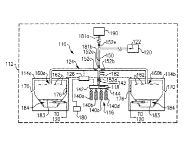
Figure 2 illustrates another embodiment of a fire suppression system 110. In
this disclosure, like reference numerals designate like elements where
appropriate,
and reference numerals with the addition of one-hundred designate modified
elements. The modified elements may incorporate the same features and benefits
of
the corresponding original elements and vice-versa. The fire suppression
system 110
is also implemented in an aircraft 112 but may alternatively be implemented in
other
types of structures.
3
CA 02696397 2010-03-11
The aircraft 112 includes a first cargo bay 114a and a second cargo bay 114b.
The fire suppression system 110 may be used to control fire threats within the
cargo
bays 114a and 114b. In this regard, the fire suppression system 110 includes a
pressurized inert gas source 116 that is configured to provide a first inert
gas output
118, and an inert gas generator 120 configured to provide a second inert gas
output
122. The pressurized inert gas source 116 and the inert gas generator 120 may
also
be regarded as respective high and low pressure inert gas sources. In this
example,
the pressurized inert gas source 116 provides the first inert gas output 118
at a higher
mass flow rate than the second inert gas output 122 from the inert gas
generator 120.
A distribution network 124 is connected with the pressurized inert gas source
116 and the inert gas generator 120 to distribute the first and second inert
gas
outputs 118 and 122 to the cargo bays 114a and 114b. A controller 126 is
operatively connected with at least the distribution network 124 to control
how the
respective first and second inert gas outputs 118 and 122 are distributed. As
described below, the controller 126 may be programmed or provided with
feedback
information to facilitate determining how to distribute the first and second
inert gas
outputs 118 and 122.
The pressurized inert gas source 116 may include a plurality of storage tanks
140a-d. The tanks may be made of lightweight materials to reduce the weight of
the
aircraft 112. Although four storage tanks 140a-d are shown, it is to be
understood
that additional storage tanks or fewer storage tanks may be used in other
implementations. The number of storage tanks 140a-d may depend on the sizes of
the first and second cargo bays 114a and 114b (or other volume zone), leakage
rates
of the volumes zones, ETOPS times, or other factors. Each of the storage tanks
140a-d holds pressurized inert gas, such as nitrogen, helium, argon or a
mixture
thereof. The inert gas may include trace amounts of other gases, such as
carbon
dioxide.
The pressurized inert gas source 116 also includes a manifold 142 connected
between the storage tanks 140a-d and the distribution network 124. The
manifold
142 receives pressurized inert gas from the storage tanks 140a-d and provides
a
volumetric flow through a flow regulator 143 as the first inert gas output 118
to the
distribution network 124. The flow regulator 143 may have a fully open state,
and
4
CA 02696397 2010-03-11 =
intermediate states in between for changing the amount of flow. In this case,
the
flow regulator 143 is an exclusive outlet from the manifold 142 to the
distribution
network, which facilitates controlling the mass flow rate of the first inert
gas output
118.
Each of the storage tanks 140a-d may include a valve 144 that is in
communication with the controller 126 (as represented by the dashed line from
the
controller 126 to the pressurized inert gas source 116). The valves 144 may be
used
to release the flow of the pressurized gas from within the respective storage
tanks
140a-d to the manifold 142. Additionally, the valves 144 may include or
function as
check valves to prevent backflow of pressurized gas into the storage tanks
140a-d.
Alternatively, check valves may be provided separately. Optionally, the valves
bodies 144 may also include pressure and temperature transducers to gauge the
gas
pressure (or optionally, temperature) within the respective storage tanks 140a-
d and
provide the pressure as a feedback to the controller 126 to control the fire
suppression system 110. Pressure and optionally temperature feedback may be
used
to monitor a status (i.e., readiness "prognostics") of the storage tanks 140a-
d,
determine which storage tanks 140a-d to release, determine timing of release,
rate of
discharge or detect if release of one of the storage tanks 140a-d is
inhibited.
The inert gas generator 120 may be a known on-board inert gas generating
system (e.g., "OBIGGS") for providing a flow of inert gas, such as nitrogen
enriched
air, to a fuel tank 190 of the aircraft 112. Nitrogen enriched air includes a
higher
concentration of nitrogen than ambient air. Although OBIGGS is known, the
inert
gas generator 120 in this disclosure is modified via connection within the
distribution network 124 to serve a dual functionality of providing inert gas
to the
fuel tank 190 and facilitating fire suppression.
In general, the inert gas generator 120 receives input air, such as compressed
air from a compressor stage of a gas turbine engine of the aircraft 112 or air
from
one of the cargo bays 114a or 114b compressed by an ancillary compressor, and
separates the nitrogen from the oxygen in the input air to provide an output
that is
enriched in nitrogen compared to the input air. The output nitrogen enriched
air may
be used as the second inert gas output 122. The inert gas generator 120 may
also
utilize input air from a second source, such as cheek air, secondary
compressor air
5
CA 02696397 2010-03-11
from a cargo bay, etc., which may be used to increase capacity on demand. As
an
example, the inert gas generator 120 may be similar to the systems described
in U.S.
Patent No. 7,273,507 or U.S. Patent No. 7,509,968 but are not specifically
limited
thereto.
In the illustrated example, the distribution network 124 includes piping 150
that fluidly connects the cargo bays 114a and 114b with the pressurized inert
gas
source 116 and the inert gas generator 120. The distribution network 124 may
be
modified from the illustrated example for connection with other volume zones.
The distribution network 124 includes a plurality of flow valves 152a-e and
each valve 152a-e is in communication with the controller 126 (as represented
by the
dashed line from the controller 126 to the distribution network 124). The flow
valves
152a-e may be known types of flow/diverter valves and may be selected based
upon
desired flow capability to the cargo bays 114a and 114b. In one example, one
or
more of the flow valves 152a-e are a valve disclosed in U.S. Serial 10/253,
297.
The controller 126 may selectively command the valves 152a-e to open or
close to control distribution of the first and second inert gas outputs 118
and 122.
Additionally, at least the flow valve 152d may be a valve that is biased
toward an
open position (e.g., a fail-open valve) to allow flow of the first inert gas
output 118
in the event that the flow valve 152d is unable to actuate. The distribution
network
124, the flow regulator 143, and the valves 144 may be designed to achieve a
desired
maximum discharge time for discharging all of the inert gas of the storage
tanks
140a-d. In some examples, the discharge time may be approximately two minutes.
Given this description, one of ordinary skill in the art will recognize other
discharge
times to meet their particular needs.
As an example, the flow valves 152a-e may each have an open and closed
state for respectively allowing or blocking flow, depending on whether a fire
threat
is detected. In the absence of a fire threat, the valve 152a may be normally
closed
and valves 152b-e may be normally open. Check valve 181a prevents combustible
vapor from the fuel tank 190 from entering the fire suppression system 110.
Check
valve 181b prevents high pressure from the fire suppression system 110 from
entering the fuel tank 190 inerting piping. Relief valve 182 protects the
inert gas
distribution network 124 and valves 152a-c from overpressure in the event of a
6
CA 02696397 2010-03-11
system failure. Valves 152b and 152c may be either normally open but may close
in
response to a fire threat, or normally closed then opened in response to a
fire threat.
The distribution network 124 also includes an inert gas outlet 160a at the
first cargo bay 114a and an inert gas outlet 160b at the second cargo bay
114b. In
this case, each of the inert gas outlets 160a and 160b may include a plurality
of
orifices 162 for distributing the first inert gas output 118 and/or second
inert gas
output 122 from the distribution network 124.
Each of the first and second cargo bays 114a and 114b may also include an
overboard valve 170 that limits the differential pressure between the interior
of the
cargo bay and the exterior (cheek/bilge). Each cargo bay 114a and 114b may
also
include a floor that separates the bay from a bilge volume below 184. On some
aircraft the floors are not sealed allowing communications of the cargo bay
atmosphere with the bilge atmosphere. These vented type floors may be equipped
with seal members 183 (shown schematically), such as seals, shutters,
inflatable
seals or the like, that cooperate with the controller 126 to seal off the
bilge volume
184 from the bay in response to a fire threat, to limit cargo bay volume and
leakage,
thus minimizing the amount of inert gas required from both inert gas sources
118
and 122.
Each of the cargo bays 114a and 114b may also include at least one oxygen
sensor 176 for detecting an oxygen concentration level within the respective
cargo
bay 114a or 114b. However, in some examples, the fire suppression system may
not
include any oxygen sensors. The oxygen sensors 176 may be in communication
with
the controller 126 and send a signal that represents the oxygen concentration
to the
controller 126 as feedback. The inert gas generator 120 may also include one
or
more oxygen sensors (not shown) for providing the controller 126 with a
feedback
signal representing an oxygen concentration of the nitrogen enriched air. The
cargo
bays 114a and 114b may also include temperature sensors (not shown) for
providing
temperature feedback signals to the controller 126.
The controller 126 of the fire suppression system 110 may be in
communication with other onboard controllers or warning systems 180 such as a
main controller or multiple distributed controllers of the aircraft 112, and a
controller (not shown) of the inert gas generator 120. For instance, the other
7
CA 02696397 2010-03-11
controllers or warning systems 180 may be in communication with other systems
of
the aircraft 112, including a fire threat detection system for detecting a
fire threat
within the cargo bays 114a and 114b and issuing a fire threat signal in
response to a
detected fire threat or for the purpose of testing, evaluating, or certifying
the fire
suppression system 110.
The controller 126 may communicate with the controller of the inert gas
generator 120 to control which input air source the inert gas generator 120
draws
input air from and/or adjust the flow rate and oxygen concentration of the
second
inert gas output 122. For instance, the controller 126 may command the inert
gas
generator 120 to draw air from one of the cargo bays 114a or 114b where there
is no
fire threat or control where the inert gas generator 120 draws the input air
from
based on the flight cycle of the aircraft 112. Additionally, the controller
126 may
adjust the oxygen concentration and/or flow rate of the second inert gas
output 122
in response to a detected oxygen concentration in a volume zone where a fire
threat
occurs or in response to the flight cycle of the aircraft 112.
The following example supposes a fire threat within the first cargo bay 114a.
The other on board controller or warning system 180 may detect the fire threat
in the
cargo bay 114a in a known manner, such as by smoke detection, video,
temperature,
flame detection, detection of combustion gas, or any other known or
appropriate
method of fire threat determination. Determination of the fire threat may be
related
to a predetermined threshold or rate increase of smoke, temperature, flame
detection,
combustion gas detection, or other characteristic.
In response to the fire threat, the controller 126, other on board controller
or
warning system 180 or both may shut down an air management/ventilation system
prior to using the fire suppression system 110. The controller 126 may
determine the
timing for shutting off the air management/ventilation system, depending on
received feedback information. In the absence of a fire threat, the air
management/ventilation system may ventilate the cargo bays 114a and 114b.
However, in a fire threat situation, reducing ventilation facilitates
containing the fire
threat.
The controller 126, which is programmed with the volume of the cargo bay
114a and other information, intelligently releases the first inert gas output
118. The
8
CA 02696397 2010-03-11
controller 126 initially causes the release of the first inert gas output 118
from a
required number of pressurized inert gas source 116 based on the known volume
of
the cargo bay 114a to reduce an oxygen concentration of the fire threat in the
cargo
bay 114a below a predetermined threshold. As an example, the predetermined
threshold may be 12%. In this regard, the controller 126 may control how the
first
inert gas output 118 is distributed to the cargo bay 114a. For instance, an
objective
of using the controller 126 is to control distribution of the first and second
inert gas
outputs 118 and 122 to effectively control the fire threat while limiting
overpressure
of the cargo bay 114a and gas turbulence in the cargo bay 114a. The
displacement of
the atmosphere of the cargo bay 114a may also provide the benefit of cooling
the
cargo bay 114a and further contribute to fire threat suppression and aircraft
structure
protection.
The controller 126 is pre-programmed with the volumes of the cargo bay
114a, 114b etc, in addition to other information (such as the volume that one
storage
tank can protect), to enable the controller 126 to determine how to distribute
the first
inert gas output 118. As an example, cargo bay 114a may require four storage
tanks
of first inert gas output 118, whereas cargo bay 114b may require only three.
The
controller 126 will open the required number of valves 144 to discharge the
correct
quantity of gas, and to the correct location. Furthermore, the controller 126
may
limit the mass flow rate based on the smaller volume of the cargo bay 114b by
sequentially opening valves 144 to avoid over pressurization of the cargo bay
114b.
The controller 126 may also release multiple storage tanks 140a-d to ensure
adequate mass flow of the first inert gas output 118 to the cargo bay 114a.
For
instance, feedback to the controller 126 may indicate that a previously
selected inert
gas source 116 is not discharging at the expected rate. In this case, the
controller 126
may release another of the storage tanks 140a-d to provide a desired mass flow
rate,
such as to reduce the oxygen concentration below the predetermined threshold.
The controller 126 may also cause the flow valve 152d to release pulses of
the first inert gas output 118. For instance, feedback to the controller may
indicate
that additional inert gas is needed to maintain the desired oxygen
concentration. In
this case, the controller 126 may provide pulses to flow valve 152d.The pulses
are
intended to maintain the oxygen concentration at the maximum concentration
level
9
CA 02696397 2010-03-11
acceptable without consuming excessive amounts of stored inert gas. This mode
of
operation may be used during a descent in a flight cycle.
Additionally, the controller 126 may be programmed to respond to
malfunctions within the fire suppression system 110. For instance, if one of
the
valves 152a-e or valves 144 malfunctions, the controller 126 may respond by
opening or closing other valves 152a-e or 144 to change how the first or
second inert
gas outputs 118 or 122 are distributed.
In some examples, the storage tank pressure provided as feedback to the
controller 126 from the pressure transducers of the valves 144 permits the
controller
126 to determine when a storage tank 140a-d is nearing an empty state. In this
regard, as the pressure in any one of the storage tanks 140a-d depletes, the
controller
126 may release another of the storage tanks 140a-d to facilitate controlling
the mass
flow rate of the first inert gas output 118 to the cargo bay 114a. The
controller 126
may also utilize the pressure and temperature feedback in combination with
known
information about the flight cycle of the aircraft 112 to determine a future
time for
maintenance on the storage tanks 140a-d, such as to replace the tanks. For
instance,
the controller 126 may detect a slow leak of gas from one of the storage tanks
140a-
d and, by calculating a leak rate, establish a future time for replacement
that does is
convenient in the utilization cycle of the aircraft 112 and that occurs before
the
pressure depletes to a level that is deemed to be too low.
Once a predetermined amount of gas from the first inert gas output 118
reduces the oxygen concentration below the 12% threshold, the controller 126
subsequently releases the second inert gas output 122 from the inert gas
generator
120. The controller 126 may reduce or completely cease distribution of the
first inert
gas output 118 in conjunction with releasing the second inert gas output 122.
In this
case, the second inert gas output 122 normally flows to the fuel tank 190.
However,
the controller 126 diverts the flow within the distribution network 124 to the
cargo
bay 114a in response to the fire threat. For example, the controller 126
closes flow
valves 152b, and 152e, and opens flow valve 152a to distribute the second
inert gas
output 122 to the cargo bay 114a.
The second inert gas output 122 is lower pressure than the pressurized the
first inert gas output 118 and is fed at a lower mass flow rate than the first
inert gas
CA 02696397 2010-03-11
output 118. The lower mass flow rate is intended to maintain the oxygen
concentration below the 12% threshold. That is, the first inert gas output 118
rapidly
reduces the oxygen concentration and the second inert gas output 122 maintains
the
oxygen concentration below 12%. In this way, fire suppression system 110 uses
the
renewable inert gas of inert gas generator 120 to conserve the finite amount
of high
pressure inert gas of the pressurized inert gas source 116.
In some examples, if the capacity of the inert gas generator 120 exceeds the
amount of the second inert gas output 122 used to maintain the oxygen
concentration
below the threshold, the controller 126 may use the additional capacity to
replenish
at least a portion of the inert gas of the storage tanks 140a-d using an
ancillary high
pressure compressor or the like. For instance, the additional capacity inert
gas may
be diverted from the inert gas generator 120, pressurized, and routed to the
storage
tanks 140a-d.
If, at some point in a flight profile, the oxygen concentration in the OBIGGS
output rises above the predetermined threshold while supplying the second
inert gas
output 122, the controller 126 may communicate with the OBIGGS controller on
the
second inert gas output 122 to adjust the output to ensure that the NEA
supplied is
not diluting the required inert atmosphere and then release additional first
inert gas
output 118 to again maintain the oxygen concentration below the threshold. In
some
examples, releasing additional first inert gas output 118 may be triggered
when the
oxygen concentration begins to approach the predetermined threshold, or when a
rate of increase of the oxygen concentration exceeds a rate threshold. In some
cases,
the controller 126 may release pulses of the first inert gas output 118 to
assist the
second inert gas output 122 in keeping the oxygen concentration below the
threshold. The pulses, or even a continuous flow, of the first inert gas
output 118
may be provided at the lower mass flow rate of the second inert gas output
122, or at
some intermediate mass flow rate. In this regard, if one of the storage tanks
140a-d
is near empty, the remaining inert gas in the storage tank, which is at a
relatively low
pressure, may be used. Alternatively, an additional source of inert gas may be
provided to assist the second inert gas output 122 in keeping the oxygen
concentration below the threshold.
11
CA 02696397 2010-03-11
Figure 3 illustrates a schematic diagram of the controller 126 and exemplary
inputs and outputs that the controller 126 may use to operate the fire
suppression
system 110. For instance, the controller 126 may receive as inputs a master
alarm
signal from the other on board controller or warning system 180, the status of
the
storage tanks 140a-d (e.g., gas pressures), signals representing the status of
the air
management/ventilation system, signals representing the oxygen concentration
from
the oxygen sensor 176, and signals representing the oxygen concentration of
the
second inert gas output 122 from the inert gas generator 120. The outputs may
be
responses to the received inputs. For instance, in response to a fire threat
in one of
the cargo bays 114a or 114b, the controller 126 may designate the respective
cargo
bay 114a or 114b as a hazard zone and divert flow of the first inert gas
output 118 to
the designated hazard zone. Additionally, the controller 126 may designate the
number of storage tanks 140a-d to be released to address the fire threat. The
controller 126 may also determine a timing to release the storage tanks 140a-
d. For
instance, the controller 126 may receive feedback signals representing oxygen
concentration, temperature, or other inputs that may be used to determine the
effectiveness of fire suppression and subsequently the timing for releasing
the
storage tanks 140a-d.
The controller 126 may also use the inputs to determine a sequential release
of the storage tanks 140a-d to suppress a fire threat and control mass flow
rate of the
first inert gas output 118 to avoid over pressurization. However, if over
pressurization occurs relative to a predetermined pressure threshold, the
overboard
valves 170 may release pressure. Controlling the mass flow rates of the first
inert gas
output 118 to avoid or limit over pressurization may also enable use of
smaller size
overboard valves 170.
The fire suppression system 110 may also be tested and certified to
determine whether the fire suppression system 110 meets desired criterion. For
example, the fire suppression system 110 may be tested under predetermined, no
fire
threat conditions, such as when the aircraft 112 is grounded and at a desired
atmospheric pressure (e.g., sea level), flying at altitude, or in a descent
phase of the
flight cycle. As an example, the fire threat signal may be manually activated
to
trigger the fire suppression system 110 under predetermined conditions.
12
CA 02696397 2010-03-11
In one example, the fire suppression system 110 is activated with empty
cargo bays 114a and 114b such that the first inert gas output 118 releases
into one of
the cargo bays 114a or 114b. The fire suppression system 110 may reach and
sustain
an oxygen concentration or 12% or lower vol./vol. at sea level in the selected
cargo
bay 114a or 114b in less than two minutes. This test may be conducted for each
volume zone that is intended to be protected using the fire suppression system
110
In another example, the fire suppression system 110 is activated with the
aircraft 112 at altitude and with empty cargo bays 114a and 114b such that the
first
inert gas output 118 releases into one of the cargo bays 114a or 114b. The
fire
suppression system 110 may reach and sustain an oxygen concentration or 12% or
lower vol./vol. in the selected cargo bay 114a or 114b. The second inert gas
output
122 is released as needed to sustain a 12% oxygen concentration vol./vol. or
lower
during worst case flight altitude and ventilation conditions. This test may be
conducted sequentially with a descent test or separately and may be conducted
for
each volume zone that is intended to be protected using the fire suppression
system
110
In another example, the fire suppression system 110 is activated with the
aircraft 112 in a cruise portion of the flight cycle and with empty cargo bays
114a
and 114b such that the first inert gas output 118 releases into one of the
cargo bays
114a or 114b. The fire suppression system 110 may reach and sustain an oxygen
concentration or 12% or lower vol./vol. in the selected cargo bay 114a or
114b. The
second inert gas output 122 is released as needed to sustain a 12% oxygen
concentration vol./vol. or lower during worst case flight altitude and
ventilation
conditions. The aircraft is then placed in the worst case decent phase of
flight. If
necessary supplemental first inert gas output 118 maybe required to sustain
the
required 12% or below oxygen concentration. This test may be conducted
sequentially with the altitude test or separately and may be conducted for
each
volume zone that is intended to be protected using the fire suppression system
110.
Although a combination of features is shown in the illustrated examples, not
all of them need to be combined to realize the benefits of various embodiments
of
this disclosure. In other words, a system designed according to an embodiment
of
this disclosure will not necessarily include all of the features shown in any
one of the
13
CA 02696397 2012-04-02
Figures or all of the portions schematically shown in the Figures. Moreover,
selected
features of one example embodiment may be combined with selected features of
other
example embodiments.
The preceding description is exemplary rather than limiting in nature.
Variations and
modifications to the disclosed examples will become apparent to those skilled
in the art. The
scope of legal protection given to this disclosure can be determined by
studying the
following claims.
14