Note: Descriptions are shown in the official language in which they were submitted.
CA 02696659 2010-03-09
CENTER CINCH AND
RELEASE OF BUTTRESS MATERIAL
BACKGROUND
1. Technical field
The present disclosure relates to an anvil assembly incorporating a strip of
buttress
material for use with a surgical stapling instrument. More particularly, the
present disclosure
relates to a buttress release mechanism for release of the buttress material
from the surgical
stapling instrument after stapling.
2. Background Of Related Art
During various surgical procedures it is often necessary to join two sides of
tissue. This
is typically accomplished by approximating two edges of the tissues flush
against one another
and securing them by stapling, suturing, etc. In some instances, the staple or
suture line
connecting the tissues may tear or tend to pull through the tissues,
particularly, where the
tissues are diseased and relatively weak. Additionally, during healing,
leakage may occur
through the staple or suture lines.
In order to alleviate these problems, a strip of material, called "buttress
material" is
positioned against the tissues prior to stapling or suturing. The buttress
material tends to
reinforce the staple or suture line as well as tend to prevent leakage prior
to healing.
The buttress material may be attached to the surgical instrument being used.
For
example, the buttress material is often pre-attached to a staple cartridge or
anvil assembly of a
surgical stapling instrument. The attachment of the buttress material needs be
sufficiently
secure to allow the surgical instrument to be inserted into the body of a
patient as well as
allowing the staple cartridge and anvil to be positioned about specific
tissues to be stapled.
- 1 -
CA 02696659 2010-03-09
Furthermore, after stapling of the tissues, the buttress material needs to be
attached in a
manner which allows easy separation of the buttress material from the
associated staple
cartridge and/or anvil.
Therefore, it is desirable to provide a cartridge or anvil assembly which is
capable of
easily releasing the buttress material after tissues have been stapled.
SUMMARY
There is disclosed a buttressed anvil assembly for use with a surgical
stapling
instrument. The buttressed anvil assembly generally includes an anvil having a
strip of buttress
material positioned adjacent a bottom side of the anvil. Distal and proximal
sutures secure the
buttress material to the anvil. A tensioning mechanism is provided at a distal
end of the anvil
assembly. The tensioning mechanism includes a cinch track engageable with the
distal suture
to hold a distal end of the strip of buttress material against the anvil. The
cinch track is movable
between a first vertical position tensioning the distal suture against the
strip of buttress material
to a second vertical position releasing tension on the distal suture to allow
release of the strip of
buttress material from the anvil.
A release member is provided in the anvil to move the cinch track between the
first
vertical position and the second vertical position. The release member
includes a wedge
engageable within a slot formed in the cinch track. A wedge is movable between
a first
horizontal position maintaining the cinch track in the first vertical position
and a second
horizontal position allowing the cinch track to move to the second vertical
position. A proximal
suture may also be provided to secure a proximal end of the strip of buttress
material to a
proximal end of the anvil.
Specifically, in a particular embodiment, the anvil assembly generally
includes an anvil
member having a first side and a second side and a length of suture material
passing from the
- 2 -
CA 02696659 2010-03-09
first side of the anvil member to the second side of the anvil member. A cinch
track is movably
mounted on the first side of the anvil member and is engageable with the
length of suture. The
cinch track is movable between a first vertical position tensioning the length
of suture and a
second vertical position releasing tension on the length of suture. A release
member is movably
mounted on the first side of the anvil member and is movable relative to the
cinch track between
a first horizontal position and a second horizontal position. The release
member maintains the
cinch track in the first vertical position when the release member is in the
first horizontal position
and allows the cinch track to move to the second vertical position when the
release member is
in the second horizontal position.
The anvil assembly additionally includes a strip of buttress material
positioned adjacent
the second side of the anvil member.The length of suture includes a backspan
and first and
second suture sides extending from the backspan. The backspan is engageable
with the strip
of buttress material to maintain the strip of buttress material adjacent the
second side of the
anvil member when the cinch track is in the first vertical position.
The anvil member includes first and second holes extending between the first
and
second sides of the anvil member. The first side of the length of suture
material extends
through the first hole and the second side of the suture material extends
through the second
hole. The cinch track includes a first track and the first suture side is
secured in the first track.
The cinch track also includes a second track and the second suture side is
secured in the
second track.
The release member includes a wedge and the cinch track includes a slot such
that the
cinch track is in the first vertical position when the wedge is positioned
within the slot and is in
the second vertical position when the wedge is out of the slot. The anvil
member includes a
longitudinally extending slot and the release member includes a guide rib
movable within the
longitudinally extending slot.
- 3 -
CA 02696659 2010-03-09
The strip of buttress material includes a perforation line adjacent a distal
end of the
buttress material to allow separation of the buttress material distally of the
anvil slot. The strip
of buttress material includes first and second cutouts to accommodate passage
of the first and
second sides of the length of suture material.
The anvil assembly additionally includes a proximal length of suture material
for securing
a proximal end of the strip of buttress material to the anvil member. The
proximal length of
suture material includes a backspan and first and second sides extending from
the backspan.
The backspan secures a proximal end of the strip of buttress material to the
second side of the
anvil member. The anvil member includes a pair of slots adjacent the proximal
end of the anvil
member. The pair of slots is dimensioned to frictionally secure the first and
second sides of the
proximal length of suture material. The strip of buttress material includes
first and second
cutouts formed adjacent the proximal end of the strip of buttress material for
passage of the first
and second sides of the proximal length of suture material.
The anvil assembly further includes a cover affixed to the anvil member. The
cover
including a distal window providing visualization of the cinch track and a
pair of proximal
windows providing visualization of the first and second sides of the proximal
length of suture
material secured within the first and second slots formed in the anvil member.
DESCRIPTION OF THE DRAWINGS
An embodiment of the presently disclosed buttressed anvil assembly is
disclosed herein
with reference to the drawings, wherein:
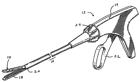
FIG. 1 is a perspective view of a surgical stapling instrument incorporating a
buttressed
anvil assembly;
FIG. 2 is a perspective view, with parts separated, of the buttressed anvil
assembly
incorporating a strip of buttress material;
- 4 -
1
CA 02696659 2010-03-09
FIG. 3 is a perspective view of a cinch track and release bar of the
buttressed anvil
assembly;
FIG. 3a is a side view, partially shown in section, taken along the line 3a-3a
of FIG. 3;
FIG. 4 is a perspective view of the distal end of the buttressed anvil
assembly taken from
the top;
FIG. 5 is a perspective view of the distal end of the buttressed anvil
assembly taken from
the bottom;
FIG. 6 is a perspective view similar to FIG. 4 with an anvil cover removed;
FIG. 7 is a side view of the distal end of the buttressed anvil assembly with
the anvil
cover removed;
FIG. 8 is a side view similar to FIG. 7 during the initial advancement of a
knife bar toward
the release bar;
FIG. 9 is a side view similar to FIG. 8 illustrating the engagement of the
knife bar with the
release bar; and
FIG. 10 is a side view similar to FIG. 8 illustrating the knife bar advancing
the release bar
through the cinch track to release tension on the strip of buttress material.
- 5 -
i
CA 02696659 2016-05-04
DETAILED DESCRIPTION OF EMBODIMENTS
An embodiment of the presently disclosed buttressed anvil assembly will now be
described in detail with reference to the drawings wherein like numerals
designate identical or
corresponding elements in each of the several views. As is common in the art,
the term
'proximal' refers to that part or component closer to the user or operator,
i.e. surgeon or
physician, while the term "distal" refers to that part or component further
away from the user.
Referring to FIG. 1, there is disclosed a buttressed anvil assembly or anvil
assembly 10
for use with a surgical stapling instrument 12. As used herein, "buttress"
includes pledgets,
staple line reinforcement material, gaskets, and other materials used in
conjunction with surgical
instruments for joining tissue. Surgical stapling instrument 12 is a type well
known in the art and
is embodied in U.S. Patent Nos. 5,762,256; 5,782,396; and 6,032,849,
Surgical stapling instrument 12 generally includes a pistol grip body portion
14 having an
elongate tubular member 16 extending distally from body portion 14. A staple
cartridge 18 is
mounted on a distal end 20 of elongate tubular member 16. Anvil assembly 10 is
movably
mounted on a distal end 20 of elongate tubular member 16 and is movable
between an open
position spaced apart from staple cartridge 18 to a closed position wherein
anvil assembly 10 is
in close cooperative alignment with staple cartridge 18.
In order to move anvil assembly 10 between the open and closed positions,
surgical
stapling instrument 12 includes a trigger 22 pivotally mounted to body portion
14. Trigger 22
controls the linear movement of an actuation shaft (not shown) which is
mounted within the
elongated tubular member 16. The actuation shaft operates to move a drive beam
(not shown)
distally to initially move the anvil assembly 10 between the open and closed
positions. The
drive beam also acts to move an actuation sled (not shown) distally through
the staple cartridge
18 to eject staples. The drive beam includes a knife blade to cut tissue as
the drive beam
- 6 -
CA 02696659 2016-05-04
translates through the staple cartridge 18. A rotation knob 24 is provided to
orient anvil
assembly 10 and staple cartridge 18 relative to the tissue being stapled.
Although surgical stapling instrument 12 is shown with a single trigger 22
which
accomplishes both jaw closure and firing of staples, it is further
contemplated that the present
buttress release mechanism can also be used with surgical stapling instruments
of the type
which utilize a clamping mechanism to close the jaws which is separate from
the firing
mechanism. See, for example, U.S. Patent No. 5,476,206.
Referring now to FIG. 2, anvil assembly 10 generally includes an anvil member
26,
having a knife slot 28 extending longitudinally partially through anvil member
26, and a length or
strip of buttress material 30. Strip of buttress material 30 is secured to
anvil member 26 by a
first or distal suture 32 and a second or proximal suture 34. Distal and
proximal sutures 32 and
34 secure respective distal and proximal ends 36 and 38 of buttress material
30 to anvil
member 26 in a manner described in more detail hereinbelow.
Buttress material 30 further includes a pair of distal cutouts 40 and 42
formed adjacent
distal end 36 of buttress material 30. Distal cutouts 40 and 42 are provided
to accommodate
passage of distal suture 32 to secure buttress material 30 to anvil member 26
and prevent any
distal movement of buttress material 30 relative to anvil member 26.
Similarly, a pair of
proximal cutouts 44 and 46 is formed adjacent proximal end 38 of buttress
material 30. Proximal
cutouts 44 and 46 are provided to receive proximal suture 34 to secure
proximal end 38 of
buttress material 30 to anvil member 26 and prevent any longitudinal motion of
buttress material
30. It should be noted that, during stapling and cutting of tissue, distal end
36 of buttress
material 30 is distal of knife slot 28 and thus is not cut. A perforation line
48 may be formed in
distal end 36 to facilitate separation of buttress material 30 into two halves
after tissue has been
stapled and cut.
- 7 -
CA 02696659 2010-03-09
In order to maintain tension of distal suture 32 against buttress material 30
prior to the
cutting of tissue and to allow for the release of tension of distal suture 32
against buttress
material 30, anvil assembly 10 further includes a cinch track 50 which is
positioned within a
distal end 52 of anvil member 26. Cinch track 50 is movable between a first
vertical position
tensioning distal suture 32 against buttress material 30 and a second vertical
position releasing
tension of distal suture 32 against buttress material 30. Cinch track 50 is
provided to securely
engage first and second sides 54 and 56 of first suture 32. The suture can be
preformed in a
shape defining the first side 54, second side 56, and backspan 58, or can
comprise an ordinary
suture that is wrapped around the anvil so as to defining the first side 54,
second side 56, and
backspan 58. The backspan 58 of first suture 32 lies against the distal end 36
of buttress
material 30 against anvil member 26.
In order to move cinch track 50 between the first and second vertical
positions, a release
member 60 is provided and is longitudinally or horizontally movable within
anvil member 26 in a
manner described in more detail hereinbelow. The release member 60 may be
formed as a bar,
rod, cable or other member.
As shown, knife slot 28 has a proximal end 62 which is open at proximal end 64
of anvil
member 26. A distal end 66 of knife slot 28 terminates proximally of distal
end 52 of anvil
member 26. As noted herein above, buttress material 30 includes a perforation
line 48 to
facilitate separation of distal end 36 of buttress material 30 as it is
located distally of distal end
66 of knife slot 28.
In order to secure a proximal end 38 of buttress material 30 against anvil
member 26,
anvil member 26 is provided with a pair of slots 68 and 70 which are
configured to securely
receive first and second sides 72 and 74 of proximal suture 34. The proximal
suture can be
preformed in a shape or comprise an ordinary suture wrapped around the anvil
member so as to
define first side 72, second side 74 and backspan 76. The backspan 76 of
proximal suture 34
- 8 -
CA 02696659 2010-03-09
engages proximal end 38 of buttress material 30 to secure proximal end 38
against anvil
member 26.
Anvil assembly 10 additionally includes an anvil cover 78 having a distal
cinch window
80 formed in a distal end 82 of anvil cover 78. Distal cinch window 80 is
provided to allow the
surgeon to visually confirm the engagement of distal suture 32 with cinch
track 50. A pair of
proximal cinch windows 84 and 86 are provided adjacent proximal end 88 of
anvil cover 78 and
serve to allow the surgeon to visually confirm the engagement of proximal
suture 34, specifically
the engagement of first and second sides 72 and 74, with slots 68 and 70
formed in proximal
end 64 of anvil member 26.
Anvil cover 78 includes longitudinally extending side cuts 90 and 92 which are
configured to engage side walls 94 and 96, formed in anvil member 26, in
friction fit fashion to
secure anvil cover 78 to anvil member 26. Alternatively, the anvil cover may
be attached using
welding, adhesives or other means. Mounting structure 98 is provided on
proximal end 88 to
facilitate attachment of anvil assembly 10 to distal end 20 of elongate
tubular member 16 (FIG.
1).
The cinch track generally includes a body portion defining one or more tracks.
Referring
now to FIGS. 3 and 3a, cinch track 50 has a body portion 100 with first and
second tracks 102
and 104. First and second tracks 102 and 104 are dimensioned to pinch or cinch
first and
second sides 54 and 56, respectively, of suture 32 to secure suture 32 to
cinch track 50. Body
portion 100 additionally includes a center slot 106 for receipt of release
member 60 in a matter
discussed in more detail hereinbelow.
As noted herein above, cinch track 50 is positioned within distal end 52 of
anvil member
26 and is movable between first and second vertical positions relative to
anvil member 26. As
specifically shown in FIG. 3, a pair of distal arms 108 and 110 extend
distally from body portion
100 while proximal tabs 112 and 114 extend proximally from body portion 100.
Distal arms 108
and 110 are positioned against a proximal face 116 formed in distal end 52 of
anvil member 26
- 9 -
CA 02696659 2010-03-09
(FIG. 2). Likewise, proximal tab 112 and proximal tab 114 are configured to
loosely engage
distal ends 118 and 120 of side walls 94 and 96 formed in anvil member 26
allowing cinch track
50 to move vertically within distal end 52 of anvil member 26 (FIG. 2).
Referring back for the moment to FIG. 2, as noted herein above, release member
60 is
provided to move cinch track 50 between the first and second vertical
positions. Release
member 60 includes a distal wedge 122 which is configured to ride within
center slot 106 of
cinch track 50 to move cinch track 50 between the first and second vertical
positions. A sloped
face 124 extends proximally from distal wedge 122. Sides 126 and 128 of distal
wedge 122
facilitate guiding distal wedge 122 against cinch track 50. In the embodiment
of FIG. 3a, the
bottom surface of the cinch track 50 is generally horizontal. However, in
other embodiments,
one or more surfaces can be shaped to cooperate with the sloped face 124, such
as a cam
surface, and may correspond to the shape of the sloped face 124.
Referring now to FIG. 3, release member 60 further includes a guide bar 130
extending
proximally from distal wedge 122. Guide bar 130 includes a central portion 132
and a
proximally extending flanged portion 134. Flanged portion 134 helps align
release bar 60 within
side walls 94 and 96 of anvil member 26. As shown, a guide rib 136 extends
downwardly from
guide bar 130 and is configured to ride within knife slot 28 such that release
member 60 is
movable in a longitudinal or horizontal direction relative to cinch track 50.
With specific reference to FIG. 3a, it can be seen that wedge 122 of release
member 60
is configured to move body portion 100 of cinch track 50 vertically. Sloped
face 124 of release
member 60 facilitates assembly of anvil assembly 10, and specifically, allows
for reset of
release member 60 to pre-fire and assembly condition. A base stop 138 is
provided on distal
wedge 122 of release member 62 to prevent pulling wedge 122 completely through
center slot
106 of cinch track 50 during assembly.
Referring now to FIGS. 2-7, and initially with regard to FIG. 2, the assembly
of a strip of
buttress material 30 to anvil member 26 will now be described. Proximal end 38
of strip of
-10-
CA 02696659 2010-03-09
buttress material 30 is secured to proximal end 64 of anvil member 26.
Specifically, proximal
end 38 is positioned against an underside 140 of anvil member 26. Proximal
suture 34 is
manipulated such that first and second free ends 142 and 144 of first and
second sides 72 and
74 pass through cutouts 44 and 46 to bring backspan 76 of proximal suture 34
into engagement
with proximal end 38 of strip of buttress material 30.
Thereafter, first and second sides 72 and 74 are positioned within slots 68
and 70 in
anvil member 26. During positioning, first and second side 72 and 74 are
tensioned so as to
secure proximal end 38 of strip of suture material 30 against underside 140 of
anvil member 26.
As noted herein above, slots 68 and 70 are dimensioned so as to pinch or cinch
first and
second sides 72 and 74. Once strip of suture material 30 has been secured, the
excess
material of first and second side 72 and 74 extending beyond slots 68 and 70
may be trimmed
off through the cover. It should be noted that, since proximal end 38 of strip
of suture material
30 stretches across knife slot 28, there is no need to release the tension on
proximal suture 34
as it will be cut by a knife blade (not shown) during the stapling procedure.
[[the knife blade will
be described, as noted above]]
With reference to FIGS. 2-7, the assembly of distal end 36 of strip of suture
material 30
to anvil member 26 will now be described. Initially, with respect to FIGS. 3
and 3a, release
member 60 is in a first or proximal most position. Cinch track 50 is in a
first or vertically highest
most position due to the passage and engagement of wedge 122 of release member
60 within
slot 106 formed in body portion 100 of cinch track 50.
With reference to FIG. 2, distal end 36 of strip of buttress material 30 is
positioned flush
against underside 140 of anvil member 26. Distal suture 32 is manipulated such
that free ends
146 and 148 of first and second sides 54 and 56, respectively, passed through
cutouts 40 and
42 formed in distal end 36 of strip of buttress material 30. As shown, distal
end 52 of anvil
member 26 is provided with a pair of spaced apart holes 150 and 152. Free ends
146 and 148
of distal suture 32 are passed through holes 150 and 152 such that first and
second sides 54
- 11 -
CA 02696659 2010-03-09
and 56 are aligned alongside first and second tracks 102 and 104 of cinch
track 50. Vertical
tension is applied to free ends 146 and 148 to secure distal end 36 of strip a
buttress material
30 against underside 140 of anvil member 26.
First and second sides 54 and 56 are then manipulated such that first side 54
passes
within second track 104 and second side 56 passes within first track 102 (see
also FIGS. 6 and
7). As noted herein above, first and second tracks 102 and 104 are dimensioned
so as to pinch
or cinch a suture positioned therein. Thereafter, excess material of first and
second sides 54
and 56 of distal suture 32 may be trimmed off. Finally, cover 78 is affixed to
anvil member 26 in
the manner described herein above.
With reference to FIGS. 4 and 5, in the assembled condition, first and second
sides 54
and 56 of distal suture 32 are visible through distal cinch window 80 in cover
78 for verification
(FIG. 4). Likewise, backspan 58 of distal suture 32 can be confirmed as
extending across
perforation line 48 and strip of suture material 30 (FIG. 5).
Referring now to FIGS. 1 and 6-10, the use of anvil assembly 10 will now be
described.
With reference to FIGS. 6 and 7, and as described herein above, in the initial
position release
bar 60 is in a first or proximal most position maintaining cinch track 50 in a
first or vertically -
highest position relative to anvil member 26 thereby maintaining tension of
backspan 58 of distal
suture 32 against distal end 36 of strip of buttress material 30.
In use, with reference to FIG. 1, surgical stapling instrument 12 is
manipulated such that
anvil assembly 10 and staple cartridge 18 are positioned about the tissue (not
shown) to be
stapled. Once surgical stapling 12 has been properly positioned, trigger 22 is
actuated to move
anvil assembly 10 to the closed position about tissue relative to staple
cartridge 18. While not
specifically shown, anvil pockets are provided on anvil member 26 to clinch
staples ejected out
of staple cartridge 18 through the subject tissue and through strip of
buttress material 30.
Referring back for the moment to FIG. 2, and as noted herein above, backspan
76 of
proximal suture 34 extends across knife slot 28. Referring now to FIG. 8, a
knife bar 154 is
- 12-
CA 02696659 2010-03-09
associated with surgical stapling instrument 12 to cut through staple lines
formed in the tissue
by staple cartridge 18 and anvil assembly 10. As knife bar 154 passes distally
through knife slot
28 a blade 156 of knife bar 154 cuts through proximal end 38 of strip of
buttress material 30 and
severs backspan 76 a proximal suture 34. Continued advancement of knife bar
154 distally
through slot 28, causes blade 156 to continue to cut through strip of buttress
material 30.
With continued reference to FIG. 8, as knife bar 154 advances distally through
anvil
member 26, a distal top edge 158 of knife bar 154 approaches a proximal edge
160 of release
member 60. As best shown in FIG. 9, as distal edge 158 of knife bar 154 moves
distally it
engages proximal edge 160 of release member 60, knife bar 154 begins to drive
release
member 60 distally such that distal wedge 122 of release member 60 is driven
distally through
slot 106 (FIGS. 2 and 3) formed in cinch track 50.
With specific reference to FIG. 10, as release member 60 is driven to a second
or distal
most position by a knife bar 54, sloped face 124 of distal wedge 122 clears
slot 106 allowing
cinch track 50 to drop down to a second or vertically lowest most position
relative to anvil
member 26. As shown, when cinch track 50 is in the second or vertically lowest
position,
tension is released on distal suture 32 such that backspan 58 of distal suture
32 drops a
substantial distance below underside 140 of anvil member 26. This creates an
opening or gap
162 between backspan 58 of distal suture 32 and underside 140 of anvil member
26.
Once knife bar 154 has reached a distal most position, pressure on trigger 22
may be
released allowing anvil member 10 to move to the open position relative to
staple cartridge 18
(FIG. 1). As anvil assembly 10 is moved to the open position, distal end 36 of
strip of buttress
material 30, being stapled the tissue, pulls free through gap 162 allowing
distal end 36 to
separate from anvil member 26. As noted herein above, and as shown in FIG. 2,
perforation
line 48 is formed in distal end 36 of strip of buttress material 30 allowing
strip of buttress
material 30 to separate into halves generally along the cut line formed by
knife blade 156
through strip of buttress material 30. In this manner, anvil assembly 10
allows for simple and
-13-
CA 02696659 2016-05-04
easy assembly of a strip of buttress material 30 to with anvil member 26 and,
more importantly,
allows for easy release of distal end 36 of a strip of buttress material 30
from anvil member 26.
It will be understood that various modifications may be made to the
embodiments
disclosed herein. For example, the release member could be arranged to be
pulled proximally
to change the position of the cinch track and release the suture and buttress.
In other
embodiments, the proximally pulled release member, or the release member 60
discussed
above, may be connected to a separate actuator on the handle of the surgical
instrument, for
engagement by the user of the instrument. In another example, the disclosed
cinch track may
have more or fewer tracks to accommodate more or fewer wraps of a length of
suture material.
Further, the disclosed tensioning mechanisms, including the suture track and
the release bar,
may be adapted to be incorporated in a staple cartridge and to function with
driving bars In the
staple cartridge. Additionally, the disclosed methods and structure for
releasing tension on a
suture maintaining a strip of buttress material may find use in other forms of
surgical staplers
such as, for example, circular staplers, etc. In further embodiments, a
release member pushes
cinch track down vertically to release the tension on the suture and release
the buttress.
Therefore, the above description should not be construed as limiting, but
merely as
exemplifications of particular embodiments. Those skilled in the art will
envision other
modifications within the scope of the claims appended hereto.
- 14-