Note: Descriptions are shown in the official language in which they were submitted.
02/17/2010 03 : 26 PM CA 02696672 2010-02-17
Page: 6
A ramp assembly for mobile shelving
The present invention relates to a ramp assembly for mobile shelving and, in
particular,
to a ramp assembly including ramp sections adapted to be rotatably snap fit to
a mobile shelving
track. The ramp pivot geometry is designed to be unobtrusive, and allows
removal and refitting
of ramps without having to lift or up-end the track.
BACKGROUND OF THE INVENTION
Mobile shelving systetns typically comprise a plurality of shelving units
which are
equipped with rollers to traverse along spaced apart tracks, each individual
shelf unit being a tall
and narrow structure having an array of horizontal shelves.
The mobile shelving tracks are required to be aligned and adjusted to
compensate for
uneven floors. As a result, the track is elevated further above the floor at
some points, causing a
tripping hazard and, in some circumstances, restricting access to the user
area between the
mobile shelving units. For example, if a person in a wheelchair wished to
access the service area
between shelving units, existing tracks provides quite a considerable
obstacle.
Traditionally, mobile shelving tracks have been secured to the floor and a
false floor
placed there above, creating an elevated work area. This is quite an expensive
option because the
significant extra material required. Apart from not adequately addressing the
access issues, there
are also inherent problems associated with fixed floor tracks in terms of
their appearance, floor
damage, and installation time and costs.
1() Ramp assemblies lining the transverse edges of a track have
been proposed, which serve
to ameliorate some of these issues. However, even though they reduce the track
obstacle, they
often produce tripping hazards by way of their connection to the track.
It is therefore an object of the present invention to overcome the
aforementioned
problems and to provide the public with a useful alternative.
SUMMARY OF THE INVENTION
Therefore in one form of the invention there is proposed a ramp assembly for
mobile
shelving which is supported above a longitudinal track body, said ramp
assembly characterised
by:
PAGE 5556* RCVD AT 2117(2010 5:15:07 PM [Eastern Standard Time]'
SVR:F00003(7*DNIS:3907* CSID:3063525250 * DURATION (mm-ss):54-52
02/17/2010 03 : 27 PM CA 02696672 2010-02-
17 Page: 7
at least one ramp section including a substantially upwardly facing female
portion extending along one
edge thereof, said female portion adapted to rotatably engage a substantially
downwardly facing and=
correspondingly shaped male portion extending longitudinally along an outer
edge of said track body,
whereby when said male and female portions are engaged, said ramp section
extends transversely
outwardly from said longitudinal track to a ground surface above which said
track body is
supported, whereby said rotatable engagement enables the angle of said ramp
section to be
adjusted in accordance with the height of said track body.
The ramp assembly is therefore designed to provide an integrated pivot
attachment for
ramp sections so that they are easily snap-fit to the track body. The
resultant track and ramp
assembly is visually appealing and safe for wheel chairs and the like to
traverse over. The ramp
pivot geomeny is designed to allow for quick and easy removal and refitting of
the ramp
sections, for the purposes of re-levelling the track, without the need to lift
up or up-end the track.
Preferably each ramp section includes a substantially flat body having a first
end being a
ground surface contact edge, and an opposed second end being a track body
abutment edge, said
second end including said female portion.
In preference said track body male portion is disposed below said track body
outer edge. such
that when said ramp section is engaged with said track body, the track body
abutment edge of the
ramp section abuts with the track body outer edge to form a flush upper
surface between said
ramp section body and said track body edge.
Preferably said ramp section female portion extends downwardly from the track
body
abutment edge inwardly towards the track body longitudinal axis, and then
upwardly to thereby
form a hook section for rotatably engaging said male portion.
In preference said male portion is partially defined by a receiving channel on
the underside
of said track body and inwards from the outer edge, said receiving channel
being
correspondingly shaped with said ramp curved hook section.
In preference when attaching said ramp section to the track body edge, said
track body
male portion is adapted to be inserted into the female portion of the ramp
section, which is then
adapted to be rotated so that the said hook section rotatably engages the
receiving channel.
Preferably said hook section is adapted to be rotatably snap fit in said
receiving channel.
PAGE 7/56* RCVD AT 2/17/2010 5:16:07 PM (Eastern Standard Time)* SVR:F00003/7*
DNIS:3907 CSID:3063525250* DURATION (mm-ss):54-52
02/17/2010 03 : 28 PM CA 02696672 2010-02-17
Page:
3
Preferably said track body receiving portion of the ramp section includes a
resilient lining
between itself and said track body edge, said resilient lining adapted to
provide a biasing force
on said ramp section so that the ground surface edge is urged towards the
ground surface.
Preferably said resilient lining extends the length of the track body and
thereby assists in
simultaneous fitting of multiple ramp sections.
In preference said resilient lining is in the form of a rubber tube.
Preferably said ramp section flat body is substantially hollow and includes
strengthening
ribs.
In preference a plurality of ramp sections are fitted side by side along the
length of the
track body.
In a further form of the invention there is proposed a ramp assembly for a
mobile
shelving system including at least one longitudinal track body having a
central channel and
edges extending along transverse sides thereof, said ramp assembly
characterised by:
a plurality of ramp sections disposed on either side of said track body,
whereby each ramp
section includes a substantially upwardly facing hooked edge defining a female
portion of said ramp
body adapted to rotatably engage a substantially correspondingly shaped and
downwardly facing male
portion associated with an outer edge of said track body, the angle of said
ramp section being
adjustable by way of rotation of the ramp section to thereby accommodate track
bodies of
different height.
BRIEF DESCRIPTION OF THE DRAWINGS
The accompanying drawings, which are incorporated in and constitute a part of
this
specification, illustrate several implementations of the invention and,
together with the
description, serve to explain the advantages and principles of the invention.
In the drawings:
Figure I illustrates a top perspective view of a mobile
shelving track and runner assembly;
Figure 2 illustrates an underside perspective view of the mobile shelving
track and runner
assembly of Figure 1;
Figure 3 illustrates a top view of the mobile shelving track
and runner assembly of Figure
1;
PAGE 8156 " RCVD AT 2/1712010 5:16:07 PM [Eastem Standard Time] " SVR:P00003/7
DNIS:3907* CSID:3063525250 " DURATION (mm-ss):54-52
CA 02696672 2015-02-20
4
Figure 4 illustrates a side view of the mobile shelving track and runner
assembly of Figure
1;
Figure 5 illustrates a top perspective view of the runner a-nd cross
members forming part of
the mobile shelving track and ninner asse.mbly of Figure 1.;
.
Figure 6 illustrates an exploded perspective -view of the runner and cross
members shown
in Figure 5;
Figure 7 illustrates a cross-sectional view of the track forming part of
the mobile shelving
track and runner assembly of Figure 1;
Figure 8 illustrates an exploded perspective view of the track shown in
Figure 7;
Figure 9 illustrates a perspective view of a track end stop bracket forming
part of the
mobile shelving track and runner assembly of Figure 1;
Figure 10 illustrates a cross sectional view of the mobile shelving track
and runner assembly
of Figure 1., without the cross members attached; and
Figure 11 illustrates the cross sectional view of Figure 10 showing the
way in which the
ramp section is mounted to the track, in accordance with the present
invention.
DESCRIPTION OF THE PREFERRED EMBODIMENTS
The following detailed description of the invention refers to the accompanying
drawings.
Although the description includes exemplary embodiments, other embodiments are
possible.
Wherever possible, the satne reference numbers will be used throughout the
drawings and the
following description to refer to the same and like parts.
Whilst the-present invention is directed specifically towards a ramp assembly
for mobile
shelving, other components which form part of a complete mobile shelving
system according to
a preferred embodiment of the invention are also described.
A track and runner assembly 10 for mobile shelving is shown in Figures 1-4.
The
assembly 10 compri.ses one or more longitudinal tracks 12, a longitudinal
runner 14 configured
to slideably engage each track 12 and to support a shelving unit (not shown),
otherwise known as
02/17/2010 03 : 30 PM CA 02696672 2010-02-17
Page: 10
a compactus, thereabove, and transverse cross members 16 for connecting two or
more runners
14 together. A typical shelving unit is adapted to be mounted above two
runners 14 slideable
along two tracks 12 which are spaced apart by a distance corresponding
approximately with the
length of the shelving unit.
5 The runner 14 is shown most clearly in Figures 5-6. The
runner 14 is substantially in the
fonn of an inverted U-shaped extrusion, having a primary channel 18 extending
there along
adapted to accommodate one or more roller cartridges 20, and four slots 22,
24, 26 and 28
extending along right, left and top sides thereof. In particular, slot 22
extends along the left side
of the runner 14, slot 24 extends along the right side, and slots 26 and 28
extend along the upper
side of the runner 14. The slots 22, 24, 26 and 28 are preferably in the fonn
of T-slots, shaped
like so to accommodate square nuts 30 having internal threads. This provides
for fast, versatile
construction because the nut 30 provides an anchor point for external items at
any point along
the runner 14.
Once the nut 30 is moved to a desired position, the item, which typically
includes a
mounting aperture 32, is moved into position so that the aperture 32 and nut
30 become coaxially
aligned. A screw 34 is used to extend through the aperture 32, through the
slot 22, 24, 26 or 28,
and into the nut 30 for threaded engagement therewith. Extending centrally
along the top of the
primary channel 18 is a further slot 36 providing a further mounting means for
the roller
cartridges 20 and end brackets 38, as will become apparent.
The runner 14 has been designed so that no additional post-processing of the
extrusion is
required after it has been cut, i.e. no drilling, slotting, etc.
The description in the following paragraphs relate to examples of items which
are
mountable to the nuaner 14. Some of these are necessary items, for example,
the transverse cross
members 16, but others are not necessarily essential, such as a locking
bracket 40 for example. It
is to be understood that other items which are not shown and described herein,
could also be
inounted to the runner 14, for example, sensors (not shown), motors (not
shown), mechanical
drive devices, and the like.
Mounted above the runner 14 are one or more clips 42 configured for engagement
with a
corresponding receiving means located beneath the shelving unit, such as a
correspondingly
shaped aperture (not shown), for example. Clip 42 includes a mounting portion
44 having a
mounting aperture 46 extending there through, and a second portion 48
upstanding from the
PAGE 10156 RCVD AT 211712010 5:16:07 PM [Eastern Standard Timel* SVR:F0000317
* DNIS:3907 CSID:3063525250* DURATION (mm-ss):54-52
02/17/2010 0 3 : 3 1 PM CA 02696672 2010-02-17
Page: 11
6
mounting portion 44 and doubled over for engagement with the corresponding
receiving means.
The clips 42 are fixed to the runner 14 using a screw 34 adapted to extend
through aperture 32 to
thereby engage a nut 30 located within slot 28, as described above. In the
embodiment shown,
there are two spaced apart clips 42 for each runner 14.
Two cross members 16 are adapted to extend between runners I4 on spaced apart
tracks
12 to provide the required support for each shelving unit. The cross members
16 are in the form
of substantially I-shaped extrusions having slots 50, 52 and 54 on left side,
right side and top
sides thereof respectively. In preference the slots 50, 52 and 54 are also
substantially in the form
of T-slots engageable by screw/nut connections as described above, when
mounting external
items thereto.
Each cross member 16 is coupled to the runner 14 using hollow, triangular
shaped
brackets 56 at the junction therebetween. The perpendicular walls of the
bracket 56 include
outwardly extending projections 58 being shaped to fit snugly within the side
slots 52 and 22 of
both the cross member 16 and the runner 14 respectively. The projections 58
are ribbed to
facilitate insertion through the slots and so that any impact loads on the
bracket 56 are reduced.
Also located on the perpendicular walls of the bracket 56 are mounting
apertures 32. The
mounting apertures 32 on the bracket 56 are positioned to fix the cross member
16 in a
perpendicular arrangement relative to the runner 14, that is, each
perpendicular wall of the
bracket 56 is mounted to the cross member 16 and runner 14 respectively.
Again, nuts 30 and
screws 34 arc preferably used for connecting the respective components.
in order for the runner 14 and hence the shelving unit to be slideable along
the track 12,
the runner 14 must also include means of housing the roller cartridges 20
mentioned above. The
present invention provides that the primary channel 18 of the runner 14
accommodates one or
more roller cartridges 20.
Each roller cartridge 20 is also of an inverted U-shaped configuration and of
a size to fit
inside the runner primary channel 18. The top side of the cartridge 20
includes two spaced apart
mounting apertures 32, so that when the cartridge 20 is positioned in a
desired location along the
channel 18, it can be secured using self-tapping screws 34 extending through
the apertures 32
and into slot 36. Such a configuration means that the rollers may be fitted to
the runner 14
without the need for drilling. Typically, each shelving unit will include a
roller at longitudinal
PAGE 1 1/56 * RCVD AT 2/1712010 5:16:07 PM [Eastern Standard Timel*
SVR:F00003/7* DNIS:3907 CSID:3063525250* DURATION (mm-ss):54-52
02/17/2010 03 : 32 PM CA 02696672 2010-02-17
Page: 12
7
ends of each runner 14, however, there may be circumstances where more are
required, and the
runner channel 18 may accommodate for this.
The roller cartridge 20 includes larger, co-axially aligned apertures 60
extending through
its side walls. A pin 62 which extends through the apertures is used to
maintain a roller 69 inside
the cartridge 20. The roller 69 is rotatable about the pin 62 and allows the
runner 14 and hence
the shelving unit to move relative to the track 12, as will become apparent.
Also mountable to the runner 14 are end brackets 38 as mentioned. Not only are
the end
brackets 38 used to cap off the ends of the runner 14, they are configured to
prevent the shelving
unit from tilting. Each end bracket 38 is in the form of a rigid housing
having an internal
structure which corresponds substantially in shape with the cross section of
the runner extrusion,
so that it may engage an end thereof. A self-tapping screw 34 is used to fix
the end bracket 38 in
place, the screw 34 extending through an uppermost aperture 32 of the bracket
38, and into the
runner slot 36. At the base of the end bracket 38 are two transversely
extending shoulders 64
which when engaged with the track (as described below), are designed to
prevent the shelving
unit from toppling over. The end bracket 38 therefore constitutes the anti-
tilt means of the
assembly 10.
Referring now to Figures 7-8 in particular, it can be seen that the track 12
is also made up
of an extruded length of metal and includes a hollow profile. The track 12
comprises generally a
base 66, internal walls 68, 70, 72 and 74, and external walls 76 and 78 which
are each integrally
formed. The external walls 76 and 78 at upper ends of the track 12 extend a
short distance
inwardly, past internal walls 70 and 72. The base 66 and the external walls 76
and '78 form a
substantially triangular cross-sectional shape, however, because the external
walls fall short of
meeting at an apex, they define a central channel 80 extending along the track
12.
The internal geometry of the track 12, in particular the high, hollow profile,
allows for
robust but unobtrusive track joining, and should remove the need for
installers to use glue and fit
fasteners with high precision, as will become apparent.
The inside surface of internal walls 70 and 72 are shaped to perform two
functions.
Firstly, at a lowennost region of the channel 80, the internal walls 70 and 72
define a V-shaped
guide 82, which is the surface upon which the rollers 69 are supported. The
rollers 69 engage the
guide 82 centrally with both edges of the roller 69 contacting the guide. The
weight of the
shelving unit on the roller retains it in the desired position, and allows
sufficient friction for it to
PAGE 12/56* RCVD AT 2/17/2010 5:16:07 PM (Eastern Standard Time]* SVR:F00003/7
* DNIS:3907* CSID:3063525250* DURATION (mm-ss):54-52
02/17/2010 0 3 : 3 3 PM CA 02696672 2010-02-17
Page: 13
8
rotate smoothly across the guide. In order to prevent wear, and to strengthen
the guide, retaining
beads (not shown) retain crinoline strips, generally made of steel, along the
V-shaped guide 82.
Secondly, disposed above the V-shaped guide 82 are opposed recesses 84 for
accoinmodating shoulders 64 associated with the end bracket 38. Those skilled
in the art would
realise that when the assembled runner 14 is positioned above the track 12,
with the shelving unit
supported thereabove, any lateral movement of the shelving unit would be
restricted by the
shoulders 64, because they are prevented from upward movement by the upper
ends of the
external walls 76 and 78. Accordingly, tilting of the shelving units is
prevented. This is
particularly important when the shelving units have significant weight on the
top shelves making
them prone to such movement.
Between internal walls 68 and 70, and internal walls 72 and 74, hollow regions
86 are
defined. The hollow regions 86 are adapted to accommodate joining pins 88
which are used to
join two track ends together. The hollow regions 86 also accommodates pins 90
associated with
an end stop bracket 92 of the track 12. Therefore, the end stop bracket 92 is
mounted to the end
of the track =12 using two joining pins 90 associated therewith, while for
joining two segments of
track 12 together, individual joining pins 88 are used, as shown in Figure l.
In both cases, the joining pins 88 and 90 include a plurality of apertures 94
spaced apart
there along, and are adapted to be inserted into the hollow regions 86 of the
track 12 until they
are in co-axial alignment with apertures 96 extending through the base 66 of
the track 12. Self-
tapping screws 34 are once again used to engage the coaxial apertures and
thereby secure the
components together.
The end stop bracket 92, as its name suggests, is adapted to be mounted to the
end of a
track 12. For example, there could be three or four track segments joined to
form a single track,
wherein the two endmost track segments include end stop brackets 92 for
preventing the runner
14 from travelling beyond the tracks. An enlarged view of the end stop bracket
92 is shown in
Figure 9 and it can be seen that it comprises a substantially triangular
shaped housing 98, joining
pins 90 extending outwardly from an internal bracket plate 100, and a stop
portion 102 extending
between the pins 90 and into channel 80 when the bracket 92 is mounted to the
track 12.
The stop portion 102 includes a plurality of ribs 104 which provide an
elastomeric buffer
for reducing impact loads. Shelving units when moved generate a significant
amount of force
due to their weight and therefore require that the track end stops be robust
enough to dampen
PAGE 13155 RCVD AT 211712010 5:15:07 PM [Eastern Standard Time)* SVR:F0000317
DNIS:3907* CSID:3063525250* DURATION (mm-ss):54-52
02/17/2010 03:34 PM CA 02696672 2010-02-17
Page: 14
9
such force upon impact. The end stop bracket 92 also includes anti-tilt
shoulders 106 as per the
runner end brackets 38.
The height of the track 12 also needs to be maintained level along its length.
It is also
preferable for the height of the track 12 to also be easily adjustable even
after assembly. One or
more packers 108 shown most clearly in Figure 2 and the cross sectional views,
are used to
achieve this. Each packer 108 is substantially rectangular in shape and
includes a 3x2 matrix of
apertures 1 l() extending there through. One row of three apertures 110 of the
packer 108
includes elevated square surrounding portions 1.12. The adjacent row of three
apertures 110
include locating means 111 for engaging the elevated square surrounding
portions 112 of a
second packer 108 positioned therebeneath. Each adjacently stacked packer 108
is rotated by 180
degrees relative to the other.
One or more packers 108 (depending on the desired height) are adapted to sit
beneath the
joining pins 90 at the ends of the track 12, as well as beneath the joining
pins 88 at one or more
joints between track segments. The apertures 1 i 0 are designed to
acconunodate the head
portions of the self-tapping screws 34 which engage the joining pins 88 and
90. Those skilled in
the art would realise that any number of stacked packers 108 could bc added or
removed to
increase or decrease the height of a particular section of track 12.
A further advantage to the improved stiffness characteristics of the track
extrusion is that
it allows for wider spacing of the packers 108 along the track 12.
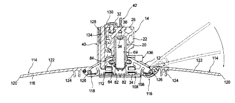
Turning now to the main feature of the present invention, as shown in Figures
10-11, the
assembly 10 includes a plurality of attachable ramp sections 114. These are
used to provide a
smooth surface over the track 12 and prevent the track 12 from forming a
tripping hazard. Each
ramp section 114 includes a substantially rectangular body 116 having a hook
section 118 at one
end thereof, and a straight edge 120 at the opposed end adapted to lie
substantially flush with the
ground when assembled. The ramp section body 116 includes a plurality of ribs
122 on its upper
surface for gripping purposes. There are reinforcing members 124 positioned
below the body
116 which are advantageous because they reduce the overall weight of the ramp
section and
maintain strength. The hook section 118 extends downwardly from the body 116,
then inwardly
and upwardly with respect to the track 12.
Between the lower end of the external walls 76 and 78, and the internal walls
68 and 74
respectively, there are defined receiving channels 125 for engaging the hook
section 118 of each
PAGE 14156* RCVD AT 2/1712010 5:16:07 PM [Eastern Standard Time)*
SVR:F00003/7* DNIS:3907 CSID:3063525250 " DURATION (mm-ss):54-52
02/17/2010 03 : 35 PM CA 02696672 2010-02-17
Page: 15
ramp section 1.14. In particular, each ramp section 114 is configured to
engage the receiving
channels 125 by way of a rotatable snap-fit. Figure 12 illustrates this
process, whereby the hook
section 118 is inserted into the receiving channel 125 and then urged upwardly
while rotating
edge 120 of the body downwardly until the hook section 118 is snap-fit in
place. This ramp pivot
5 geometry is designed to allow removal and refitting of ramps
(for re-levelling purposes) without
having to lift up or up-end the track 12.
Because the receiving channel 125 is located on the underside of the track
assembly,
engagement with the hook section 118 occurs without any obstruction or
disturbance to the
surface above, resulting in a flush upper surface that is free from gaps that
may result in items
10 catching on the track, and from tripping hazards.
A rubber tube 126 is also inserted between the rounded end of the external
walls 76 and
78 and the junction between the downwardly and inwardly extending surfaces of
the hook
section 118. The tube 126 provides a down-force and minitnises ramp 'kick-up"
which could
create a tripping hazard. A further advantage to the rubber tube 126 is that
it also acts as a
flexible joiner, assisting in handling and simultaneous fitting of multiple
ramp sections to the
track 12.
The use of such ramps allows for easy access to the service area between
shelving units
in that the tripping hazard is reduced. It also provides for a relatively flat
surface for wheelchairs
and the like to easily traverse over.
/() Finally, the runner 14 is able to be locked at different
positions along the track 12. A
locking bracket 40 is shown in the drawings which is also engageable to an
upper slot 28 of the
runner 14, as well as the side slots, by means described above. The locking
bracket 40 includes a
housing 128 mounted to the runner 14, the housing 128 defining a vertical
chamber extending
downwardly alongside the runner 14 to the track 12. The chamber includes a
vertical aperture
130. When the shelving unit is to be locked, the runner is moved along the
track 12 until the
vertical aperture 130 becomes co-axially aligned with an aperture 132 that has
been pre-drilled
into the track 12. Once aligned, a locking pin 134 can be inserted through the
co-axially aligned
apertures 130 and 132, into the hollow region 86 where it rests on the base
66, thereby locking
the runner 14 to the track 12.
A jig 136 is provided for forming the pre-drilled apertures 132 in the track
12. The jig
136 is an elongate structure mountable to the track 12 in a transverse
arrangement as shown in
PAGE 15156* RCVD AT 211712010 5:16:07 PM [Eastern Standard Time]*
SVR:F0000317* DNIS:3907 " CSID:3063525250 = DURATION (mm-ss):34-52
CA 02696672 2015-02-20
11
Figure 1. The jig 136 includes a downwardly extending section 138 at its
centre which extends
inside channel 80, as well as downwardly extending sections 140 at ends
thereof which abut with
the extema.l walls 76 and 78 of the track 12. On opposed ends of the jig 136
are apertures 144
and 146.
The jig 136 is first adapted to be mounted to the track 12 so that aperture
144 is .
-positioned over a desired point to be drilled. The purpose of this smaller
aperture 144 is to inark
the track 12 with a suitable tool (not shown), the mark acting as a locating
guide for a drill bit or
the like used to drill a hole through the track 12. The jig 136 is then
demounted from the track
12, rotated by 180 degrees, and mounted to the track 12 again so that the
larger aperture 146
extends over the marked point. A drill (not shown) can then be used to drill a
hole through the
track 12 where marked.
It is to be understood that the design of some of the components shown and
described
could change where necessary. For example, where there is a mechanical driving
means
associated with the runner, one of the track external walls 78 would extend a
greater distance
outwards from the channel 80 and include a flat upper surface (not shown) for
accommodating a
drive wheel (not shown). Such a track would therefore include a further hollow
region 86. In
such circumstances, the same packers 108 could be used but simply rotated by
90 degrees so that
instead of extending longitudinally relative to the track 12, it would extend
transversely.
In any claims that fbllow and in the summary of the invention, except where
the context
requires otherwise due to express language or necessary implication, the word
"comprising" is
used in the sense of "including", i.e. the features specified may be
associated with further
features in various embodiments of the invention.