Note: Descriptions are shown in the official language in which they were submitted.
CA 02696700 2015-08-03
1
DESCRIPTION
METHOD FOR MAKING NdFeB SYSTEM SINTERED MAGNET
AND MOLD FOR MAKING THE SAME
TECHNICAL FIELD
[0001]
The present invention relates to a method for making a NdFeB system sintered
magnet. In particular, it relates to a method for making a NdFeB system
sintered magnet
having an intended form by the following processes: filling a container (which
will
hereinafter be referred to as "mold") designed to match the shape and size of
the product
with an alloy powder for a NdFeB system sintered magnet (which will
hereinafter be
referred to as "alloy powder"); applying a magnetic field to the alloy powder
to align the
crystal orientation of the powder; and heating the whole container with the
alloy powder
filled therein to be sintered. Hereinafter, these processes will be
collectively referred to as
"press-less process."
BACKGROUND ART
[0002]
As described in Patent Document 1, conventional press-less processes consist
of the
following procedures: filling a mold with an alloy powder having an average
particle size of
2 through 5um in such a manner that the filling density becomes 2.7 through
3.5g/cm3;
placing a lid on the mold; applying a magnetic field to the powder for
orientation; sintering
the powder; and taking out the sintered compact from the mold to perform an
aging
treatment. Although the method of measuring the aforementioned average
particle size is not
explicitly stated in Patent Document 1, it was probably measured using
Fisher's method
CA 02696700 2015-08-03
2
which was commonly used at the time when the document was filed.
[0003]
Conventionally, materials used for the mold include Mo, W, Ta, Pt, and Cr,
which
are considered to be preferable examples of metals that do not react with an
alloy powder.
However, the inventor of the present invention has noticed the significant
problem that all of
these metals have one or more of the following three disadvantages: (i) they
are expensive,
(ii) they are difficult to be machined, and (iii) they will be embrittled once
heated.
[0004]
Given this factor, the inventor of the present invention has devised the use
of Fe-Ni
alloy such as stainless steel or Permalloy, which are not mentioned in Patent
Document 1, as
the material of the mold (Patent Document 2).
It had been known that, in mass-producing a NdFeB system sintered magnet, if a
compact made by pressing an alloy powder is put on a metal plate or in a
metallic container
and is sintered, the alloy powder reacts with or strongly adheres to the Fe-Ni
alloy and the
magnet after the sintering is considerably deformed. This is probably the
reason why a Fe-Ni
alloy was not mentioned as a material for the mold in Patent Document 1.The
inventor of the
present invention has solved the problem regarding the reactivity with an
alloy powder by
coating the inside of a mold, and thereby they have devised a mold using a Fe-
Ni alloy
which is inexpensive, easy to be machined, and will not be embrittled (Patent
Document 3).
[0005]
[Patent Document 1] Japanese Unexamined Patent Application Publication No.
H07-153612
[Patent Document 2] Japanese Unexamined Patent Application Publication No.
2007-180375
[Patent Document 3] Japanese Unexamined Patent Application Publication No.
CA 02696700 2015-08-03
3
2007-180373
DISCLOSURE OF THE INVENTION
PROBLEM TO BE SOLVED BY THE INVENTION
[0006]
The inventor of the present invention has noticed that, although it can
prevent the
reaction with an alloy powder as previously described, using a mold which is
made of a
Fe-Ni alloy and whose inside is appropriately coated cannot prevent the
product from
becoming slightly curved or slightly deformed after the sintering process.
Accordingly,
with such a mold, an object which is larger than the final product must be
prepared
beforehand by the press-less process, and then its curved portion must be
removed by a
machining process to obtain the final product. This brings about a problem of
the low
product yield.
[0007]
The problem to be solved by the present invention is to provide a method in
which a
NdFeB system sintered magnet can be produced without being curved or deformed
by using
a mold which is inexpensive, easy to be machined, and will not be embrittled.
The present
invention also provides such a mold.
MEANS FOR SOLVING THE PROBLEM
[0008]
The inventor of the present invention has discovered that using a carbon
material at
least in a part of the mold solves the previously described problem. This is
attributable to the
fact that the friction between a carbon material and the sintered compact is
lower than that
between the material of a conventional mold and the sintered compact and hence
less
CA 02696700 2015-08-03
4
impedes the shrinkage of the sintered compact which occurs when a sintered
compact is
produced by a sintering process. This discovery has led to the present
invention.
[0009]
That is, the present invention provides a method for making a NdFeB system
sintered
magnet which includes the processes of: filling a powder filling/sintering
container (or mold)
with a powder; orienting the powder with a magnetic field; and charging the
whole mold
into a sintering furnace to obtain a sintered compact without applying any
mechanical
pressure to the powder in the mold, wherein:
at least a part of an inner surface of the mold is made of a carbon material.
[0010]
One of the most important matters to improve the magnetic properties of a
sintered
magnet in the process of making a NdFeB system sintered magnet is to prevent
impurities as
much as possible, and carbon is the typical element which might be mixed as an
impurity.
Accordingly, it was conventionally considered unreasonable to use a carbon
material as a
material of a mold which directly contacts with the alloy powder. However, the
inventor of
the present invention has discovered through experiments that, contrary to the
common
knowledge, carbon do not react with an alloy powder to a significant degree in
the
ultralow-oxygen atmosphere, which is generally used in a sintering process for
a NdFeB
magnet. This finding has verified the effectiveness of the present invention.
[0011]
The shape and size of the internal space of the mold is designed by taking
into
account the shrinkage in the sintering process as well as the shape and size
of the final
product.
[0012]
In the method for making a NdFeB system sintered magnet according to the
present
CA 02696700 2015-08-03
invention, a part which serves as a bottom of the mold in the sintering
process may
preferably be made of the carbon material.
[0013]
In the method for making a NdFeB system sintered magnet according to the
present
5 invention, the mold may include both a part made of a carbon material and
a part made of
metal. In this case, at least a portion of the metallic part may preferably be
made of a
ferromagnetic material. In addition, the ferromagnetic material may preferably
be placed at
both ends of the mold. Further preferably, the ferromagnetic material may be
placed in such
a manner as to surround the four sides of the internal space of the mold.
[0014]
The present invention provides a mold for making a NdFeB system sintered
magnet
by the processes of: filling an inside of the mold with a powder; orienting
the powder inside
the mold with a magnetic field; charging the whole mold into a sintering
furnace, and
heating the powder in the mold without applying any mechanical pressure to the
powder to
obtain a sintered compact of the NdFeB system sintered magnet, wherein:
at least a part of an inner surface of the mold is made of a carbon material.
[0015]
The mold may include a plurality of cavities which are separated from each
other by
a plurality of divider plates.
EFFECTS OF THE INVENTION
[0016]
In the present invention, a carbon material, which has a low friction against
a sintered
compact, is used as the material of the mold. This enables the production of
NdFeB system
sintered magnets without bringing about a curve or deformation caused by a
friction due to a
CA 02696700 2015-08-03
6
sintering shrinkage. Furthermore, carbon materials have advantages in that
they are
inexpensive, easy to be machined, and will not be embrittled even after
repeated uses of the
mold. Such effects can be notably obtained by using a carbon material as the
bottom of the
mold, which is subjected to the load of the sintered compact in the sintering
process.
[0017]
The use of such mold that both a part made of a carbon material and a part
made of
metal are included and at least a portion of the metallic part is made of a
ferromagnetic
material increases the accuracy of the orientation of the magnetic field. In
particular,
providing the ferromagnetic material in such a manner as to surround the four
sides of the
internal space of the mold further increases the accuracy of the orientation
of the magnetic
field because the ferromagnetic material part forms a magnetically connected
magnetic
circuit.
BRIEF DESCRIPTION OF THE DRAWINGS
[0018]
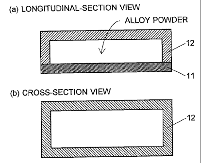
Fig. 1 is a longitudinal-section view and a cross-section view of a mold for
making a
NdFeB system sintered magnet which is an embodiment of the present invention,
in which
only the bottom plate 11 is made of a carbon material.
Fig. 2 is a longitudinal-section view and a cross-section view of a mold for
making a
NdFeB system sintered magnet in which all the walls are made of a carbon
material.
Fig. 3 is a longitudinal-section view and a cross-section view of a mold for
making a
NdFeB system sintered magnet in which magnetic poles 22 made of a
ferromagnetic
material are added at both ends of the mold of Fig. 2.
Fig. 4 is a longitudinal-section view and a cross-section view of a mold in
which a
bottom plate 31 and a lid 33 are made of a carbon material and a side plate 32
is made of a
CA 02696700 2015-08-03
7
metallic ferromagnetic material.
Fig. 5 is a longitudinal-section view and a cross-section view of a mold for
making a
NdFeB system sintered magnet including divider plates 36.
Fig. 6 is a picture showing an example of the mold according to the present
invention
and a NdFeB system sintered magnet made by using the mold by the making method
according to the present invention.
Fig. 7 is a picture showing an example of the mold made of only carbon
according to
the present invention and a NdFeB system sintered magnet made by using the
mold by the
making method according to the present invention.
Fig. 8 is a picture showing an example of the mold including magnetic poles
according to the present invention and a NdFeB system sintered magnet made by
using the
mold by the making method according to the present invention.
Fig. 9 is a picture showing an example of the mold including divider plates
according
to the present invention and a NdFeB system sintered magnet made by using the
mold by the
making method according to the present invention.
Fig. 10 is a picture showing an example of a mold of a comparative example and
a
NdFeB system sintered magnet made by using the mold.
Fig. 11 is a top view showing the positions where samples were taken from a
manufactured NdFeB system sintered magnet to measure the magnetic properties.
Fig. 12 is a table showing the magnetic properties of the NdFeB system
sintered
magnets made in the present embodiment.
EXPLANATION OF NUMERALS
[0019]
11,31 ... Bottom Plate
CA 02696700 2015-08-03
8
12 ... Side Plate/Top Plate
33, 42, 52 ... Lid
21 ... Wall
22, 54, 63 ... Magnetic Pole
32 ... Side Plate
35 ... Thin Carbon Plate
36, 62 ... Divider Plate
41 ... Stainless Container
43, 53, 55, 64, 72 ... NdFeB system sintered Magnet
51, 61 ... Container
71 ... Stainless Mold
BEST MODE FOR CARRYING OUT THE INVENTION
[0020]
An embodiment of the method for making a NdFeB system sintered magnet and the
mold for making a NdFeB system sintered magnet according to the present
invention will be
described with reference to Figs. 1 through 5.
Fig. 1 is an example of a mold for making a NdFeB system sintered magnet
according to the present invention. In this mold, only the bottom plate 11 is
made of a carbon
material, and the rest, or the side plate/top plate 12, is made of stainless
steel. With this mold,
the orientation of magnetic field can be performed either parallel or
perpendicularly to the
bottom plate 11. A coating (not shown) for preventing a reaction with an alloy
powder is
applied to the inner walls of the side plate/top plate 12. Applying a coating
to stainless steel
is detailed in Patent Document 3. The bottom plate 11 does not require the
coating. The
carbon plate may preferably has a thickness of 1 through 10 mm, in view of the
strength and
CA 02696700 2015-08-03
9
thermal conduction.
[0021]
Fig. 2 shows a mold for making a NdFeB system sintered magnet in which all the
walls 21 are made of a carbon material. Also with this mold, the orientation
of magnetic field
can be performed either parallel or perpendicularly to the bottom plate. An
adequate
mechanical strength might not be obtained only with the carbon material. In
such a case, the
outside of the walls may be covered with a metal case made of stainless steel
or other
materials. A mold made of only a carbon material as this has an advantage in
that a
preferable sintered compact can be obtained without applying any coating.
[0022]
Fig. 3 shows a mold in which magnetic poles 22 made of a ferromagnetic
material
are added at both ends of the mold of Fig. 2. In this case, the orientation of
magnetic field is
performed parallel to the bottom plate of the walls 21. This mold can increase
the degree of
orientation of the sintered compact and decrease the dispersion of the degree
of orientation,
relative to the mold of Fig. 2. This effect is most likely attributable to the
fact that the
magnetic powder oriented by a pulsed magnetic field is attracted by the
magnetic poles to be
highly oriented and that this state remains. For the purpose of preventing the
alloy powder
from being fused to the magnetic poles 22 in the sintering process, a coating
is performed or
a thin plate made of a carbon material is attached to the side of the magnetic
poles 22 that
comes in contact with the alloy powder.
[0023]
Fig. 4 shows a mold in which a bottom plate 31 and a lid 33 are made of a
carbon
material and a side plate 32 is made of a metallic ferromagnetic material. The
side plate 32
surrounds the four sides of the space inside the mold. The inner walls of the
two sides in the
longitudinal direction among the four sides of the side plate 32 are coated
(not shown) with
CA 02696700 2015-08-03
boron nitride (BN) or other materials as described in Patent Document 3. For
the remaining
two sides, a thin plate 35 made of carbon is provided to their inner wall. The
orientation of
magnetic field is performed parallel to the bottom plate 31. When a magnetic
field is applied
parallel to the bottom plate 31 with the mold filled with an alloy powder,
magnetic flux from
5 the magnetic powder (or alloy powder) in the mold generates a closed circuit
through the
side plate 32 made of a ferromagnetic material. This decreases the intensity
of the magnetic
flux that leaks from the mold after the magnetic field is oriented.
Accordingly, in the case
where a plurality of molds are present in a sintering furnace, the interaction
between the
molds is reduced, facilitating the handling of the molds. In addition, the
variation of
10 orientations caused by such an interaction is reduced.
[0024]
In the magnetic poles 22 and the side plate 32, the portions which act as the
magnetic
poles in the process of the orientation of magnetic field may preferably be a
laminate of thin
plates of ferromagnetic metal plates or a compact of powdery ferromagnetic
metal. In such a
laminate or a compact of powder, the thin plates or the grains in the powder
are isolated from
each other by a substance having a high electrical resistance. Accordingly,
the eddy current
in the magnetic poles is suppressed in the process of the orientation of
magnetic field, which
enhances the linearity of the magnetic lines of flux which pass through the
magnetic powder
and the magnetic pole. This further enhances the orientation of the magnetic
powder. As a
result, the deformation and the variation of magnetic properties of the
sintered compact after
the sintering process are suppressed, enabling the production of a high-
quality NdFeB
system sintered magnet.
[0025]
Fig. 5 shows a mold in which a plurality of divider plates 36 made of a carbon
material are attached in the space inside the mold of Fig. 4. With this mold,
one product is
CA 02696700 2015-08-03
11
produced from each space separated by the divider plates 36. Therefore, many
products can
be made at a time.
[0026]
The carbon material used in the method of the present invention is typically
made by
a powder-molding method, and includes the following kinds: carbonaceous
extruded
material; graphite extruded material; graphite pressed material; and isotropic
graphite
material. Among them, the isotropic graphite material, which has the highest
density, is best
for the method of the present invention. In the method of the present
invention, the specific
gravity, by which carbon materials can be classified, may be preferably not
less than 1.7
g/cm3 to ensure an adequate strength. As an alternative carbon material, a
carbon fiber
reinforced-carbon matrix-composite (which is called a C/C composite) is also a
preferable
material for the bottom plate 11 of Fig. 1, and for the bottom plate 31 and
the lid 33 of Figs.
4 and 5. In the process of tapping a powder to densely pack it in the mold,
C/C composite
materials are not easily damaged since they are strong even in a thin form,
while carbon
materials have a low mechanical strength and is easy to be damaged. Therefore,
a C/C
composite material is suitable as the material of the bottom plates and lids.
As the divider
plates of Fig. 5, metal plates made of stainless steel, molybdenum (Mo), or
other materials
can be used other than various carbon materials as previously described. In
the case where
metal plates are used, it is preferable to apply a coating with a BN powder or
graphite
powder and wax by the method described in Patent Document 3.
EMBODIMENTS
[0027]
Figs. 6 through 10 show embodiments of the molds of the present invention and
examples of anisotropic NdFeB system sintered magnets made by using these
molds. Each
CA 02696700 2015-08-03
12
figure is a picture including a mold and a sintered compact made therewith.
Fig. 6 is a picture of a mold composed of a nonmagnetic stainless container 41
which
was made by a sheet metal processing and a lid 42 which was a C/C composite
plate. A
coating with BN and wax was performed to the inner walls of the stainless
container 41.
Using this mold, an NdFeB system sintered magnet was produced. The magnetic
powder
used was prepared by grinding a NdFeB system sintered magnet to powders with
an average
grain size of 311m (which was measured by a laser method) by nitrogen jet
milling without
adding oxygen. The composition of the NdFeB system sintered magnet in weight
ratio was
normal: 31.5% Nd, 1% B, 1% Co, 0.2% Al, 0.1% Cu, and the rest Fe. The amount
of oxygen
in the powder was 1500 ppm. The mold was filled with this powder to a filling
density of 3.6
g/cm3 in a glove box filled with high-purity Argon (Ar) with a dew point of
not more than
-70 C. After that, the lid 42 was attached, and a magnetic field of 6T was
applied parallel to
the lid to orient the magnetic powder. Then, the mold was so reversed that the
lid 42 faced
down (i.e. it became the bottom), and it was sintered in a vacuum of 2 x10⁻⁴Pa
at 985 C. As a
result, as shown in Fig. 6, a very good-quality and high-density NdFeB system
sintered
magnet 43 was obtained which has no curve, chip, or crack. The sintered
density was 7.53
g/cm3.
[0028]
Fig. 7 shows a mold made of only a carbon material and a NdFeB system sintered
magnet made by using the mold. A container 51 of the mold was made of an
isotropic
graphite material with a specific gravity of 1.83 g/cm3 and a lid 52 was made
of a C/C
composite carbon material. The magnetic powder used, the filling density, and
the sintering
temperature were the same as in the embodiment of Fig. 6. In this manner, a
good-quality
NdFeB system sintered magnet 53 was produced without performing a coating to
the inner
walls of the mold before filling it with the powder. This is a great advantage
of the use of a
CA 02696700 2015-08-03
13
mold entirely made of carbon. It has been confirmed that the mold will have
practically no
damage after repeated uses and can repeatedly produce very good-quality
sintered compacts.
With a method using a conventional mold press, it is extremely difficult to
individually
produce NdFeB system sintered magnets which are thin, large in area, and
magnetized in the
direction parallel to the plane, as in the present example. The method of the
present invention
makes it possible to produce such a low-profile NdFeB system sintered magnet.
[0029]
Fig. 8 shows a mold which was entirely made of a carbon material as in Fig. 7
and in
which magnetic poles 54 were additionally provided at both ends of the cavity.
Fig. 8 also
shows a NdFeB system sintered magnet 55 made by using the mold. The method for
making
the NdFeB system sintered magnet was the same as previously described, and
under the
same conditions, the production was performed five times. As is seen from this
figure, with
this method, an extremely low-profile and good-quality planar NdFeB system
sintered
magnet can be obtained.
[0030]
Fig. 9 shows a mold composed of: a container 61 made of a carbon material;
divider
plates 62 made of a carbon material; and magnetic poles 63 at both ends of the
container 61.
Fig. 9 also shows a NdFeB system sintered magnet 64 made with the mold. The
powder used
and the manufacturing conditions were the same as in the examples of Figs. 6
through 8. It is
clear that this mold enables an efficient production of many planar NdFeB
system sintered
magnets. Furthermore, the use of a carbon material in the container 61 and the
divider plates
62 saves a coating to the inner walls of the mold, reducing the cost.
[0031]
As a comparative example, Fig. 10 shows an example of making a NdFeB system
sintered magnet with a mold 71 which was entirely made of stainless steel
without using a
CA 02696700 2015-08-03
14
carbon material. A BN coating was performed to all the inner walls of the
stainless mold 71.
The powder used and the manufacturing conditions were the same as in the
examples of Figs.
6 through 9. To make a NdFeB system sintered magnet by a press-less process
using a mold
entirely made of stainless steel, it is necessary to apply a flawless coating
to the inner walls
of the mold. Even the slightest flaw will cause adhesion of a sintered compact
to the flaw
portion, which makes the compact to be a defective product, and furthermore
damages the
mold. However, even if the coating to the mold is perfect, it is inevitable
that the NdFeB
system sintered magnet 72 is slightly curved by the use of the stainless mold
71 as illustrated
in Fig. 10. Such a curve is likely to occur due to the friction between the
product (or powder)
and the upper surface of the bottom plate while the powder which fills the
mold shrinks to
increase in density in the sintering process. This friction is assumed to
occur as follows: a
portion of the NdFeB alloy powder melts to form a liquid phase, and the liquid
phase
marginally penetrates through the interspaces of the BN powder to come in
contact with the
inner surface of the metallic mold. Such slight contacts cannot be avoided no
matter how
perfectly the coating is performed with a BN powder or other materials.
[0032]
On the other hand, a curve does not occur in the present invention. The reason
is
assumed to be as follows: a reaction between the liquid phase of NdFeB alloy
and carbon
occurs to a very slight degree within the range of the temperatures for
sintering a NdFeB
system sintered magnet. Accordingly, the friction between the product (or
powder) and the
upper surface of the carbon bottom plate during a sintering shrinkage is
extremely low, and
consequently the upper surface and lower surface of the product shrink
equally. Since
products without a curve can be produced, a machining process for making the
final product
is simplified, significantly improving the yield. Therefore, the price of the
product can be
reduced, which is very favorable.
CA 02696700 2015-08-03
[0033]
A NdFeB system sintered magnet was made by using molds which belonged to the
types shown in Fig. 2 (without magnetic poles) and Fig. 3 (with magnetic
poles) and was
taller than the molds shown in Figs. 6 through 9. The manufacturing conditions
were as
5 follows: filling density of 3.6 g/em3; magnetic field for orientation of 6T;
sintering
temperature of 985 C; sintering time of two hours; and the sintering process
being followed
by a quenching process from 800 C and a heat treatment at 500 C for two hours.
These
manufacturing conditions were applied to both molds. The shape and size of the
cavity of
the two molds were the same: 80mmx6Ommx6.9mm. The magnetization was performed
in
10 the direction of the side of 80mm. The sizes of the two sintered
compacts obtained were
almost the same: 57mmx51.5mmx5.9mm. From these sintered magnets, a rectangular
parallelepiped of 7mmx4mmx7mm (the magnetization was performed in the
direction of
one of the two 7mm sides) was taken from each of the three positions (A. near
a corner of
the mold, B. near the center of one wall of the mold, and C. at the center of
the cross
15 section) shown in Fig. 11 and their magnetic properties were
measured. Fig. 12 shows the
magnetic properties of these three rectangular parallelepiped samples. This
result
demonstrates that a NdFeB system sintered magnet having an excellent magnetic
properties can be obtained by the present invention, regardless of the
presence of magnetic
poles in the mold. In particular, as a NdFeB family sintered magnet including
no
dysprosium (Dy), the value of the coercive force lid was higher than those of
the
commercially available products by 3 through 4k0e. Such a high coercive force
is
attributable to the use of a press-less process, in which a contamination by
oxygen during
the process is avoided as much as possible.
[0034]
Fig. 12 also shows that the mold of Fig. 3 including magnetic poles has an
averagely
CA 02696700 2015-08-03
16
larger residual flux density Br and maximum energy product (BH)max, and a
smaller
positional variation. In addition, with regard to the degree of orientation
13,-/Jõ in the case
where the mold of Fig. 2 including no magnetic poles was used, a positional
variation was
observed in which the degree of orientation Br/.1, was smaller at the center
than at the comer
of the sample. On the other hand, in the mold of Fig. 3 having magnetic poles,
the degree of
orientation was as high as 95% level regardless of the sampling positions. In
particular, at the
position A, the degree of orientation is much higher in the mold with magnetic
poles than in
the mold without magnetic poles. This shows that the mold in which
ferromagnetic magnetic
poles are provided at both ends of the cavity can produce products having
better properties
and smaller variance of the properties than the mold made of only a carbon
material.