Note: Descriptions are shown in the official language in which they were submitted.
CA 02696769 2 013-08-2 1
WO 2009/026441 PCT/US2008/073868
NON-INTERCHANGEABLE CONNECTING VALVES
FOR FUEL CARTRIDGES
FIELD OF THE INVENTION
[0001J This invention generally relates to valves that connect fuel cartridges
to various fuel
cells and fuel refilling devices, More particularly, this invention relates to
non-
interchangeable connecting valves comprising at least one fixedly attached
center post and at
least one internal elastomeric seal, which opens when compressed by a tube
having
predetermined size and dimensions.
BACKGROUND OF THE INVENTION
[00021 Fuel cells are devices that directly convert chemical energy of
reactants, i.e., fuel and
oxidant, into direct current (DC) electricity. For an increasing number of
applications, fuel
cells are more efficient than conventional power generation, such as
combustion of fossil
fuel, as well as portable power storage, such as lithium-ion batteries.
[0003] In general, fuel cell technology includes a variety of different fuel
cells, such as alkali
fuel cells, polymer electrolyte fuel cells, phosphoric acid fuel cells, molten
carbonate fuel
cells, solid oxide fuel cells and enzyme fuel cells. Fuel cells generally run
on hydrogen (H))
fuel, and they can also consume non pure hydrogen fuel, Non pure hydrogen fuel
cells
include direct oxidation fuel cells, such as direct methanol fuel cells
(DIVIFC), which use
methanol, or solid oxide fuel cells (SOFC), which use hydrocarbon at high
temperature.
Hydrogen fuel can be stored in compressed form or within compounds such as
alcohols or
hydrocarbons or other hydrogen containing materials that can be reformed or
eonverted into
hydrogen fuel and byproducts. Hydrogen can also be stored in chemical
hydrides, such as
sodium borohydride (NaBRi), that react with water or an alcohol to produce
hydrogen and
byproducts. Hydrogen can also be adsorbed or absorbed in metal hydrides, such
as
lanthanum pentanickel (I..aNi5) at a first pressure and temperature and
released to fuel a fuel
cell at a second pressure and temperature.
[0004] Most hydrogen fuel cells have a proton exchange membrane or polymer
electrolyte
membrane (PEM), which allows the hydrogen's protons to pass through but forces
the
electrons to pass through an external circuit, which advantageously can be a
cell phone, a
- 1 -
CA 02696769 2013-08-21
WO 2009/026441 PCT/US2008/073868
personal digital assistant (PDA.), a computer, a power tool or any device that
uses electron
flow or electrical current. The fuel cell reaction can be represented as
follows:
Half-reaction at the anode of the fuel cell:
21r +
Half-reaction at the cathode of the fuel cell:
2(2Fr + 2e-) + 02 21420
[0005] Generally, the PEM is made from a polymer, such as Nafion available
from DuPont,
which is a perfluorinated sulfonic acid polymer having a thickness in the
range of about 0.05
mm to about 0.50 mm, or other suitable membranes. The anode is typically made
from a
Tefionized carbon paper support with a thin layer of catalyst, such as
platinum-ruthenium,
deposited thereon. The cathode is typically a gas diffusion electrode in which
platinum
particles are bonded to one side of the membrane.
[00061 For DMFC, the chemical-electrical reaction at each electrode and the
overall reaction
for a direct methanol fuel cell are described as follows:
Half-reaction at the anode:
CII3OH + 1-1,0 CO, + 6H+ + 6e-
Half-reaction at the cathode:
1.502 + 6H+ + 6e- 3H10
The overall fuel cell reaction:
CH3OH + 1.502 + 21120
DMFCs are discussed in U.S. Patent NOS. 4,39(1,603 and 4,828,941.
[00071 In a chemical metal hydride fuel cell, sodium borohydride is reformed
and reacts as
follows:
NaBH4 + 2H20 (heat and/or catalyst) 4(H2) (NaB0,)
Suitable catalysts for this reaction include platinum and ruthenium, and other
metals_ The
hydrogen fuel produced from reforming sodium borohydride is reacted in the
fuel cell with an
oxidant, such as 02, to create electricity (or a flow of electrons) and water
by-product,
_ _
CA 02696769 2013-08-21
WO 2009/02644.1 PC.T/US200S/07386S
illustrated above. Sodium borate (NaB02) by-product is also produced by the
reforming
process. A sodium borohydride fuel cell is discussed in U.S. Patent No.
4,261,96.
[0008] Valves are needed for transporting fuel between fuel cartridges, fuel
cells and/or fuel
refilling devices. The known art discloses various valves and flow control
devices such as
those described in U.S. patent nos. 6,506,513 and 5,723,229 and in U.S.
published application
nos. 2003/0082427 and 2002/0197522. A need, however, exists for improved
valves that
allow venting of gas, maintaining seals, improving the flow of fuel through
the valve, among
other things. To a certain extent., this need for improved connecting valves
for fuel cartridges
has been addressed by commonly owned, co-pending U.S. published application
nos.
2005/0022883, 2006/0196562 and 2010/0099009. Nonetheless, there still exists
the need
for connecting valves that cannot be readily opened. Some of the inventive
valves described
herewithin were described in commonly-Owned, co-pending U.S. provisional
application
serial no. 60/957,362 filed on August 22, 2007.
SUMMARY OF THE INVENTION
[0009] The inventive valve is usable with fuel supplies or cartridges
containing fuel for fuel
cells and comprises two valve components. The first valve component is
normally sealed and
the second valve component has a hollow tube designed to enter the first valve
component to
move or compress a scaling member in the first valve component to establish a
flow path
through both valve components. The first valve has a relatively immovable
center post that
protects the sealing member by limiting access thereto. One advantage of the
inventive valve
is that the hollow tube needs to have predetermined size and shape in order to
pass by the
center post to reach the sealing member
[00101 In some embodiments, the second valve component also has a sealing
member and
during connection, this sealing member is also moved or compressed to open the
second
valve member. The sealing member can be made from suitable elastomeric
materials, and can
have the shape of an 0-ring or a washer of various dimensions among others.
The hollow
tube is preferably cylindrical, but can have non-circular cross-sections,
Optionally, the
hollow tube has non-standard size and shape, i.e., not easily found in common
household
goods and other objects, to further limit access to the sealing member,
- 3 -
CA 02 6967 69 2013-08-21
WO 2009/026441 PCT/US2008/073868
BRIEF DESCRIPTION OF THE DRAWINGS
[0011] In the accompanying drawings, which form a part of the specification
and arc to be
read in conjunction therewith and in which like reference numerals are used to
indicate like
parts in the various views:
[0012] FIG. 1 is a front perspective view of a fuel supply in accordance with
the present
invention showing components from a fuel cell or a device, that the fuel cell
powers;
(0013] FIG. 2 is a front perspective view of the fuel supply of FIG, 1 without
the device side
components but with connecting tubes adapted to open the fuel supply's valves;
[0014] FIG. 3 is an exploded perspective view of the fuel supply of FIG, 2;
1100151 FIG. 4 is a cross-sectional and partial exploded view of the fuel
supply of FIG. 2;
(00161 FIG. 5 is an enlarged partial view of the fuel supply of FIG. 4 showing
the valve.
connecting the pressurized chamber of the fuel supply to the pressure
regulator;
[00171 FIG. 6 is an enlarged partial view of the fuel supply of FIG. 4 showing
the valve
connecting the fuel supply to the fuel cell or the device that the fuel cell
powers;
[001g] FIGS_ 7 and 8 show an alternatively embodiment of the valves of FIGS, 5
and 6;
[0019] FIGS, 9a-cc are cross-sectional views of another exemplary valve
according to the
present invention showing the opening sequence from closed in FIG. 9a to
engaged and open
in FIG. 9b-c, and FIG. 9d is an exploded perspective view of the valve;
[0020] FIGS_ 10a-10c are cross-sectional views of another exemplary valve
according to the
present invention showing the opening sequence from closed in FIG. 10a to
engaged and
closed in FIG. 1017) to open in FIG. 10c, and FIG. 10d is an exploded
perspective view of the
valve;
[0021] FIGS, .11a-11c. are cross-sectional views of another exemplary valve
according to the
present invention showing the opening sequence from closed in FIG. 11a to
engaged and
closed in FIG. lib to open in FIG. lie, and FIG. 11d is an exploded
perspective view of the
valve;
[0022] FIG. 122. is a cross-sectional view of an exemplary valve component
according to the
present invention, and FIG. 12b is an exploded perspective view of the valve
component;
- 4 -
CA 02696769 2013-08-21
W02009/026441 Peef'/US2008/073868
[0023] FIG, 13a is a cross-sectional view of another exemplary valve component
according
to the present invention, and FIG. 13b is an exploded perspective view of the
valve.
component;
[00241 FIGS. 14a-c are cross-sectional views of another exemplary valve
showing the
opening sequence of the valve and FIG. 14d is an exploded perspective view of
the valve;
and
[0025] FIG. 15a is an exploded cross-sectional view of another exemplary valve
and FIG.
15b is an exploded view of the valve.
DETAILED DESCRIPTION OF THE INVENTION
[00261 As illustrated in the accompanying drawings and discussed in detail
below, the
present invention is directed to a fuel supply, which stores fuel cell fuels,
such as methanol
and water, methanol/water mixture, methanol/water mixtures of varying
concentrations, pure
methanol, and/or methyl clathrates described in U.S. Patent Nos. 5,364,977 and
6,512,005
B2. Methanol and other alcohols are usable in many types of fuel cells,
DMFC, enzyme
fuel cells and reformat fuel cells, among others. The fuel supply may contain
other types of
fuel cell fuels, such as ethanol or alcohols; metal hydrides, such as sodium
borohydrides;
other chemicals that can be reformatted into hydrogen; or other chemicals that
may improve
the performance or efficiency of fuel cells. Fuels also include potassium
hydroxide (KOH)
electrolyte, which is usable with metal fuel cells or alkali fuel cells, and
can be stored in fuel
supplies. For metal fuel cells, fuel is in the form of fluid borne zinc
particles immersed in a
KOH electrolytic reaction solution, and the anodes within the cell cavities
are particulate
anodes formed of the zinc particles. KOH electrolytic solution is disclosed in
U.S. Pat. App.
Pub. No. US 2003/0077493, entitled "Method of Using Fuel Cell System
Configured to
Provide Power to One or More Loads," published on April 24, 2003. Fuels can
also include a
mixture of methanol, hydrogen. peroxide and sulfuric acid, which flows past a
catalyst formed
on silicon chips to create a fuel cell reaction. Moreover, fuels include a
blend or mixture of
methanol, sodium borohydride, an electrolyte, and other compounds, such as
those described
U.S.in Patent Nos. 6,554,877, 6,562,497 and 6,758,871. Furthermore, fuels
include those
compositions that are partially dissolved in a solvent and partially suspended
in a solvent,
described in U.S. Patent No, 6,773,470 and those compositions that include
both liquid fuel
and solid fuels, described in U.S. Pat. Appl. Pub. No. US 2002/W76602,
Suitable fuels are
- 5 -
CA 02696769 2013-08-21
vvo 2009/026441 PCF/IIS2008/073868
also disclosed in co-owned, co-pending U.S. Pat. Appl. No. 60/689,572,
entitled "Fuels for
Hydrogen-Generating Cartridges," filed on June 13, 2005
[0027] Fuels can also include a chemical hydride such as sodium borohydridc
(NaBI-14) and
an activator such as water, discussed above, or metal hydrides that absorb and
adsorb
hydrogen within the hydride's matrix at a certain temperature and pressure and
release
hydrogen to fuel the fuel cells at another temperature and pressure. Suitable
metal hydrides,
including but not limited to lanthanum pentanickel (LaNi5) and the metal
hydrides disclosed
in commonly-owned U.S. provisional application serial no. 60/782,632 filed no
March 15,
2006.
[0028] Fuels can further include hydrocarbon fuels, which include, but are not
limited to,
butane, kerosene, alcohol, and natural gas, as set forth in U.S. Pat. Appl.
Pub. No. US
2003/0096150, entitled "Liquid Hereto-Interface Fuel Cell Device," published
on May 22,
2003. Fuels can also include liquid oxidants that react with fuels. The
present invention is
therefore not limited to any type of fuels, activators, electrolytic
solutions, oxidant solutions
or liquids or solids contained in the supply or otherwise used by the fuel
cell system. The
term "fuel" as used herein includes all fuels that can be reacted in fuel
cells or in the fuel
supply, and includes, but is not limited to, all of the above suitable fuels,
electrolytic
solutions, oxidant solutions, gaseous, liquids, solids, and/or chemicals
including additives and
catalysis and Tfl i xtur es thereof.
[0029] As used herein, the term "fuel supply" includes, but is not limited to,
disposable
cartridges, refillable/reusable cartridges, containers, cartridges that reside
inside the electronic.
device, removable cartridges, cartridges that are outside of the electronic
device., fuel tanks,
fuel refilling tanks, other containers that store fuel and the tubings
connected to the fuel tanks
and containers. While a cartridge is described below in conjunction with the
exemplary
embodiments of the present invention, it is noted that these embodiments are
also applicable
to other fuel supplies and the present invention is not limited to any
particular type of fuel
supply.
[0030] The fuel supply of the present invention can also be used to store
fuels that are not
used in fuel cells, These applications can include, but are not limited to,
storing
hydrocarbons and hydrogen fuels for micro gas-turbine engines built on silicon
chips,
discussed in "Ilere Come the Microengines," published in The Industrial
Physicist (Dec.
2001/Jay. 2002) at pp. 20-25. As used in the present application, the term
"fuel cell" can also
- 6 -
CA 02696769 2013-08-21
WO 2009/026441 p(17OS2008/0738(.8
include microengi nes. Other applications can include storing traditional
fuels for internal
combustion engines and hydrocarbons, such as butane for pocket and utility
lighters and
liquid propane.
[0031] Referring to FIGS. 1-4, fuel supply '10 is shown, Fuel supply 10 can
have any
convenient shape, including but not limited to the shape shown. Fuel supply 10
has outer
casing 12, lid 14, first valve 16 and second valve 18, Lid 14 is fitted to
outer casing 12, and
is sealed thereto by 0-ring 13. Sealing can also be accomplished by adhesives
or ultrasonic
welding. First valve 16 is sized and dimensioned to mate with a pressure
regulator 211 and
second valve 18 is sized and dimensioned to mate with device valve 22. In one
embodiment,
fuel supply 10 is disposable and more preferably recyclable. More
particularly, outer casing
12 is recyclable or reusable, and inner liner 28 and/or lid 14 are disposable.
Pressure
regulator 20 and device valve 22 are preferably reusable, and are connected to
or arc parts of
the fuel cell or the device that the fuel cell powers to save costs.
[0032] Referring to FIGS. 3-5, where the internal components are shown in
detail, fuel
supply 10 has compressed gas chamber 24 and liquid fuel chamber 26, where
liquid fuel is
kept inside liner 28. As discussed above, liquid fuel can be a fuel that is
used directly by a
fuel cell, such as methanol and ethanol. Liquid fuel can also be a liquid
reactant that
hydrolyzes in a reaction chamber to produce hydrogen that powers the fuel
cell, such as water
or other activators to react with solid metal hydride to form hydrogen fuel.
[0033] First valve 1.6 allows compressed gas to exit pressurized or compressed
gas chamber
24 of fuel supply 10 to enter pressure regulator 20, and then communicate the
reduced
pressure gas back into fuel supply 10 and to liquid fuel chamber 26 to apply
pressure on liner
28. First valve 16 comprises valve body 30, which is fitted to the side walls
of compressed
gas chamber 24 and is sealed thereto with 0-ring 32. Inner center post 34 is
fixedly attached
valve body 30, e.g., interference fit, so that there is substantially no
relative movement
between inner center post 34 and valve body 30. A flow channel 36 is defined
between the
stem of inner center post .34 and valve body 30. In one example, the stern has
a cylindrical
shape and a portion of stem is filed down to form a flat surface. Inner flow
channel 36 is
formed between the flat surface and valve body 30, as best shown in FIGS. 3
and 5. Inner
elastomeric seal 38 is disposed between the head of inner center post 34 and
the top of valve
body 30, as shown, to provide a seal for inner flow channel 36. First valve 16
also has outer
center post 40, which is disposed annularly around inner center post 34,
leaving a space.
- 7 -
CA 02696769 2013-08-21
WO 2(109/02644J PCT/US2008/073868
therebctween as shown. Outer center post 40 is also fixedly attached to valve
body 30, e.g.,
interference fit, so that there is substantially no relative movement between
outer center post
40 and valve body 30. Outer flow channel 42 is defined around the outside0: +
outer center
post 40 to allow the reduced pressure gas from pressure regulator 20 to re-
enter fuel supply
10. Within fuel supply 10 outer flow channel 42 is re-directed to liquid fuel
chamber 26, as
best shown in FIG. 5. Outer elastomeric seal 44 provides a seal for outer flow
channel 42 and
is positioned below the head of outer center post 40 and optional cap 46. Cap
46 can be
omitted and valve body 30 can be extended upward to meet outer elastomeric
seal 44, or
elastomeric seal 44 can be extended downward to meet valve body 30.
[140341 While inner flow channel 36 is shown to be inside of outer flow
channel 42, these two
flow channels can be arranged in the reverse order, or side-by-side. Flow
paths 36 and 42
can also be in opposite directions, as indicated by the discussion above and
FIG. 5.
[00351 As shown in FIGS. 3 and 5, first valve 16 is closed or sealed. To open
first valve 16,
tube 48 is pushed into first valve 16. Tube 48 comprises inner tube 50 and
outer tube 52.
These tubes can be connected to each other to maintain their relative
positions, for example
by spokes or webs (not shown). Inner tube 50 is sized and dimensioned to fit
in space 54
between inner center post 34 and outer center post 40, and outer tube 52 is
sized and
dimensioned to fit in space 56 between outer center post 40 and lid 14. Inner
tube 5(1
compresses inner elastomeric seal 38 to open flow path 36 and outer tube 52
compresses
outer elastomeric seal 44 to open flow path 42. Compressed gas exits fuel
supply 10 through
flow path 36 and reduced pressure gas re-enters fuel supply through flow path
42 to
pressurize liquid fuel.
[9036] In an innovative aspect of the present invention, because first valve
16 comprises
center posts 34, 40, it is not interchangeable. In particular, valve 16 opens
only after a tube
48 with the correct diameter is inserted in the annular space around center
posts 34, 40 to
compress elastomcric seals 38, 44. Center posts 34, 40 are designed to prevent
larger or
smaller diameter foreign objects (e.g., pens, pencils, paper clips, fingers,
and the. like) from
opening the valve. Center posts 34 and 40 may be attached to valve body 30 by
various
methods, such as snap fitting, adhesive, ultrasonic welding, etc., so long as
relative motions
between the posts and the valve body are limited, Preferably, center posts 34,
40 can he
assembled after or during the filling operation. Consequently, the flow of
fuel into the
cartridge will be faster and less restricted than in other designs.
- 8 -
CA 02696769 2013-08-21
WO 2009/026441 PCT/US2008/073868
[0037] Second valve 18 is similar to first valve 16, except that it is only
configured to allow
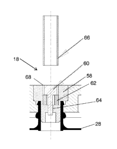
liquid fuel to exit fuel supply 10. Second valve 18 comprises valve body 58
and center post
60, which is substantially similar to inner center post 34 of first valve 18,
described above..
Elastomerie seal 62 seals second valve 18 and flow channel 64 is defined
between inner post
60 and valve body 58. Liner 28 is sealingly connected to valve body 58. Tube
66 is sized
and dimensioned to enter space 68 in second valve 18 to compress elastomeric
seal 62 to
open second valve 18 to let the liquid fuel urged by pressurized gas from flow
channel 64 to
leave fuel supply 10.
[(1038] Optionally, tubes 48 or 66 have non-standard sizes. In other words,
their dimensions
arc different than the dimensions of items commonly found in the homes or
offices, so that it
is more difficult to unintentionally compress sealing members 38, 44 or 62.
Alternatively,
tubes 48 or 66 should have non circular or polygonal (regular or irregular)
cross-sections. Of
course, center posts 34, 40 or 60 should have matching shapes in order to
receive the tubes,
[0039] In an alternative embodiment shown in FIGS. 7-8, elastomeric seals 38,
44 and 62 arc
replaced by 0-rings 38', 44' and 62' or other sealing members such as washers,
overmolded
clastomeric portions, elastomeric balls, and the like. Center posts 34' and
40' are modified to
provide angular seating surfaces to seal with the 0-rings Center post 60' in
this embodiment
has outer ring 61' to provide spacing 68' for tube 66 to enter to open second
valve 18.
[0040] As illustrated in FIGS. 5-8 as well as the other drawings, the top
surface of valves 16
and 18 facing tubes 48 and 66 can also be termed the mating surface.
[0041] In other alternative embodiments, first valve 16 or second valve 18 can
have a sealing
member 70 (e.g., an 0-ring, a sealing face, a washer, an ovemiolded
elastomeric portion, an
elastomeric ball or the like) located near the entrance of either valve. For
example, as shown
in FIGS. 9(a)-9(c) and FIGS. 10(a)-10(e), sealing member 70 can he an 0-ring
residing in
grooves defined within a valve body 58 of second valve 18. The seal is
provided between
valve body 58, sealing member 70 and center post 60. Space 68 is provided
between valve
body 58 and center post 60. In this embodiment, tube 66 is sized and
dimensioned to be
larger than center post 60, and when tube 66 is inserted into space 68 it
pushes 0-ring 70
outward to allow a flow channel 64 between tube 66 and center post 60, as
shown in FIGS.
9(b) and 9(c). Further insertion of tube 66, shown in FIG. 9(c), ensures
stability of tube 66
inside valve body 58. When tube 66 is first inserted into space 68 as shown in
FIG. 9(b), an
- 9 -
CA 02696769 2013-08-21
WO 2009/026441 PCT/US2008/073865
inter-component seal is optionally formed between tube 66 and valve body 58.
FIG. 9(d)
shows an exploded view of valve 18 and tube 66.
100421 The embodiment a FIGS. 10(a)-(d) is similar to the embodiment of FIGS.
9(a)-(d),
except that in addition to the seal provided by 0-ring 70, a second seal is
provided by
elastomeric seal 62 and center post 70. Here, when tube 66 pushes 0-ring 70
aside, valve .18
remains sealed, as shown in FIG. 10(b), until tube 66 compresses elastorneric
seal 62, as
shown in FIG. 10(c) to establish flow path 64. FIG. 10(d) shows an exploded
view of mating
tube 66 and valve 18.
[0043] Although the sequence in FIGS. 9(a)-9(c) and FIGS. 10(a)-10(e) is shown
for valve
18, a comparable sequence could be applied to form an inter-component seal
between tube 48
and valve 16 and thereafter open internal seals within valve 16.
[0044] The closing sequence. of either valve 16 or valve 18 is similar to the
reverse process of
the above-described opening sequence. Cartridge. 10 is first disengaged from a
device, either
manually or automatically using any ejection mechanism known in the art, and
any
compressed seal (e.g., elastomeric seals 38, 44 and 62, 0-rings 38, 44' and
62', or sealing
member 70) releases its stored energy and returns to its original position.
Advantageously, in
one particular embodiment, the compressed seal itself can act as the ejection
mechanism. As
a consequence, no external spring force is necessary to eject cartridge 10 and
one conserves
space within cartridge 10. After the cartridge is ejected and the elastomeric
seals return to
their original position, a center post once again engages with the elastomeric
seals to close off
flow paths to the fuel cartridge.
[00451 FIGS. 11(a)-(d) illustrate another embodiment of the present invention.
As shown, a
connecting valve 72 comprising two valve components 74 and 76. One valve
component is
mated to either a fuel supply or a device (e.g., a fuel cell, refilling
device, or any other device
suitable for use in a fuel cell system), and another valve component is mated
to the other of
the fuel supply or device. Preferably, a first valve component 74 is mated to
a device, and a
second valve component 76 is preferably mated to a fuel supply. FIGS. 11(a)-
11(c) show a
sequence depicting the connection of first valve component 74 and second valve
component
76 and the opening of internal seals therein, and FIG. 11(d) shows an exploded
view or
connecting valve 72.
-10 -
CA 02696769 2013-08-21
WO 2009/026441 PCT/US2008/073868
[0046] First valve component 74 comprises a housing with a top portion 77a and
a bottom
portion 77b. The top portion 77a encases a hose tube 78 that connects fluidly
with an 0-ring
80. The 0-ring 80 forms an internal seal with center post 81, which is shown
as being
integrally made with top housing 77a. Inner tube 82, which has a pair of
diametrically
opposite apertures 84, is provided to selectively compress 0-ring 80. The
inner tube 82 is
sized and dimensioned to fit within an outer tube 86. Tubes 82 and 86 are
sized and
dimensioned to define a space therebetween to be a part of a flow path. Both
inner tube 82
and outer tube 86 are located within bottom portion 76b, and may be connected
to each other
by spokes or webs (not shown) to maintain their relative positions. When 0-
ring 80 is not
compressed, it abuts with center post 81 to seal valve component 74. When it
is compressed,
a flow path through valve component 74 is established from hose tube 78
through
compressed 0-ring 80 into the hollow end of tube 82 and through aperture(s) 84
and though
the. space between inner tube 82 and outer tube 86.
[0047] The second valve component. 76 also comprises several elements
including a housing
88 with a top portion 88a and bottom portion 881). Advantageously, a center
post 90 is
fixedly attached to bottom portion 88b and has angular seating surfaces that
form an internal
seal with an 0-ring 92. The bottom portion 881) also has a hose tube 94 that
connects fluidly
to 0-ring 92. Outer tube 86 of valve component 74 is also larger than center
post 90 to allow
fluid to flow therebetween,
[00481 Both the first valve component 74 and the second valve component. 76
can be
connected together by bolts 96 in channels 98. Furthermore, an 0-ring (not
shown) can he
provided between first valve component 74 and second valve component 76 in
order to
facilitate an inter-component seal between the two valve components.
[00491 FIG. 11(a) shows first. valve component 74 as being unconnected to
second valve
component 76. To connect the fuel supply to the fuel cell and to transport
fuel from the fuel
supply to the fuel cell, outer tube 86 from .first valve component 74 is
inserted into the space
100 around center post 90 in second valve component 76, as shown in FIG.11
(b.), until it
reaches 0-ring 92. In FIG. 11(c), the internal seals in first valve component
74 and second
valve component 76 are opened to establish flow path 101. The internal seal in
the first valve
component 74 opens when center post 90 pushes against inner tube 82, which in
turn
compresses 0-ring SO. The internal seal in the second valve component 76 opens
when outer
tube 86 of first valve component 74 compresses 0-ring 92. A flow path is
established in
- 11 -
CA 02696769 2013-08-21
Wi) 2009/026441 PCT/US2008/073868
second valve component 76 from hose tube 94 around compressed 0-ring 92 and
through the
space between center post 90 and outer tube 86 of first valve component 74. As
shown in
FIG. 11(c), flow path 101 is a combination of the flow paths in first valve
component 74 and
in second valve component 76. Fuel may flow through flow path 101 in either
direction from
hose tube 78 to hose tube 94, and in reverse.
[0050] When establishing flow path 101, first valve component 74 can be opened
simultaneously with second valve component 76, or the two valve components may
be timed
to open in a sequential manner after a connection is made between them. As
will be
recognized by those skilled in the art, in some situations advantage may be
found in opening
the flow path to the device prior to opening the flow path to cartridge 10,
for example to
ensure that the device is prepared to receive fluid or gas prior to accessing
the fuel stored in
cartridge 10. This sequential opening may be attained by simply adjusting the
length of inner
tube 82, outer tube 86, or center post 90. For example, if first valve
component 74 is on the
device, outer tube 86 may be shortened, or inner tube 82 or center post 90 may
be lengthened.
In such a case, center post 90 moves inner tube 82 prior to outer tube 86
engaging with 0-
ring 92. Alternatively, if second valve component 76 is on the device, outer
tube 86 can be
lengthened so that it compresses 0-ring 92 prior to inner tube 82 engaging
with center post
90. Any of these structures or combinations thereof may also result in one
valve component
having a longer stroke to open its flow path than the other valve component so
that one valve
component has a longer opening sequence than the other valve component.
[0051] Another version of first valve component 74' is shown in FIGS. 12(a)
and 12(b).
Here, the center post 81 is attached to housing 77a via an interference fit,
and lower housing
portion 77b is combined with outer tube 86. Inner tube 82 is allowed to move
slightly up and
down relative to lower housing 77h/outer tube 86 to compress and uncompress 0-
ring SO.
The operation of this valve component 74' is similar to first valve component
74 described in
FIGS. 1 (a)-(d).
[0052] Another version of first valve component 74" is shown in FIGS, 13(a)-
(h). Here,
center post Si is extended downward or outward and is fixed to first housing
portion 77a by
interference fit. A single tube 82/86 replaces inner tube 82 and outer tube 86
and is movable
to compress 0-ring SO, which provides a seal with center post 80 as described
above. Tube
82/86 fits outside of center post 81and provides a gap therebetween. Retainer
ring 105 is
designed to keep tube 82/86 within valve component 74" by interfering with
outer ring 103 of
- 12 -
CA 02696769 2013-08-21
WO 2009/026441 PCT/US2008/073868
tube 82/86. When 0-ring 80 is compressed, a flow path is established from tube
78 around
the small stem of center post 81 and around compressed 0-ring 80 and into the
space between
tube 82/86 and center post 81. When connecting to second valve component 76,
shown in
FIGS. 11(a)-(d), tube 82/86 compresses 0-ring 92 of second valve component 76,
as well as
0-ring 80 of first valve component 74, either simultaneously or in sequence as
discussed
above.
[0053] Referring to FIGS. 14(a)-(d), another version of valve 18 is shown. In
this
embodiment, center post 60 is made integral to valve body 58, but can be made.
separately
and affixed to valve body 58 as discussed above and below in connection with
FIGS, 15(a)-
(4 Sealing member 62 in this case is a non-flat washer Or a lip washer
providing a lip seal
with center post 60. As best shown in FIG. 14(a), tip washer 62 is retained
between valve
body 58 and retainer 107. The scaling portion of washer 62 is oriented inward
and presses
against center post 60, as shown, to provide the seal. In this embodiment,
space 68 is
provided between retainer 107 and center post 60, and is sized and dimensioned
to receive
tube 66. Also, a clearance is provided between tube 66 and center post 60 to
allow fuel to
flow therethrough. As shown in FIG. 14(b), tube 66 is inserted into valve
component 18
through space 68 until it reaches lip washer 62 and beyond as shown in FIG.
1404 Once
tube 66 is pushed past lip washer 62, fuel flow path 64 is established as
shown.
[0054] FIGS. 15(a)0) show a variation of the valve component of FIGS. 14(a)-
(d). These
two valve components are similar to each other except that washer 62 is a flat
washer and
center post 60 is made separate from valve body 58. Furthermore, valve body 58
has cut-out
channel 109 formed therein to be a part of flow path 64.
[0055] Variations to fuel supply 10 are described in commonly-owned, co-
pending U.S.
provisional application serial no. 60/957,362 filed on August 22, 2007.
[0056] While it is apparent that the illustrative embodiments of the invention
disclosed herein
fulfill the objectives of the present invention, it is appreciated that
numerous modifications
and other embodiments may be devised by those skilled in the art.
Additionally, feature(s)
and/or element(s) from any embodiment may be used singly or in combination
with
feature(s) and/or element(s) from other embodiment(s).
- 13-