Note: Descriptions are shown in the official language in which they were submitted.
CA 02696955 2011-12-14
=
TWO DIMENSIONAL BAR CODE HAVING INCREASED ACCURACY
10 BACKGROUND OF THE INVENTION
I. Field of the Invention
The present invention relates to two-dimensional bar codes. More
specifically, the invention relates to a matrix code that provides increased
accuracy.
2. Related Art
The "two dimensional bar code" was developed by NASA to identify and track
space shuttle parts. The bar code pattern can be used to encode inventory data
or a
history of the object to which it is attached, as described in "A White Paper
on Two
Dimensional Symbols," by Paul Mathans et al. (CSPI Vision Systems 1996).
The "two-dimensional bar code" is more formally referred to as a matrix code,
a
term that applies to two-dimensional codes that code data based on the
position of dark
modules within a matrix. All of the dark modules are the same dimension, and
it is the
positions of the modules that code the data. Data Matrix is a type of two-
dimensional
- 1 -
CA 02696955 2010-02-17
WO 2008/021458 PCT/US2007/018185
matrix code containing dark and light square data modules. It is designed to
pack a lot of
information in a very small space; a Data Matrix symbol can store between one
and 3116
numeric or 2335 alphanumeric characters. A Data Matrix symbol has a finder
pattern of
two solid bars and two alternating dark and light square data modules on the
perimeter of
the symbol. These patterns are used to indicate both orientation and printing
density of
the symbol. A two-dimensional imaging device such as a CCD camera is used to
scan the
symbology.
The information in a Data Matrix symbol is encoded by absolute dot position
rather than relative dot position. While a Data Matrix symbol is easily
scalable between a
1-mil square to a 14-inch square, the actual limits are dependent on the
fidelity of the
marking device and the optics of the sensor. Data Matrix symbols can be used
for small
item marking applications using a wide variety of printing and marking
technologies.
Additional information regarding Data Matrix code is disclosed in U.S. Patents
Nos. 4,939,354; 5,053,609; 5,124,536.
It is to the solution of these and other problems that the present invention
is
directed.
SUMMARY OF THE INVENTION
It is accordingly a primary object of the present invention to provide a
matrix code
that has improved accuracy relative to a conventional Data Matrix code.
This and other objects of the invention are achieved by the provision of a
matrix
code symbol based on a conventional Data Matrix code, and comprising a two-
dimensional matrix code containing dark and light square data modules, and a
finder
- 2 -
CA 02696955 2011-12-14
pattern of two solid bars and two bars of alternating dark and light square
data modules
on the perimeter of the symbol for indicating both orientation and printing
density of the
symbol, wherein all of the dark and light modules are the same dimension, and
data is
encoded based on the absolute position of the dark modules within the matrix.
In a first embodiment, the matrix code symbol differs from a conventional Data
Matrix code in the addition of inner and outer solid bars along the base and
right-hand
side of the matrix code symbol, the inner and outer solid bars each having a
width equal
to the square data modules, the inner solid bar being light and the outer
solid bar being
dark.
In a second embodiment, the matrix code symbol differs from a conventional
Data
Matrix code in the addition of an inner solid bar and at least one outer
encoding bar along
the base and right-hand side of the matrix code symbol, the inner solid bar
and the at least
one outer encoding bar each having a width equal to the square data modules,
the inner
solid bar being light and the at least one outer encoding bar comprising a
number of side-
by-side data cells, wherein each data cell represents a single bit of binary
data and the
binary data is encoded using an error-correcting code (ECC) algorithm.
Both embodiments of the matrix code symbol can incorporate the target of a
strain
gage as described in U.S. Patent No. 6,874,370 and U.S. Patent No. 6,934,013.
A
strain gage in accordance with the present invention comprises a target
associated with a
body for which at least one of strain and fatigue damage is to be measured,
sensor means
for pre-processing a detectable physical quantity emitted by the target and
output data
representing the physical quantity, the sensor means being compatible with the
detectable
physical quantity, means for analyzing the data output by the sensor means to
define the
- 3 -
CA 02696955 2012-09-04
symbolic strain rosette, and means for measuring the strain on the body
directly based on
the pre-processed and analyzed data, wherein the target is a Symbolic Strain
Rosette
incorporated in one of the embodiments of the matrix code symbol.
In a method of measuring at least one of strain and fatigue damage on an
object
directly, in accordance with a present invention, a symbolic strain rosette
incorporated in
one of the embodiments of the matrix code symbol is associated with an object
in such a
way that deformation of the symbolic strain rosette and deformation under load
of the object
bear a one-to-one relationship. The changes in the symbolic strain rosette are
identified as a
function of time and change in the load applied to the object. The changes in
the symbolic
strain rosette are then translated into a direct measurement of strain.
In another embodiment, there is provided a target for association with an
object for
which at least one of strain and fatigue damage is to be measured, the target
incorporating a
matrix code symbol, the matrix code symbol emitting a detectable physical
quantity and
including: a Data Matrix symbol having: a two-dimensional matrix having a
perimeter and
containing dark and light square data modules, wherein data is encoded based
on the
absolute position of the dark modules within the matrix; and a finder pattern
of two solid
bars and two bars of alternating dark and light square data modules on the
perimeter of the
matrix for indicating both orientation and printing density of the symbol,
wherein all of the
dark and light data modules of the matrix are the same dimension, wherein the
two solid
bars are on one pair of adjacent sides of the perimeter of the matrix and the
two bars of
alternating dark and light data modules are on the opposite pair of adjacent
sides of the
perimeter of the matrix, and wherein the finder pattern defines the perimeter
of the Data
Matrix symbol; a solid inner bar outside the perimeter of the Data Matrix
symbol, only
adjacent each of the finder pattern bars of alternating dark and light data
modules; and at
- 4 -
CA 02696955 2012-09-04
least one outer bar positioned adjacent each inner bar, with each inner bar
being interposed
between the perimeter of the Data Matrix symbol and the at least one outer
bar, wherein the
at least one outer bar is configured to increase the accuracy of the use of
the Data Matrix
symbol; wherein the inner and outer bars each have a width equal to the square
data
modules.
In another embodiment, there is provided a non-linear strain gage comprising:
a
target associated with an object for which at least one of strain and fatigue
damage is to be
measured, the target comprising a matrix code symbol emitting a detectable
physical
quantity and including: (a) a Data Matrix symbol having: a two-dimensional
matrix having
a perimeter and containing dark and light square data modules, wherein data is
encoded
based on the absolute position of the dark modules within the matrix; and a
finder pattern of
two solid bars and two bars of alternating dark and light square data modules
on the
perimeter of the matrix for indicating both orientation and printing density
of the symbol,
wherein all of the dark and light data modules of the matrix are the same
dimension,
wherein the two solid bars are on one pair of adjacent sides of the perimeter
of the matrix
and the two bars of alternating dark and light data modules are on the
opposite pair of
adjacent sides of the perimeter of the matrix, and wherein the finder pattern
defines the
perimeter of the Data Matrix symbol; (b) a solid inner bar outside the
perimeter of the Data
Matrix symbol, only adjacent each of the finder pattern bars of alternating
dark and light
data modules; and (c) at least one outer bar positioned adjacent each inner
bar, with each
inner bar being interposed between the perimeter of the Data Matrix symbol and
the at least
one outer bar, wherein the at least one outer bar is configured to increase
the accuracy of the
use of the Data Matrix symbol; wherein the inner and outer bars each have a
width equal to
the square data modules; sensor means for pre-processing the detectable
physical quantity
- 4a -
CA 02696955 2012-09-04
emitted by the target and output data representing the physical quantity, the
sensor means
being compatible with the detectable physical quantity; means for analyzing
the data output
by the sensor means to define the matrix code symbol; and means for measuring
the strain
on the object directly based on the pre-processed and analyzed data.
In another embodiment, there is provided a method of measuring strain on an
object
directly, comprising the steps of: associating a target with an object in such
a way that
deformation of the matrix code symbol and deformation under load of the object
bear a one-
to-one relationship, wherein the target comprises a matrix code symbol
emitting a detectable
physical quantity and including: (a) a Data Matrix symbol having: a two-
dimensional matrix
having a perimeter and containing dark and light square data modules, wherein
data is
encoded based on the absolute position of the dark modules within the matrix;
and a finder
pattern of two solid bars and two bars of alternating dark and light square
data modules on
the perimeter of the matrix for indicating both orientation and printing
density of the
symbol, wherein all of the dark and light data modules of the matrix are the
same
dimension, wherein the two solid bars are on one pair of adjacent sides of the
perimeter of
the matrix and the two bars of alternating dark and light data modules are on
the opposite
pair of adjacent sides of the perimeter of the matrix, and wherein the finder
pattern defines
the perimeter of the Data Matrix symbol; (b) a solid inner bar outside the
perimeter of the
Data Matrix symbol, only adjacent each of the finder pattern bars of
alternating dark and
light data modules; and (c) at least one outer bar positioned adjacent each
inner bar, with
each inner bar being interposed between the perimeter of the Data Matrix
symbol and the at
least one outer bar, wherein the at least one outer bar is configured to
increase the accuracy
of the use of the Data Matrix symbol; wherein the inner and outer bars each
have a width
equal to the square data modules; identifying the changes in the matrix code
symbol as a
- 4b -
CA 02696955 2012-09-04
function of time and change in the load applied to the object; and translating
the changes in
the matrix code symbol into a direct measurement of strain.
Other objects, features and advantages of the present invention will be
apparent to
those skilled in the art upon a reading of this specification including the
accompanying
drawings.
BRIEF DESCRIPTION OF THE DRAWINGS
The invention is better understood by reading the following Detailed
Description of
the Preferred Embodiments with reference to the accompanying drawing figures,
in which
like reference numerals refer to like elements throughout, and in which:
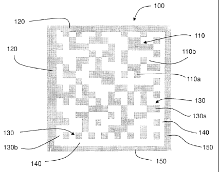
FIGURE 1 shows a first embodiment of a matrix code symbol in accordance with
the present invention.
FIGURE 2 shows a second embodiment of a matrix code symbol in accordance with
the present invention.
- 4c -
CA 02696955 2010-02-17
WO 2008/021458 PCT/US2007/018185
DETAILED DESCRIPTION OF THE PREFERRED EMBODIMENTS
In describing preferred embodiments of the present invention illustrated in
the
drawings, specific terminology is employed for the sake of clarity. However,
the
invention is not intended to be limited to the specific terminology so
selected, and it is to
be understood that each specific element includes all technical equivalents
that operate in
a similar manner to accomplish a similar purpose.
FIGURES 1 and 2 respectively show first and second embodiments 100 and 200
of a matrix code symbol in accordance with the present invention. Both
embodiments of
the matrix code symbol are based on the Data Matrix code disclosed in U.S.
Patents Nos.
4,939,354; 5,053,609; and 5,124,536, and can incorporate a Symbolic Strain
Rosette for
use as a target in a compressed symbology strain gage as described in U.S.
Patent No.
6,934,013.
The first embodiment of the matrix code symbol 100 (shown in FIGURE 1)
comprises a two-dimensional matrix code 110 containing dark and light square
data
modules 110a and 110b arranged in a matrix, and a finder pattern of two solid
bars 120
and two bars 130 of alternating dark and light square data modules 130a and
130b on the
perimeter of the matrix for indicating both orientation and printing density
of the symbol
100, wherein all of the dark and light modules 110a, 110b, 130a, and 130b are
the same
dimension, and data is encoded based on the absolute position of the dark
modules 110a
within the matrix. As shown in FIGURE 1, the two solid bars 120 are on one
pair of
adjacent sides of the perimeter, and the two bars 130 of alternating dark and
light data
modules 130a and 130b are on the opposite pair of adjacent sides. There are no
restrictions placed on the colors of the dark and light modules, except that
sufficient
- 5 -
CA 02696955 2012-09-04
contrast is provided to enable a sensor to determine module state (that is,
"dark" or
"light").
The first embodiment 100 of the matrix code symbol differs from a conventional
Data Matrix code in the addition of inner and outer solid bars 140 and 150
along the base
and right-hand side of the matrix code symbol, that is, adjacent to the two
bars 130 of
alternating dark and light square data modules 130a and 130b, as shown in
FIGURE 1.
The inner and outer solid bars 140 and 150 each have a width equal to the
square data
modules 110a and 110b, the inner solid bar 140 being light and the outer solid
bar 150
being dark. The dark, outer solid bar 150 increases the accuracy of the use of
the Data
Matrix symbol but does not provide more encoded data.
The first embodiment 100 of the matrix code symbol can incorporate the target
of
a strain gage as described in U.S. Patents Nos. 6,874,370 and 6,934,013. A
strain
gage employing the first embodiment uses a computer to implement the same
theory
and programs as the strain gage of U.S. Patent No. 6,934,013. When used as
such a target,
the first embodiment increases the accuracy of the strain measurements made.
The second embodiment 200 of the matrix code symbol (FIGURE 2) comprises a
two-dimensional matrix 110 containing dark and light square data modules 110a
and
110b, and a finder pattern of two solid bars 120 and two bars 130 of
alternating dark and
light square data modules 130a and 130b on the perimeter of the symbol 200 for
indicating both orientation and printing density of the symbol, wherein all of
the data
modules 110a, 110b, I30a, and 130b are the same dimension and data is encoded
based
on the absolute position of the dark modules 110a within the matrix. The
second
- 6 -
CA 02696955 2012-09-04
embodiment 200 of the matrix code symbol differs from a conventional Data
Matrix code
in the addition of an inner solid bar 140 and at least one outer encoding bar
250 along the
base and right-hand side of the matrix code symbol 200, that is, adjacent to
the two bars
130 of alternating dark and light square data modules 130a and 130b, as shown
in
FIGURE 2. The inner solid bar 140 and the at least one outer encoding bar 250
each have
a width equal to the square data modules 110a, 110b, 130a, and 130b, the inner
solid bar
being 140 light and the at least one outer encoding bar 250 being the same as
a data
region as described in U.S. Published Application No. 2006-0289652 Al (Serial
No.
11/167,558, filed March 24, 2006) comprising a number of side-by-side data
cells 250a,
wherein each data cell 250 represents a single bit of binary data and the
binary data is
encoded using an error-correcting code (ECC) algorithm. The at least one outer
encoding
bar 250 is bounded by solid dark lines 250b, which provide an outer boundary
for the
ECC algorithm and greater accuracy for strain measurement.
Although the second embodiment 200 as shown in FIGURE 2 has one encoding
bar 250 along the base and right-hand side of the matrix code symbol, the
matrix code
symbol 200 in aceordance with the second embodiment of the invention can have
a
plurality of encoding bars 250 along the base and right-hand side. The
encoding bars 250
permit the encoding of additional data and provide improved accuracy relative
to a
conventional Data Matrix symbol.
The second embodiment 200 of the matrix code symbol can incorporate the target
of a strain gage as described in U.S. Patents Nos. 6,874,370 and 6,934,013. A
strain gage
employing the second embodiment also uses a computer to implement the same
theory,
algorithms, and computer programs as the strain gage of U.S. Patent No.
6,934,013, which
(1) identify the Symbolic
- 7 -
CA 02696955 2010-02-17
WO 2008/021458
PCT/US2007/018185
Strain Rosette and the changes therein as a function of time and change in the
load, (2)
translate the changes in the Symbolic Strain Rosette into strain, and (3)
display it in a
suitable format. When used as such a target, the second embodiment also
increases the
accuracy of the strain measurements made. The second embodiment also increases
the
accuracy of data that can be termed a "license plate" (because the encoded
data can be
used to identify a symbol being used to measure strain, much as a license
plate can be
used to identify a vehicle).
Modifications and variations of the above-described embodiments of the present
invention are possible, as appreciated by those skilled in the art in light of
the above
teachings. It is therefore to be understood that, within the scope of the
appended claims
and their equivalents, the invention may be practiced otherwise than as
specifically
described.
- 8 -