Note: Descriptions are shown in the official language in which they were submitted.
CA 02697028 2015-07-14
H8312161CA
- .
SERVER RACK BLANKING PANEL AND SYSTEM
_
FIELD OF INVENTION
[0004] This invention relates generally to a panel and
system that restricts
airflow relative to computer server racks. More specifically, it relates to an
assembly
of at least one panel on at least one computer server rack, where the panel is
scalable,
meaning that it may be adjusted to conform to the open and unoccupied facial
space
on the server rack, so as to aid in preventing the circular flow and re-entry
of high
temperature air into the air intake of a server, thereby aiding in preventing
the
overheating of the server.
CA 02697028 2010-02-19
WO 2009/025838
PCT/US2008/009959
BACKGROUND OF THE INVENTION
[0005] Computer equipment and data centers have thermal cooling
requirements in order to function properly. A high amount of electricity is
required
for one server to operate, which generates a great deal of heat within the
casing of the
server. This heat can cause numerous problems for the equipment, including
operational failures and physical damage. In order to prevent the server from
overheating, internal fans are typically integrated into the server to provide
both an
intake of cooler air, which may be ambient or conditioned, and an output of
hot air.
Most commonly, the intake of cooler air occurs at the front of the server, and
the
output of hot air occurs at the rear of the server. Servers are housed in
server racks.
When stored in server racks, the servers are all typically aligned such that
the cooler
air intake for all of the servers is on one side of the server rack,
preferably the front of
the rack, and the hot air output for all of the servers is on the other side
of the server
rack, preferably the rear of the rack. This arrangement of one or more servers
creates
an air flow from the front of the server rack to the rear of the server rack,
where the
flow can intensify with an increase in the number of servers, due to the BTU
output or
certain types of high amperage Blade servers producing high amounts of heat.
[0006] Controlling high temperatures within data centers is very
difficult and
complex. Yet, keeping computers and data center equipment at the right
temperature
is critical for the life of the equipment. Such electronic equipment must be
maintained in appropriate temperature environments subject to regulated rates
of
temperature change in order to maintain equipment reliability, abide by
electronic
equipment warranty provisions and ascertain optimum energy usage. Achieving
these
requirements is an ever constant and evolving concern for the data center
facility
manager due to the fact that computer and data processing equipment trend
toward
increasing the amount of power usage, and thus thermal output and cooling
demand.
[0007] A problem may arise, however, when a server rack is not
completely
filled with servers. This empty space may permit the air intake of a server to
draw the
air output from the rear of the server, creating a cycle of air around and to
the front of
the server. Such a cycling of air does not permit cooler air to be drawn in,
but instead
draws in warm air that does not aid in the cooling of the server equipment,
and instead
can cause the server to overheat. To solve this problem, some data centers
have
installed panels to cover the space that would normally be covered by a face
of a
2
CA 02697028 2010-02-19
WO 2009/025838
PCT/US2008/009959
server. This covering blocks the circulation of warm air output into the air
intake and
allows whatever systems are in place within the data center to provide cooler
air, such
as a Computer Room Air Conditioner (CRAC), to effectively cool the servers.
[0008] Server rack-mounted equipment are typically measured against an
international standard known as the Electronic Industries Alliance (EIA)
standard
unit, also known as a Rack Unit, or a Rack U (U). Each U is equal to 1.75
inches in
height, and the height of server racks is commonly described in the art as
being a
certain number of U's high. Server racks may be of any height, however they
are
typically of a height of between 42 U to 46 U, or greater.
[0009] However, the current apparatuses for covering openings in server
racks
to prevent the aforementioned air circulation are inefficient and problematic.
Existing
panels to cover server rack spaces might have to be installed individually,
with one
piece to cover each 1U empty server space. Existing panels to cover server
rack
spaces do not necessarily permit the use of a single panel to cover the entire
unoccupied space on the rack, in that existing panels are manufactured and
sold in
fixed heights, which can cause the need to affix more than one panel. Panels
to cover
server rack spaces should be made of fire-rated material, and be able to
withstand
continuous duty heat associated with this use, as well substantially block air
circulation. Existing means for covering server racks spaces may include the
use of
tools, such as drills, that can damage the material to cover the spaces, as
well as be
inaccurate and create additional waste or messes. Existing means for affixing
the
material to the server racks 'to cover the spaces may include tape, Velcro,
magnets and
other inefficient means. There is thus a need in the art for a system that can
restrict
airflow in the front of a server rack which is fire-rated and can be easily
installed,
modified and removed, and complies with standard industry server rack
measurements.
SUMMARY OF THE INVENTION
[00010] The present invention meets the need in the art by providing a
scalable
system that allows for a single panel of the invention to be easily modified,
preferably
without the use of tools, to fit on a server rack, preferably a server rack
that meets
EIA Mounting Rail Specification EIA 310, where the single panel is so modified
as to
cover the desired amount of open space on a server rack, where the panel is
fire-rated,
3
CA 02697028 2015-07-14
H8312161CA
and where the modified panel may be easily installed onto the server rack to
as to cover the
open space thereon, and prevents the circular flow of warm air output from
entering the
cooler air input of the servers housed on the server rack. It is within the
spirit and scope of
this invention for multiple panels of the invention to be used on a single
server rack, which
will depend on the configuration, and hence the open space of a server rack.
It is an object
of the present invention to provide a system that conforms to and is
compatible with EIA
standards.
[00011] The EIA 310 standards are well-known by those of ordinary skill in
the art.
FIG. 6 is a close up view of a portion of a server rack, showing EIA 310
standard spacing
between the holes in the rack, as well as the relative location of the rack
unit to the holes on
a server rack. Additionally, EIA 310 standards dictate that the height of a
single Rack Unit
(U or RU) is 1.75 inches. ElA standards further dictate that the horizontal
spacing between
the two rails in a server rack are 17.75 inches, and that the horizontal
spacing between two
holes on opposing rails in a rack are 18.3125 inches from the center of one
hole to the
center of the other hole.
[00012] The system is adjustable in height, which is achieved by the
separation of
panel pieces along scored perforations between the pieces.
[00013] By virtue of its non-destructive mounting feature and the ease
with which
the panel pieces and aperture scorings are removed and separated, the system
can be easily
reconfigured as spatial needs change.
[00014] When installed, the system restricts airflow around servers within
the racks.
By restricting airflow, the system allows data centers to save electricity and
costs associated
with electricity usage, as well as additional costs associated with
maintaining and replacing
servers or server equipment due to overheating, elongating the equipment life.
In many
circumstances, installation of the system may lower costs associated with the
purchase of
one or more computer room air conditioning units. By increasing efficiency of
such an air
conditioning unit, the invention may lower electricity costs. The system may
reduce the
number of such air conditioning units required to cool a data center, when
used in concert
with additional air restriction or control means, such as sub-plenum or
baffling. The system
is removable and repositionable thereby allowing data center managers
increased flexibility
in arranging equipment within a data center. The system according to the
present invention
is constructed of material that is more flexible and easier to work with than
4
CA 02697028 2010-02-19
WO 2009/025838
PCT/US2008/009959
sheet metal, fiberglass, or other materials currently known in the art. The
cost of
labor for installation of the system may also be less expensive than the
professional
installation of substitute materials, due to the ease of installation. These
and other
advantages and features of the present invention will become apparent from the
following detailed description in conjunction with the accompanying drawings.
BRIEF DESCRIPTION OF THE DRAWINGS
[00015] FIG. 1 is an embodiment of a full panel of the present invention.
[00016] FIG. 2 is a close up view of an embodiment of three joined panel
pieces, with a center break down the middle of the sections to show both ends
of the
sections on a single drawing.
[00017] FIG. 3 is another embodiment of a full panel of the present
invention.
[00018] FIG. 4 is a close up view of another embodiment of three joined
panel
pieces, with a center break down the middle of the sections to show both ends
of the
sections on a single drawing.
[00019] FIG. 5 is a close up view of yet another embodiment of three
joined
panel pieces, with a center break down the middle of the sections to show both
ends
of the sections on a single drawing.
[00020] FIG. 6 is a close up view of a portion of a server rack, showing
EIA
310 standard spacing between the holes in the rack, as well as the relative
location of
the rack unit to the holes on a server rack.
DETAILED DESCRIPTION OF THE INVENTION
[00021] The invention is an EIA rack enclosure blanking panel system
comprised of lightweight and flexible material that may be easily modified and
easily
installed upon computer server racks without destructive attachment to the
racks, or
any additional equipment. After installation, blanking panel pieces of the
system may
be easily removed from the server rack. Upon removal from the server rack, the
pieces may be further separated from each other and re-installed upon the
server
racks. In the preferred embodiment the blanking panel pieces are scored to
allow for
break-apart sizing and shaping. Due to their break-apart or tear-away
construct the
desired configuration of blanking panel pieces may be achieved with or without
tools.
CA 02697028 2010-02-19
WO 2009/025838
PCT/US2008/009959
=
[00022] In an embodiment, the panel is between about 18.75 inches to
about
19.50 inches wide. In a preferred embodiment, the panel is between about 19.00
inches to about 19.25 inches wide. In a particularly preferred embodiment, the
panel
is about 19.00 inches wide, more preferably exactly 19.00 inches wide. In
another
particularly preferred embodiment, the panel is about 19.25 inches wide, more
preferably exactly 19.25 inches wide.
[00023] In a preferred embodiment, the panel is several U's in height,
more
preferably 27 U's in height or greater. In a particularly preferred
embodiment, the
panel is scored horizontally such that the panel is divided into equal,
substantially
identical separable pieces, each piece being about one U in height. In a
preferred
embodiment, each piece is exactly one U in height. In another embodiment of
the
present invention, each piece on a panel is exactly two U in height.
[00024] In another embodiment of the present invention, each piece on a
panel
is uniform in height throughout the panel, and the height of each piece is n U
in
height, where n is an integer. As an example of this embodiment, in a 27 U
panel,
there may be nine pieces, each piece being 3 U high. As another example of
this
embodiment, in a 27 U panel, there may be 27 pieces, each being 1 U high.
[00025] In another embodiment of the present invention, the pieces on a
single
panel are not uniform in height throughout the panel, but rather are of a of
variety
heights, where the height of any individual piece may be represented as y U
high,
where y is an integer. As an example of this embodiment, in a 27 U panel,
there may
be three pieces that are each 4 U high, three pieces that are each 3 U high,
and three
pieces that are each 2 U high. As another example of this embodiment, in a 27
U
panel, there may be nine pieces that are each 2 U high, and nine pieces that
are each 1
U high.
[00026] In another embodiment of the present invention, the panel
comprises a
single piece that is z U high, where z is an integer. As an example of this
embodiment, in a 27 U panel, there is one piece that is 27 U high.
[00027] In an embodiment, the panel is further scored, in addition to the
scoring between the pieces, such that, on both of the opposite horizontal ends
of each
piece of the panel, an aperture scoring is present. In another embodiment, the
panel is
further scored, in addition to the scoring between the pieces, such that, on
the opposite
horizontal ends of each piece of the panel, three aperture scorings are
present. In a
particularly preferred embodiment, the aperture scorings are present such that
the
6
CA 02697028 2010-02-19
WO 2009/025838
PCT/US2008/009959
panel of the present invention substantially corresponds with at least some of
the rail
holes of a server rack that substantially complies with EIA mounting hole
locations.
[00028] In an embodiment, the panel is further scored, in addition to the
scoring between the pieces, such that, on the opposite horizontal ends of each
piece of
the panel, at least one aperture scoring, in the shape of a circle, is
present.
[00029] In an embodiment, the panel is further scored, in addition to the
scoring between the pieces, such that, on the opposite horizontal ends of each
piece of
the panel, at least one aperture scoring, in the shape of an ellipse, is
present.
[00030] In an embodiment, the panel is further scored, in addition to the
scoring between the pieces, such that, on the opposite horizontal ends of each
piece of
the panel, at least one aperture scoring, in the shape of a rectangle, is
present.
[00031] In an embodiment, the panel is further scored, in addition to the
scoring between the pieces, such that, on the opposite horizontal ends of each
piece of
the panel, at least one aperture scoring, in the shape of a 'T' shape, is
present, where a
'T shape' refers to a shape that comprises two substantially perpendicular
line
segments of some width greater than zero, where one line segment terminates at
the
midpoint of the other line segment.
[00032] In an embodiment, the panel is further scored, in addition to the
scoring between the pieces, such that, on the opposite horizontal ends of each
piece of
the panel, at least one aperture scoring, in the shape of a half-racetrack, or
a 'LP
shape, is present.
[00033] In a preferred embodiment, the panel is further scored, in
addition to
the scoring between the pieces, such that, on the opposite horizontal ends of
each
piece of the panel, at least one aperture scoring, in a rounded 'T' shape, is
present.
[00034] In a preferred embodiment, the panel is further scored, in
addition to
the scoring between the pieces, such that, on the opposite horizontal ends of
each
piece of the panel, at least one aperture scoring, in a rounded rectangle
shape, is
present.
[00035] In a more preferred embodiment, where only one aperture scoring
is
present on each opposite horizontal end of each piece, the aperture scoring is
uniform
throughout the panel, and occurs halfway up each piece vertically.
[00036] In a preferred embodiment, where a piece n U high, that piece has
2n
aperture scorings, where n is an integer, and the piece has an even amount of
aperture
7
CA 02697028 2010-02-19
WO 2009/025838
PCT/US2008/009959
scorings on each opposite end of the piece, and the aperture scorings are
evenly
spaced through the opposite horizontal ends of the piece.
[00037] In an embodiment, where a piece is n U high, that piece has four
aperture scorings, located substantially near the four corners of the piece.
[00038] The terms "scored" or "scoring" as used in this patent
application are
defined to include marks or lines created upon a surface by way of scoring,
press-
cutting, perforating, etching, laser cutting, knife cutting, or any other
technique that
results in the incomplete cutting or removal of material.
[00039] It is an embodiment of this invention, and it is understood by
those of
ordinary skill in the art that where the terms "scored" or "scoring" as used
in this
patent application in reference to the apertures, those terms also embrace as
equivalents any scoring, press-cutting, perforating, etching, laser cutting,
knife
cutting, or any other technique that results in the complete cutting or
removal of
material.
[00040] In the preferred embodiment, the aperture scoring areas of the
panel
pieces constitute "pop-out sections." These pop-out sections may be removed by
hand from the panel pieces by application of pressure applied upon the area of
the
panel pieces within the aperture scoring outline. In the preferred embodiment,
the
pressure necessary to remove the pop-out section is finger pressure.
Alternatively, the
pop-out section can be pressed out with a tool or can be cut out by drawing a
knife-
edge or sharp tool along the scored outline. Once the pop-out section is
removed, a
fastener-accepting aperture results in the location of the former pop-out
section.
[00041] In a preferred embodiment, the panel should be of a relatively
thin
material. In a preferred embodiment, the panel should be of a relatively thin,
fire-
retardant material. In a preferred embodiment, the panel should be thin enough
that it
may be readily attached to a server panel through the use of mounting
equipment
known by those of ordinary skill in the art, such as brackets, screws, pins,
pegs, bolts,
hooks and other similar equipment. In a preferred embodiment, the panel may be
substantially comprised of thermoplastic material, such as Acrylonitrile
butadiene
styrene (ABS). In another preferred embodiment, the panel may be substantially
comprised of Chlorinated Polyvinyl Chloride or Chlorinated Polyvinylidine
Chloride.
In another preferred embodiment, the panel may be substantially comprised of
Polyphenylene oxide-styrene (POS). In another preferred embodiment, the panel
may
be substantially comprised of plexiglass. In another preferred embodiment, the
panel
8
CA 02697028 2010-02-19
WO 2009/025838
PCT/US2008/009959
may be substantially comprised of high-density polyethylene (HDPE). In another
preferred embodiment, the panel may be substantially comprised of any
polypropylene compound.
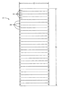
[00042] Referring to FIG. 1, there is shown generally an embodiment of a
full
panel 10 of the present invention, this particular panel being about 27 U in
height 14.
Each piece 16 is uniform in height and width 12, and each piece has two half-
racetrack shaped scoring apertures 18 on the opposite ends of the piece 16.
[00043] Referring to FIG. 2, there is shown a close up view of an
embodiment
of three joined panel pieces 16, where a pair of jagged lines 20 represents a
continuation of the pieces, which has been done to fit the figure onto one
page for
close inspection. Each piece is uniform in height 22 and width 12, and each
piece 16
has two half-racetrack shaped scoring apertures 18 on the opposite ends of the
piece
16. Each aperture 18 is located within the center of the edge of the piece on
which the
aperture resides, such that the measurements 30 from the each of the edges of
the
apertures 18 to the scored edges of the piece on which it resides are
equidistant.
Similarly, the center of the aperture 18 is aligned such that it is halfway
down the
edge of the piece 24. Each aperture is of a uniform length 28 and height 32,
and in a
uniform location throughout all of the pieces 16 of the panel. The apertures
18 on
each piece 16 are equidistant 26 from each other throughout the panel. Each
piece 16
has been scored 34 so as to permit ready separation from adjacent pieces 16.
Each
aperture 18 has been scored 36 so as to permit ready separation from the piece
16 on
which it resides.
[00044] Referring to FIG. 3, there is shown generally another embodiment
of a
full panel 10 of the present invention, this particular panel being about 27 U
in height
14. Each piece 16 is uniform in height and width 12, and each piece has two
rounded
T shaped scoring apertures 38 on the opposite ends of the piece 16.
[00045] Referring to FIG. 4, there is shown a close up view of an
embodiment
of three joined panel pieces 16, where a pair of jagged lines 20 represents a
continuation of the pieces, which has been done to fit the figure onto one
page for
close inspection. Each piece is uniform in height 22 and width 12, and each
piece 16
has two rounded T shaped scoring apertures 38 on the opposite ends of the
piece 16.
Each aperture 38 is located within the center of the edge of the piece on
which the
aperture resides, such that the measurements 30 from the each of the edges of
the
apertures 38 to the scored edges of the piece on which it resides are
equidistant.
9
CA 02697028 2010-02-19
WO 2009/025838
PCT/US2008/009959
Similarly, the center of the aperture 38 is aligned such that it is halfway
down the
edge of the piece 24. Each aperture is of a uniform length 28. Each aperture
is of a
uniform height, both in the narrowest height 40 and in the widest height 42.
Each
aperture is in a uniform location throughout all of the pieces 16 of the
panel. Each
aperture is of a uniform depth 44 from the edge of the piece to the widest
region of the
aperture. Each aperture is of a uniform depth 46 throughout the widest region
of the
aperture. The apertures 38 on each piece 16 are equidistant 26 from each other
throughout the panel. Each piece 16 has been scored 34 so as to permit ready
separation from adjacent pieces 16. Each aperture 38 has been scored 36 so as
to
permit ready separation from the piece 16 on which it resides. In this
particular
embodiment, the scoring 34 between the pieces results in nicks 48 that serve
to hold
the pieces 16 together until perforation. The spacing 50 between the nicks 48
is
uniform in length throughout the perforations between the pieces.
[00046] Referring to FIG. 5, there is shown a close up view of yet another
embodiment of three joined panel pieces 16, where a pair of jagged lines 20
represents a continuation of the pieces, which has been done to fit the figure
onto one
page for close inspection. Each piece is uniform in height 22 and width 12,
and each
piece 16 has two rounded rectangle shaped scoring apertures 52 on the opposite
ends
of the piece 16. Each aperture 52 is located within the center of the edge of
the piece
on which the aperture resides, such that the measurements 30 from the each of
the
edges of the apertures 52 to the scored edges of the piece on which it resides
are
equidistant. Similarly, the center of the aperture 52 is aligned such that it
is halfway
down the edge of the piece 24. Each aperture is in a uniform location
throughout all
of the pieces 16 of the panel. Each aperture is located at a uniform depth 54
from the
edge of the piece to the outermost edge of the aperture. Each aperture is
located at a
uniform depth 62 from the edge of the piece to the innermost edge of the
aperture.
Each aperture is of a uniform height 56. Each aperture is of a uniform width
58. The
apertures 52 on each piece 16 are equidistant 26 from each other throughout
the panel.
The centers of the apertures 52 on each piece 16 are equidistant 60 from each
other
throughout the panel. Each piece 16 has been scored 34 so as to permit ready
separation from adjacent pieces 16. Each aperture 52 has been scored 36 so as
to
permit ready separation from the piece 16 on which it resides. In this
particular
embodiment, the scoring 34 between the pieces results in nicks 48 that serve
to hold
CA 02697028 2010-02-19
WO 2009/025838 PCT/US2008/009959
the pieces 16 together until perforation. The spacing 50 between the nicks 48
is
uniform in length throughout the perforations between the pieces.
[00047] In each embodiment herein, where scoring apertures are present,
regardless of the width of the panel piece, the scoring apertures will
substantially
align with at least two opposing rack holes of an EIA compliant frame.
[00048] In a preferred embodiment, each panel piece has been scored on the
ends of the panel piece, such that a half-racetrack shaped scoring aperture is
present
on each end, each aperture located substantially in the center of the
respective vertical
edges of the piece, each aperture being between about 0.250 to about 0.375
inches =
high, and being located between about 0.625 to about 0.875 inches from the
vertical
edge of the piece on both sides of the aperture, each aperture being about
0.6875
inches deep, measured horizontally from the edge of the piece to the furthest
inside
edge of the aperture.
[00049] In another preferred embodiment, each panel piece has been scored
on
the ends of the panel piece, such that a rounded T shaped scoring aperture is
present
on each end, each aperture located substantially in the center of the
respective vertical
edges of the piece, each aperture being between about 0.200 to about 0.375
inches
high at the narrowest region and being between about 0.300 to about 0.500
inches
high at the highest region. In this preferred embodiment, the apertures are
located
between about 0.300 to about 0.400 inches from the edge of the end of the
piece to the
innermost scoring of the aperture.
[00050] In yet another preferred embodiment, each panel piece has been
scored
on the ends of the panel piece, such that a rounded rectangle shaped scoring
aperture
is present on each end, each aperture located substantially in the center of
the
respective vertical edges of the piece, each aperture being between about
0.350 to
about 0.500 inches high and being between about 0.200 to about 0.375 inches
wide.
In this preferred embodiment, the apertures are located between about 0.725 to
about
0.775 inches from the vertical edge of the piece on both sides of the
aperture. In this
preferred embodiment, each aperture is about 0.6875 inches deep, measured
horizontally from the edge of the piece to the furthest inside edge of the
aperture.
[00051] In a preferred embodiment, the panel pieces have been scored such
that
between the scored pieces results are nicks that serve to hold the pieces
together until
perforation. The spacing between the nicks is uniform in length throughout the
perforations between the pieces, and is preferably between about 0.200 to
about 1.000
11
CA 02697028 2010-02-19
WO 2009/025838
PCT/US2008/009959
inches, more preferably between about 0.250 to about 0.500 inches. In this
preferred
embodiment, the nicks are of a uniform length throughout the perforations
between
the pieces, and are preferably between about 0.15625 to about 0.250 inches in
length,
and are preferably about 0.03125 inches in length.
[00052] In a preferred embodiment, each panel piece has been scored three
times on each of the ends of the panel piece, such that a series of three
scoring
apertures are present on each end, each aperture located equidistant from the
two most
adjacent scorings, whether those scorings are for an adjacent aperture or a
scoring
between two panel pieces, or the edge of the panel.
[00053] In a preferred embodiment, each panel piece has been scored three
times on each of the ends of the panel piece, such that a series of three half-
racetrack
shaped scoring apertures are present on each end, each aperture located
equidistant
from the two most adjacent scorings, whether those scorings are for an
adjacent
aperture or a scoring between two panel pieces, or the edge of the panel. In
this
preferred embodiment, each aperture is between about 0.250 to about 0.375
inches
high, and is about 0.6875 inches deep, measured horizontally from the edge of
the
piece to the furthest inside edge of the aperture.
[00054] In a particularly preferred embodiment of the present invention,
the
system comprises a 27 U panel, where the panel is about 19.25 inches wide, and
is
about 47.25 inches high. In this particularly preferred embodiment, the panel
has
been scored such that each piece of the panel may be readily separated from
the
pieces directly adjacent to each piece, and has been scored so as to
substantially
prevent air flow through the scoring. In this particularly preferred
embodiment, each
panel piece has been additionally scored on the ends of the panel piece, such
that a
half-racetrack shaped scoring aperture is present on each end, each aperture
located
substantially in the center of the respective vertical edges of the piece,
each aperture
being about 0.250 inches high, and being located about 0.875 inches from the
vertical
edge of the piece on both sides of the aperture, each aperture being about
0.6875
inches deep, measured horizontally from the edge of the piece to the furthest
inside
edge of the aperture. In this particularly preferred embodiment, the panel has
been
scored such that each half-racetrack shaped scoring aperture may be readily
separated
from the pieces on which it resides, and has been scored so as to
substantially prevent
air flow through the scoring.
12
CA 02697028 2010-02-19
WO 2009/025838
PCT/US2008/009959
[00055] As used herein, and as would be understood by those of ordinary
skill
in the art, the term "rounded rectangle" refers to a shape that is
substantially
rectangular, which includes a shape that is square, where the four corners
have been
rounded into equal arcical segments of ninety degrees.
[00056] As used herein, and as would be understood by those of ordinary
skill
in the art, the term "rounded T" refers to a shape that comprises two
substantially
perpendicular line segments of some width greater than zero, where one line
segment
terminates at the midpoint of the other line segment, and where at least two
corners
have been rounded into equal arcical segments of ninety degrees. In an
embodiment
of the term "rounded T", all of the corners have been rounded into equal
arcical
segments of ninety degrees. In an embodiment of the term "rounded T", the two
line
segments are of about equal length.
[00057] The present invention additionally includes a kit, where the kit
comprises at least one server rack blanking panel of the present invention and
additionally mounting equipment known by those of ordinary skill in the art,
such as
brackets, screws, pins, pegs, bolts, hooks and other similar equipment. The
mounting
equipment may be readily attached to the server rack blanking panel or pre-
attached
thereto, and may be attached either permanently or removably.
[00058] As can be seen by the embodiments and drawings disclosed herein,
the
present invention permits the easy and flexible application of the invention
to empty
server rack space. For example, on a typical server rack that is 46 U in
height, where
the top ten U are empty, and where computer equipment, including potentially
servers, occupy the remainder of the rack, a section of the panel may be
separated
such that a sub-panel of ten panel pieces is removed from the remainder of the
panel
along the desired scored perforations. In this example, where each panel piece
has
one half-racetrack shaped scoring aperture on each end, these scoring
apertures on the
two opposite end pieces of this sub-panel may be removed along the scored
perforations of those apertures, and potentially additional apertures may be
so
removed as desired. In this example, the sub-panel may then be affixed to the
open
space of the server rack, either on the front or the back of the rack, so as
to prevent air
flow from the rear of the equipment on the server rack from migrating to the
front of
the equipment on the server rack through the server rack. In this example, the
sub-
panel may be so affixed in a manner known by those skilled in the art,
including those
disclosed herein.
13
CA 02697028 2010-02-19
WO 2009/025838
PCT/US2008/009959
[00059] While specific embodiments have been shown and described, many
variations are possible. The particular shape of the segments and scored lines
and
markings, scoring depths and aperture outlines including all horizontal and
vertical
orientations, dimensions and thicknesses may be changed as desired to suit the
particular server rack with which the invention is used. The material and its
configuration and number of segments may vary although preferred embodiments
are
shown and described. The terms, descriptions and figures used herein are set
forth by
way of illustration only and are not meant as limitations. Those of ordinary
skill in
the art will recognize that many variations are possible within the scope of
the
invention, which is intended to be defined by the disclosure herein and their
equivalents, in which all terms are meant in their broadest reasonable sense
unless
otherwise indicated.
14