Language selection

Search

Patent 2697121 Summary

Third-party information liability

Some of the information on this Web page has been provided by external sources. The Government of Canada is not responsible for the accuracy, reliability or currency of the information supplied by external sources. Users wishing to rely upon this information should consult directly with the source of the information. Content provided by external sources is not subject to official languages, privacy and accessibility requirements.

Claims and Abstract availability

Any discrepancies in the text and image of the Claims and Abstract are due to differing posting times. Text of the Claims and Abstract are posted:

  • At the time the application is open to public inspection;
  • At the time of issue of the patent (grant).
(12) Patent: (11) CA 2697121
(54) English Title: INTENTIONALLY MISTUNED INTEGRALLY BLADED ROTOR
(54) French Title: ROTOR A AUBES INTENTIONNELLEMENT DESACCORDEES DE FACON INTEGRALE
Status: Granted
Bibliographic Data
(51) International Patent Classification (IPC):
  • F01D 5/16 (2006.01)
  • F01D 5/14 (2006.01)
  • F01D 5/34 (2006.01)
  • F02C 7/00 (2006.01)
(72) Inventors :
  • KELLY, FRANK (Canada)
  • HEIKURINEN, KARI (Canada)
  • FAZARI, EDWARD (Canada)
  • WU, YUHUA (Canada)
(73) Owners :
  • PRATT & WHITNEY CANADA CORP. (Canada)
(71) Applicants :
  • PRATT & WHITNEY CANADA CORP. (Canada)
(74) Agent: NORTON ROSE FULBRIGHT CANADA LLP/S.E.N.C.R.L., S.R.L.
(74) Associate agent:
(45) Issued: 2013-04-09
(22) Filed Date: 2010-03-17
(41) Open to Public Inspection: 2010-09-26
Examination requested: 2010-03-17
Availability of licence: N/A
(25) Language of filing: English

Patent Cooperation Treaty (PCT): No

(30) Application Priority Data:
Application No. Country/Territory Date
12/411,644 United States of America 2009-03-26

Abstracts

English Abstract

A frequency mistuned integrally bladed rotor (IBR) for a gas turbine engine comprises a hub and a circumferential row of blades of varying frequency projecting integrally from the hub. Each blade in the row alternate with another blade having a different pressure surface definition but similar suction surface, leading edge and trailing edge definitions.


French Abstract

Un rotor à aubes désaccordées de façon intégrale pour une turbine à gaz comporte un moyeu et une rangée circulaire d'aubes à fréquence variable faisant saillie intégralement à partir du moyeu. Chaque aube dans la rangée alterne avec une autre aube ayant une définition de surface de pression différente, mais des définitions de surface d'aspiration, de bord d'attaque et de bord de fuite similaires.

Claims

Note: Claims are shown in the official language in which they were submitted.


WHAT IS CLAIMED IS:

1. An integrally bladed rotor (IBR) for a gas turbine engine, comprises a hub
and
a circumferential row of blades projecting integrally from said hub, the row
including
an even number of blades alternating between blades having first and second
airfoil
definitions around the hub, each blade having a pressure side and a suction
side
disposed on opposed sides of a median axis and extending between a trailing
edge
and a leading edge, the first and second airfoil definitions being different
and having
respective pressure side thicknesses T1 and T2 defined between respective
median
axes and respective pressure sides of the blades, the pressure side thickness
T1 of the
first airfoil definition being greater than the pressure side thickness T2 of
the second
airfoil definition, the first and second air foil definitions having a same
suction
surface profile.

2. The IBR defined in claim 1, wherein the first and second airfoil
definitions
also have a same leading edge and trailing edge profile but a different
pressure
surface profile.

3. The IBR defined in claim 1, wherein a first interblade passage defined
between the pressure side of a first blade having the first airfoil definition
and the
suction side of an adjacent blade having the second airfoil definition has a
smaller
passage section than that of a second interblade passage defined between the
pressure
side of the adjacent blade and the suction side of a next blade having the
first airfoil
definition, thereby providing for alternate small and large interblade
passages around
the hub.

4. The IBR defined in claim 1, wherein the natural frequency of the blades
having the pressure side thickness T1 differs from the natural frequency of
the blades
having the pressure side thickness T2 by at least 3% and up to 10%.

5. The IBR defined in claim 1, wherein the difference in thickness between T1
and T2 is provided over substantially the full span of the blades.

-6-


6. The IBR defined in claim 1, wherein the first airfoil definition is thicker
than
the second airfoil definition between the leading edge and the trailing edge
of the
blades.

7. A frequency mistuned integrally bladed rotor (IBR) for a gas turbine
engine,
comprising a hub and a circumferential row of blades of varying frequency
projecting
integrally from the hub, the row including an even number of blades, each
blade in
the row alternates with another blade having a different pressure surface
definition
but substantially identical suction surface, leading edge and trailing edge
definitions.
8. The mistuned IBR defined in claim 7, wherein the circumferential row of
blades includes a first group of blades and a second group of blades disposed
in an
alternating pattern around the hub, the blades of the first and second groups
of blades
having corresponding first and second blades sections over the full span of
the blades,
the corresponding first and second blades sections when superposed having
coincident suction side, leading edge and trailing edge outlines but a
different
pressure side outline, the pressure side outline of the first blade section
being offset
outwardly from the corresponding pressure side outline of the second blade
section
along at least a chord-wise portion of the blades.

9. The mistuned IBR defined in claim 8, wherein the offset extends over
substantially a full span of the blades.

10. The mistuned IBR defined in claim 8, wherein the offset between the
pressure
side outlines of the first and second corresponding blade sections is provided
between
the leading edge and the trailing edge of the blades.

11. The mistuned IBR defined in claim 8, wherein the blades of the first group
of
blades have a thicker pressure side than that of the blades of the second
group of
blades.


-7-


12. The mistuned IBR defined in claim 8, wherein the blades of the first group
of
blades have a natural frequency which differs from the natural frequency of
the
blades of the second group of blades by at least 3% and up to 10%.

13. A method of reducing vibration in an gas turbine engine integrally bladed
rotor (IBR) having a circumferential row of blades extending integrally from a
hub,
the circumferential row of blades comprising an even number of blades; the
method
comprising varying the natural frequency of the blades around the hub in an
alternate
pattern by providing first and second distinct airfoil profiles around the
hub, the first
and second profiles having similar suction side, leading edge and trailing
edge
profiles but a different pressure side profile.


-8-

Description

Note: Descriptions are shown in the official language in which they were submitted.


CA 02697121 2010-03-17

INTENTIONALLY MISTUNED INTEGRALLY BLADED ROTOR
TECHNICAL FIELD

The application relates generally to gas turbine engines and, more
particularly, to a frequency mistuned integrally bladed rotor (IBR).
BACKGROUND OF THE ART

Integrally bladed rotors (IBR), also known as blisks, comprises a
circumferential row of blades integrally formed in the periphery of a hub. The
blades
in the row are typically machined such as to have the same airfoil shape.
However, it

has been found that the uniformity between the blades increases flutter
susceptibility.
Flutter may occur when two or more adjacent blades in a blade row vibrate at a
frequency close to their natural vibration frequency and the vibration motion
between
the adjacent blades is substantially in phase.

One solution proposed in the past to avoid flutter instability is to mistune
the
IBR by cropping the leading edge tip of some of the blades around the hub.
However,
this solution is not fully satisfactory from an aerodynamic and a
manufacturing point
of view.

Accordingly, there is a need to provide a new frequency mistuning method
suited for integrally bladed rotors.

SUMMARY

It is therefore an object to provide an integrally bladed rotor (IBR) for a
gas
turbine engine, comprises a hub and a circumferential row of blades projecting
integrally from said hub, the row including an even number of blades
alternating
between blades having first and second airfoil definitions around the hub,
each blade
having a pressure side and a suction side disposed on opposed sides of a
median axis
and extending between a trailing edge and a leading edge, the first and second
airfoil
definitions being different and having respective pressure side thicknesses Ti
and T2
defined between respective median axes and respective pressure sides of the
blades,
-1-


CA 02697121 2010-03-17

the pressure side thickness Ti of the first airfoil definition being greater
than the
pressure side thickness T2 of the second airfoil definition.

In another aspect, there is provided a frequency mistuned integrally bladed
rotor (IBR) for a gas turbine engine, comprising a hub and a circumferential
row of
blades of varying frequency projecting integrally from the hub, the row
including an
even number of blades, each blade in the row alternate with another blade
having a
different pressure surface definition but substantially identical suction
surface,
leading edge and trailing edge definitions.

In a third aspect, there is provided a method of reducing vibration in an gas
turbine engine integrally bladed rotor (IBR) having a circumferential row of
blades
extending integrally from a hub, the circumferential row of blades comprising
an
even number of blades; the method comprising varying the natural frequency of
the
blades around the hub in an alternate pattern by providing first and second
distinct
airfoil profiles around the hub, the first and second profiles having similar
suction
side, leading edge and trailing edge profiles but a different pressure side
profile.

DESCRIPTION OF THE DRAWINGS

Reference is now made to the accompanying figures, in which:

Fig. 1 is a schematic cross-sectional view of a turbofan gas turbine engine;
Fig. 2 is an isometric view of a frequency mistuned integrally bladed rotor
(IBR) suited for use as a fan or compressor rotor of the gas turbine engine
shown in
Fig. 1; and

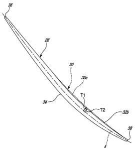
Fig. 3 is a cross-section view illustrating two distinct blade sections
superposed one over the other to show the differences between the pressure
side
profiles thereof.

DETAILED DESCRIPTION
Fig.1 illustrates a turbofan gas turbine engine 10 of a type preferably
provided for use in subsonic flight, generally comprising in serial flow
communication a fan 12 through which ambient air is propelled, a multistage
-2-


CA 02697121 2010-03-17

compressor 14 for pressurizing the air, a combustor 16 in which the compressed
air is
mixed with fuel and ignited for generating an annular stream of hot combustion
gases, and a turbine section 18 for extracting energy from the combustion
gases.

Fig. 2 illustrates an integrally bladed rotor (IBR) 20 that could be used in
the
fan or compressor section of the engine 10 shown in Fig. 1. The IBR 20 has a
hub 22
and a circumferential row of blades 24 extending integrally from the hub 22,
the
adjacent blades defining interblade passages 26 for the working fluid. The hub
22 and
the blade row 24 can be flank milled or point milled from a same block of
material.

The blade row 24 has an even number of blades and is composed of two
groups of blades 28 and 30 which are designed to have different natural
vibration
frequencies in order to avoid flutter instability. The blades 28 and 30 are
disposed in
an alternate fashion around the hub 22. The difference in frequency between
blades
28 and 30 results from the blades 28 and 30 having different airfoil
geometries. More
particularly, the blades 28 and 30 can be mistuned relative to one another by
milling a

different surface geometry in the pressure side 32 of blades 30. The
differences
between the airfoil geometries of blades 28 and 30 can be better illustrated
by
superposing an airfoil section of one of the first group of blades 28 over a
corresponding airfoil section of one of the blades of the second group of
blades 30, as
for instance shown in Fig. 3.

Referring to Fig. 3, it can seen that both groups of blades 28 and 30 have
substantially the same suction surface 34, leading edge 36 and trailing edge
38
definitions (i.e. in the example the suction surface, the trailing edge and
the leading
edge contour or outline of the blades 28 and 30 coincide with each other when
corresponding sections are superposed one over the other). The suction
surface,
leading edge and trailing edge definitions of the blades 28 and 30 are
substantially
identical along all of the length or span of the blades 28 and 30 (i.e. from
the tip to
the root of the blades). However, it can be appreciated that the pressure
surface 32 of
the blades 28 and 30 do not coincide along all the chord of the blades. The
pressure
surface 32a of blade 30 diverges from the pressure surface 32b of blade 28 at
a

location that can be anywhere from the leading edge to the trailing edge (in
the
illustrated example: slightly upstream from a mid-chord area of the blades
relative to
-3-


CA 02697121 2010-03-17

a flow direction of the working fluid). The pressure surface 32a of blade 30
is thicker
than the pressure surface 32b of blade 28. The thickening is provided along
the full
length or span of the blades 30 that is from the root to the tip of the
blades.

The thickness of the pressure surface 32 of the blades 28 and 30 can be
defined by the distance of the pressure surface from a chord-wise median axis
A of
the blades. As can be appreciated from Fig. 3, the pressure surface thickness
T1 of
blade 30 is greater than the pressure surface thickness T2 of blade 28. The
additional
amount of material left on the pressure side 32 of the blade 30 is selected
such that
the natural frequency of blade 30 is different from the natural frequency of
blades 28

by at least 3% up to 10%. One advantage of varying the pressure surface as
opposed ,
for instance, to cropping the leading edge is to minimise the negative impact
on the
rotor performance. Cropping reduces the working surface area of the blade.

The thickening of the pressure side 32a of the blades 30 reduces the cross-
section area of every other interblade passage 26 around the hub 22 of the IBR
20.
Indeed, the flow passage area between the pressure surface 32b of a first one
of the

blades 28 and the suction surface 34 of the adjacent blade 30 is greater than
the flow
passage area of the pressure surface 32a of this adjacent blade 30 and the
suction
surface 34 of the next blade 28.

The intentional mistuning of the blades 28 and 30 provides passive flutter
control by changing both mechanical and aerodynamic blade-to-blade energy
transfer
of the IBR during the full range of the gas turbine engine operation. The
mistuning of
blades 28 and 30 makes it more difficult for the blades to vibrate at the same
frequency, thereby reducing flutter susceptibility. This provides for two
different
airfoil definitions incorporated into one component.

Thickening the pressure surface of the blades allows to effectively mistuning
the blades of the IBR in order to avoid flutter instability and that without
negatively
affecting the aerodynamic efficiency of the IBR and still providing for easy
manufacturing of the IBRs. This approach has also been found been found
satisfactory from a structural point of view.

-4-


CA 02697121 2010-03-17

The above description is meant to be exemplary only, and one skilled in the
art will recognize that changes may be made to the embodiments described
without
departing from the scope of the invention disclosed. Other modifications which
fall
within the scope of the present invention will be apparent to those skilled in
the art,

in light of a review of this disclosure, and such modifications are intended
to fall
within the appended claims.

-5-

Representative Drawing
A single figure which represents the drawing illustrating the invention.
Administrative Status

For a clearer understanding of the status of the application/patent presented on this page, the site Disclaimer , as well as the definitions for Patent , Administrative Status , Maintenance Fee  and Payment History  should be consulted.

Administrative Status

Title Date
Forecasted Issue Date 2013-04-09
(22) Filed 2010-03-17
Examination Requested 2010-03-17
(41) Open to Public Inspection 2010-09-26
(45) Issued 2013-04-09

Abandonment History

There is no abandonment history.

Maintenance Fee

Last Payment of $263.14 was received on 2023-12-14


 Upcoming maintenance fee amounts

Description Date Amount
Next Payment if small entity fee 2025-03-17 $253.00
Next Payment if standard fee 2025-03-17 $624.00

Note : If the full payment has not been received on or before the date indicated, a further fee may be required which may be one of the following

  • the reinstatement fee;
  • the late payment fee; or
  • additional fee to reverse deemed expiry.

Patent fees are adjusted on the 1st of January every year. The amounts above are the current amounts if received by December 31 of the current year.
Please refer to the CIPO Patent Fees web page to see all current fee amounts.

Payment History

Fee Type Anniversary Year Due Date Amount Paid Paid Date
Request for Examination $800.00 2010-03-17
Application Fee $400.00 2010-03-17
Maintenance Fee - Application - New Act 2 2012-03-19 $100.00 2012-01-16
Final Fee $300.00 2013-01-16
Maintenance Fee - Application - New Act 3 2013-03-18 $100.00 2013-01-16
Maintenance Fee - Patent - New Act 4 2014-03-17 $100.00 2014-02-14
Maintenance Fee - Patent - New Act 5 2015-03-17 $200.00 2015-02-25
Maintenance Fee - Patent - New Act 6 2016-03-17 $200.00 2016-02-19
Maintenance Fee - Patent - New Act 7 2017-03-17 $200.00 2017-02-22
Maintenance Fee - Patent - New Act 8 2018-03-19 $200.00 2018-02-21
Maintenance Fee - Patent - New Act 9 2019-03-18 $200.00 2019-02-21
Maintenance Fee - Patent - New Act 10 2020-03-17 $250.00 2020-02-21
Maintenance Fee - Patent - New Act 11 2021-03-17 $255.00 2021-02-18
Maintenance Fee - Patent - New Act 12 2022-03-17 $254.49 2022-02-18
Maintenance Fee - Patent - New Act 13 2023-03-17 $263.14 2023-02-21
Maintenance Fee - Patent - New Act 14 2024-03-18 $263.14 2023-12-14
Owners on Record

Note: Records showing the ownership history in alphabetical order.

Current Owners on Record
PRATT & WHITNEY CANADA CORP.
Past Owners on Record
FAZARI, EDWARD
HEIKURINEN, KARI
KELLY, FRANK
WU, YUHUA
Past Owners that do not appear in the "Owners on Record" listing will appear in other documentation within the application.
Documents

To view selected files, please enter reCAPTCHA code :


To view images, click a link in the Document Description column. To download the documents, select one or more checkboxes in the first column and then click the "Download Selected in PDF format (Zip Archive)" or the "Download Selected as Single PDF" button.

List of published and non-published patent-specific documents on the CPD .

If you have any difficulty accessing content, you can call the Client Service Centre at 1-866-997-1936 or send them an e-mail at CIPO Client Service Centre.


Document
Description 
Date
(yyyy-mm-dd) 
Number of pages   Size of Image (KB) 
Cover Page 2010-09-15 1 31
Abstract 2010-03-17 1 10
Description 2010-03-17 5 208
Claims 2010-03-17 3 104
Drawings 2010-03-17 3 64
Representative Drawing 2010-08-31 1 4
Claims 2012-04-17 3 105
Cover Page 2013-03-14 1 31
Assignment 2010-03-17 8 239
Prosecution-Amendment 2011-10-25 2 63
Prosecution-Amendment 2012-04-17 5 207
Correspondence 2013-01-16 2 65