Note: Descriptions are shown in the official language in which they were submitted.
CA 02697220 2010-03-19
SYSTEM AND METHOD FOR RETURN ELECTRODE MONITORING
BACKGROUND
Technical Field
The present disclosure relates to electrosurgical apparatuses, systems and
methods. More
particularly, the present disclosure is directed to electrosurgical systems
configured to monitor
contact quality of return electrode pads to the patient during electrosurgical
procedures.
Background of Related Art
Energy-based tissue treatment is well known in the art. Various types of
energy (e.g.,
electrical, ultrasonic, microwave, cryogenic, heat, laser, etc.) are applied
to tissue to achieve a
desired result. Electrosurgery involves application of high radio frequency
electrical current to a
surgical site to cut, ablate, coagulate or seal tissue. In monopolar
electrosurgery, the active
electrode is typically a part of the surgical instrument held by the surgeon
that is applied to the
tissue to be treated. A patient return electrode is placed remotely from the
active electrode to
carry the current back to the generator and safely disperse current applied by
the active electrode.
The return electrodes usually have a large patient contact surface area to
minimize
heating at that site. Heating is caused by high current densities which
directly depend on the
surface area. A larger surface contact area results in lower localized heat
intensity. Return
electrodes are typically sized based on assumptions of the maximum current
utilized during a
particular surgical procedure and the duty cycle (i.e., the percentage of time
the generator is on).
1
CA 02697220 2010-03-19
The first types of return electrodes were in the form of large metal plates
covered with
conductive gel. Later, adhesive electrodes were developed with a single metal
foil covered with
conductive gel or conductive adhesive. However, one problem with these
adhesive electrodes
was that if a portion peeled from the patient, the contact area of the
electrode with the patient
decreased, thereby increasing the current density at the adhered portion and,
in turn, increasing
the heating at the tissue. This risked burning the patient in the area under
the adhered portion of
the return electrode if the tissue was heated beyond the point where
circulation of blood could
cool the skin.
To address this problem various return electrodes and hardware circuits,
generically
called Return Electrode Contact Quality Monitors (RECQMs), were developed.
Such systems
relied on measuring impedance at the return electrode to calculate a variety
of tissue and/or
electrode properties. These systems detected peeling by identifying changes in
impedance of the
return electrodes.
SUMMARY
According to one embodiment of the present disclosure, a detection circuit for
return
electrode monitoring is disclosed. The detection circuit includes a
transformer operatively
coupled to a pair of split electrode pads, wherein the transformer is
configured to transceive a
return electrode sense signal. The detection circuit also includes a first
switch coupled to the
transformer and a neutrally-referenced second switch, wherein the first switch
and the second
switch are disposed on a single die. The detection circuit further includes an
operational
2
CA 02697220 2010-03-19
amplifier coupled to the first switch and the neutrally-referenced second
switch. The operational
amplifier is configured to subtract a noise signal from the return electrode
sense signal.
According to another embodiment of the present disclosure, a return electrode
monitoring
system is disclosed. The system includes a return electrode pad including one
pair of split
electrode pads and a detection circuit having a transformer operatively
coupled to the pair of split
electrode pads, wherein the transformer is configured to transceive a return
electrode sense
signal. The detection circuit also includes a first switch coupled to the
transformer and a
neutrally-referenced second switch, wherein the first switch and the second
switch are disposed
on a single die and generate substantially similar switch noise signals. The
system also includes
an operational amplifier coupled to the at least one first switch and the at
least one neutrally-
referenced second switch. The operational amplifier configured to cancel out
the switch noise
signals from the return electrode sense signal.
According to a further embodiment of the present disclosure a return electrode
monitoring system is disclosed. The system includes a return electrode pad
having one or more
pairs of split electrode pads and a detection circuit having a single-ended
primary transformer
operatively coupled to the pair of split electrode pads, wherein the single-
ended primary
transformer is configured to transceive a return electrode sense signal. The
detection circuit also
includes a switch package including a first switch coupled to the single-ended
primary
transformer and a neutrally-referenced second switch, wherein the first switch
and the second
switch generate substantially similar switch noise signals. The detection
circuit also includes an
operational amplifier coupled to the switch package. The operational amplifier
is configured to
subtract the switch noise signals from the return electrode sense signal. The
system also includes
3
CA 02697220 2010-03-19
a controller coupled to the detection circuit and configured to analyze the
noise-cancelled return
electrode sense signal.
BRIEF DESCRIPTION OF THE DRAWINGS
Various embodiments of the present disclosure are described herein with
reference to the
drawings wherein:
Fig. 1 is a schematic block diagram of an electrosurgical system according to
one
embodiment of the present disclosure;
Fig. 2 is a schematic block diagram of a generator according to an embodiment
of the
present disclosure; and
Fig. 3 is a schematic circuit diagram of a detection circuit according to an
embodiment of
the present disclosure.
DETAILED DESCRIPTION
Particular embodiments of the present disclosure are described hereinbelow
with
reference to the accompanying drawings. In the following description, well-
known functions or
constructions are not described in detail to avoid obscuring the present
disclosure in unnecessary
detail.
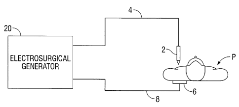
Fig. 1 is a schematic illustration of an electrosurgical system according to
one
embodiment of the present disclosure. The system includes an electrosurgical
instrument 2,
which is a monopolar instrument including one or more active electrodes (e.g.,
electrosurgical
4
CA 02697220 2010-03-19
cutting probe, ablation electrode(s), etc.) for treating tissue of a patient
P. Electrosurgical RF
energy is supplied to the instrument 2 by a generator 20 via an
electrosurgical cable 4 connected
to an active output terminal that allows the instrument 2 to coagulate, ablate
and/or otherwise
treat tissue. The energy is returned to the generator 20 through a return
electrode pad 6 via a
return cable 8. The system may include a plurality of return electrodes pads 6
arranged to
minimize the chances of tissue damage by maximizing the overall contact area
with the patient P.
In addition, the generator 20 and the return electrode 6 may be configured for
monitoring so-
called "tissue-to-patient" contact to insure that sufficient contact exists
therebetween to further
minimize chances of tissue damage.
The generator 20 may include input controls (e.g., buttons, activators,
switches, touch
screen, etc.) for controlling the generator 20. In addition, the generator 20
may include one or
more display screens for providing the user with variety of output information
(e.g., intensity
settings, treatment complete indicators, etc.). The input controls allow the
user to adjust power
of the RF energy, waveform, and other parameters to achieve the desired
electrosurgical output
suitable for a particular task (e.g., coagulating, cauterizing, etc.). The
instrument 2 may also
include a plurality of input controls that may be redundant with certain input
controls of the
generator 20. Placing the input controls at the instrument 2 allows for easier
and faster
modification of RF energy parameters during the surgical procedure without
requiring interaction
with the generator 20.
Fig. 2 shows a schematic block diagram of the generator 20 having a controller
24, a high
voltage DC power supply 27 ("HVPS") and an RF output stage 28. The HVPS 27
provides high
voltage DC power to an RF output stage 28, which then converts high voltage DC
power into RF
5
CA 02697220 2010-03-19
energy and delivers the RF energy to the active electrode. In particular, the
RF output stage 28
generates suitable waveforms of high RF energy. The RF output stage 28 is
configured to
generate a plurality of waveforms having various duty cycles, peak voltages,
crest factors, and
other parameters,
The controller 24 includes a microprocessor 25 operably connected to a memory
26,
which may be volatile type memory (e.g., RAM) and/or non-volatile type memory
(e.g., flash
media, disk media, EPROM, etc.). The microprocessor 25 includes an output port
that is
operably connected to the HVPS 27 and/or RF output stage 28 that allows the
microprocessor 25
to control the output of the generator 20 according to either open and/or
closed control loop
schemes. Those skilled in the art will appreciate that the microprocessor 25
may be substituted
by any logic processor (e.g., control circuit) adapted to perform the
calculations discussed herein.
The generator 20 includes a return electrode monitoring ("REM") system 50
having a
detection circuit 22 which is coupled to a pair of split electrode pads, a
first electrode pad 41 and
a second electrode pad 42 disposed within the return electrode pad 6. The
return electrode pad 6
is in contact with the patient P and returns the electrosurgical energy to the
generator 20 via the
first and second electrode pads 41 and 42 coupled to leads 51 and 52,
respectively. In one
embodiment, the return electrode pad 6 may include a plurality of split
electrode pads arranged in
pairs that are coupled to a corresponding number of leads. The leads 51 and 52
are enclosed in a
return cable 8 and are terminated at a secondary winding 44 of a transformer
43. The leads 51
and 52 are interconnected by capacitors 45 and 46. A return lead 48 is coupled
between the
capacitors 45 and 46 and is adapted to return the electrosurgical energy to
the RF output stage 28.
6
CA 02697220 2010-03-19
The transformer 43 of the REM system 50 also includes a primary winding 47
that is connected
to the detection circuit 22.
The controller 24 provides a drive signal, REM CLK, at a specific
interrogation frequency
to the detection circuit 22. REM CLK, is a clock signal generated by the
controller 24 at the
specific frequency, which may be either a square wave, a sine wave, an impulse
or step signal.
REM CLK may be a constant, physiologically benign waveform (e.g., 140 kHz, 2
mA) that the
detection circuit 22 applies to the first electrode pad 41. The drive signal
thereafter passes
through the patient and is returned to the circuit 22 via the second electrode
pad 42. The
detection circuit 22 then measures a response signal to the drive signal and
monitors the changes
in the response signal to determine degree of adhesion of the return electrode
pad 6.
The response signal (e.g., returning drive signal) is modified by the
impedance of the first
and second electrode pads 41 and 42. More specifically, as the impedance
between the split
electrode pads 41 and 42 changes due to peeling of the return electrode pad 6
from the patient,
the detection circuit 22 then supplies the impedance measurement to the
controller 24, which
determines whether the impedance is within a desired range. If the impedance
is outside the
desired range an excessive peeling condition exists with the return electrode
pad 6 and the
controller 24 issues an alarm and/or adjusts the output of the generator 20
(e.g., terminates RF
energy supply).
With reference to Fig. 3, the detection circuit 22 is coupled to the primary
winding 47 of
the transformer 43 and the secondary winding 44 is coupled to the return
electrode pad 6. The
primary winding 47 is in a single-ended primary configuration, in which the
primary winding 47
7
CA 02697220 2010-03-19
is referenced to the ground and includes a single-ended line 56. The primary
winding 47 is also
coupled to an input from the controller 24 for transmitting the REM CLK signal
therethrough.
The detection circuit 22 also includes a first switch 60 and a second switch
62 that are
operated by the REM CLK. The first and second switches 60 and 62 are analog
switches
disposed on the same switch package 61 (e.g., being disposed on a single die).
The first switch
60 is coupled to the single-ended line 56 of the primary winding 47. The
switches 60 and 62 are
operated at the REM CLK frequency. When the first switch 60 is open the REM
sense signal
from the electrode pad 6 is transmitted therethrough to the controller 24. The
second switch 62 is
neutrally-referenced to a ground and when the second switch 62 is open, only
the noise
introduced by charge injection is produced. The first and second switches 60
and 62 may be
transistors, such as complementary metal-oxide-semiconductor field-effect
transistors (CMOS),
metal-oxide-semiconductor field-effect transistors (MOSFET), junction field-
effect transistors
(JFET) and the like.
When the first and second switches 60 and 62 are operated, a small electric
charge, so-
called "charge injection," is introduced into the signal when the switch is
closed. Thus, the REM
sense signal from the return electrode pad 6 is contaminated by the noise from
the charge
injection of the first switch 60. Charge injection is not a desirable feature
of analog switches as
manufacturers are always striving to reduce its effect. However, during analog
switch
manufacture, charge injection is not a well-controlled process parameter,
making it difficult to
produce switches having specific charge injection. Calibration for specific
charge injection is
also problematic. Manufacturers may modify the charge injection parameters of
the switches
without notice, e.g., due to a change in manufacturing process, which requires
recalibration to
8
CA 02697220 2010-03-19
account for the change in the charge injection. However, if a package or die
including multiple
switches is used, the charge injection across the switches of that package is
substantially similar.
Without being restricted by a particular theory, it is believed that having
two corresponding
switches, e.g., first and second switches 60 and 62, being disposed on the
same switch package
61 provides for switches that share substantially similar operating
characteristics, such as charge
injection.
The present disclosure provides for a system for elimination of noise from the
REM sense
signal as transmitted through the first switch 60. Since the noise produced by
the first and
second switches 60 and 62 is the same, the noise component may be canceled by
differentiating
the noisy neutrally-referenced signal from the noisy REM sense signal (e.g.,
having switch
noise). More specifically, since the second switch 62 is neutrally-referenced,
the signal produced
therefrom includes only the noise component.
In one embodiment of the present disclosure, the switch package 61 having the
first and
second switches 60 and 62 is disposed on a single die eliminates the noise.
The first and second
switches 60 and 62 are coupled via lines 64 and 66, respectively, to a
differential amplifier 68.
The differential amplifier 68 may be any type of an averaging operational
amplifier. In
particular, the signals from the first and second switches 60 and 62 are
applied to RC circuits 70
and 72, respectively. Each of the RC circuits 70 and 72 include a resistor and
a capacitor
connected in parallel. The RC circuits 70 and 72 connected in this manner
provide an integrating
or an averaging function that converts the AC REM sense signal into a
proportional DC signal.
The signals appearing across the RC circuits 70 and 72 are then applied to the
differential
amplifier 68, which subtracts the noisy neutrally references signal from the
second switch 62
9
CA 02697220 2010-03-19
from the noisy REM sense signal from the first switch 60, thereby canceling
out the noise
signals. Since the first and second switches 60 and 62 are disposed on the
same die the noise
component is the same in each of the signals, the differential amplifier 68
outputs a noise-
cancelled REM sense signal. The REM signal is transmitted to the controller
24, which
determines whether the DC voltage (e.g., from the RC circuits 70 and 72) that
is proportional to
the REM impedance is within a predetermined range. If the impedance is outside
the
predetermined range, an excessive peeling condition exists and the controller
24 issues an alarm
and/or adjusts the output of the generator 20 (e.g., terminates RF energy
supply).
In one embodiment, the detection circuit 22 may include a plurality of first
switches 60
and a plurality of corresponding second switches 62. In this embodiment, the
pairs of first and
second switches 60 and 62 may be disposed on the same switch package 61 as
shown in Fig. 3 or
alternatively, multiple first and corresponding switches 60 and 62, e.g., four
switches, with two
pairs of switches 60 and 62, may be disposed on the same switch package 61.
While several embodiments of the disclosure have been shown in the drawings
and/or
discussed herein, it is not intended that the disclosure be limited thereto,
as it is intended that the
disclosure be as broad in scope as the art will allow and that the
specification be read likewise.
Therefore, the above description should not be construed as limiting, but
merely as
exemplifications of particular embodiments. Those skilled in the art will
envision other
modifications within the scope and spirit of the claims appended hereto.