Note: Descriptions are shown in the official language in which they were submitted.
CA 02697251 2010-02-22
WO 2008/052244 PCTlAU2007/001530
1
TITLE: CONVEYOR SKIRT HANGER
BACKGROUND OF THE INVENTION
1. Field of the Invention
THIS INVENTION relates to a conveyor skirt hanger.
The invention is particularly suitable for, but not limited to, a
skirt hanger for elastomeric-material skirts provided along conveyor belts.
2. Prior Art
The use of skirts along conveyor belts, to limit the egress of the
material being conveyed on the conveyor belt to the atmosphere is well
known; and the skirts are used in compliance with ever-increasing
environmental regulations.
The skirts may be hingedly mounted on the hangers; or the
skirts may be formed of flexible material such as elastomers (eg., fibre-
reinforced rubber or plastics material); and be adjustably mounted in the
hangers to compensate for the wearing of the skirts by the passage of the
conveyor belts.
Examples of the prior art conveyor belt skirting arrangements
are disclosed in AU-2000-71628 B2 (769416) and AU 2003262226 Al (both
in the name of Nelson Williams Linings, Inc.; Arthur C. Ostman).
SUMMARY OF THE PRESENT INVENTION
It is an object of the invention to provide a conveyor skirt
hanger which can be relatively simply and inexpensively manufactured.
It is a preferred object to provide such a hanger which enables
easy installation/adjustment/removal of the skirts.
CA 02697251 2010-02-22
WO 2008/052244 PCT/AU2007/001530
2
It is a further preferred object of the present invention to
provide a sealing strip on the hanger which engages the skirt to prevent the
egress of material between the hanger and the skirt.
Other preferred objects will become apparent from the following
description.
In a broad aspect, the present invention resides in a conveyor
skirt hanger, mountable above the conveyor, having a front wall and at least
a top wall, wherein:
at regular spacings along the front wall, pairs of opposed jaws
are directed forwardly out of the front wall, each of the jaws being
terminated
by a plurality of teeth, and each pair of opposed jaws being operable to
adjustably engage an elongate boss or protrusion on an adjacent face of a
conveyor skirt to be supported by the hanger.
Preferably, a sealing strip is provided along (preferably
adjacent) the bottom of the front wall and extends forwardly therefrom to
engage the adjacent face of the conveyor skirt.
The skirt hanger may be formed from sheet metal (eg., steel or
aluminium), eg., by roll-forming or press-brake techniques; and may be of
substantially Z-shape (where the sealing strip is formed integrally with the
front wall); or of substantially C-shape (where the sealing strip is attached
to
the front wall or to a bottom wall; or where the sealing strip is formed by a
substantially U-shaped portion interconnecting the front wall and the bottom
wall and inclined at an angle thereto). Alternatively, the hanger may be
formed, eg., by moulding, from suitable plastics material (which may be fibre-
CA 02697251 2010-02-22
WO 2008/052244 PCT/AU2007/001530
3
reinforced).
Preferably, for a hanger formed from sheet metal, each jaw is
formed by punching or pressing the material forwardly out of the piane of the
front wall; and preferably, the teeth are downwardly-directed so that the
respective bosses or protrusions on the skirts are inserted into the hanger in
a downward direction.
Preferably, adjacent bosses or protrusions on the skirt are
provided at the same centre distance as between adjacent pairs of opposed
jaws on the skirt hanger; and, preferably, the bosses or protrusions are of
substantially T-shape (or have a web interconnecting the body of a skirt to an
enlarged head).
Preferably, the spacing between the teeth of each pair of
opposed jaws is less than the thickness of the legs of the T-shaped bosses
or protrusions, or of the shanks of the alternative bosses or protrusions.
In an alternative version of the skirts, one set of bosses or
protrusions is provided on one face of the skirt adjacent the top edge of the
skirt, and a second set of bosses or protrusions is provided on the opposite
face of the skirt spaced downwardly from the top edge of the skirt (but
preferably overlapping the one set of protrusions in height).
BRIEF DESCRIPTION OF THE DRAWINGS
To enable the invention to be fully understood, preferred
embodiments will now be described with reference to the accompanying
drawings, in which:
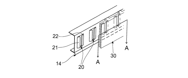
FIG. I is an isometric view of a first embodiment of the skirt
CA 02697251 2010-02-22
WO 2008/052244 PCT/AU2007/001530
4
hanger showing a section of skirt mounted thereon;
FIG. 2 is a front elevational view of the skirt hanger;
FIG. 3 is an end elevational view of the skirt hanger (with the
skirt shown in dashed lines);
FIG. 4 is a top plan view of one pair of the opposed jaws;
FIG. 5 is a sectional top plan view, taken on line A-A on FIG. 1,
showing the engagement of the skirt with opposed pairs of the jaws;
FIG. 6 is an enlarged view of the teeth on one of the jaws;
FIG. 7 is a perspective view showing the
installation/adjustment of the skirt on the skirt hanger;
FIG. 8 is an isometric view of a second embodiment of the skirt
hanger;
FIG. 9 is an end elevational view of the second embodiment;
FIG. 10 is a sectional end view of a second embodiment of the
skirt; and
FIG. 11 is a sectional top plan view of a third embodiment of
the skirt.
DETAILED DESCRIPTION OF THE
PREFERRED EMBODIMENTS
Referring to the first embodiment of FIGS. I to 7, the skirt
hanger 10 is roll-formed from a length of, eg., stainless steel or aluminium
strip into a substantially C-shape with a front wall 11 interconnecting
parallel
top and bottom walls 12, 13. The top and bottom walls 12, 13 enable the
skirt hanger 10 to be mounted on a suitable support structure spaced above,
CA 02697251 2010-02-22
WO 2008/052244 PCT/AU2007/001530
and extending parallel to, one side edge of a conveyor belt (not shown).
At regular spacings along the front wall, pairs of opposed jaws
20 are directed forwardly out of the front walls, where each jaw 21, 22 is
formed by, e.g., a rotating punch-and-die assembly, which deforms the jaws
5 21, 22 out of the plane of the front wall 20. Each jaw 21, 22 is terminated
by
downwardly-directed teeth 23, 24, as illustrated on an enlarged scale in FIG.
6.
NB: It will be noted that the teeth 23, 24 are downwardly-
directed so that the skirt (to be hereinafter described) is mounted on the
skirt
hanger 10 by relative downward movement of the bosses on the skirt to the
opposed pairs of teeth 20.
A sealing lip 14 extends downwardly and forwardly from the
junction of the front wall 11 and the bottom wall 13 to engage the adjacent
face of the skirt in the manner to be hereinafter described.
As illustrated in FIGS. 1, 3 and 5, the skirt 30 is preferably
formed of elastomeric material, e.g., fibre-reinforced rubber, with a body
portion 31 having opposed faces 32, 33.
Substantially T-shaped protrusions 34 are provided on the face
33 of the skirt body 31 at centre spacings equal to the centre spacings
between adjacent opposed pairs of jaws 20 on the skirt hanger 10. Each
boss 34 is located above, and aligned with, an adjacent opposed pair of jaws
20 and the skirt 30 is then pushed downwardly, relative to the hanger 10, to
cause each opposed pairs of jaws 20 to engage a respective T-shaped boss
34.
CA 02697251 2010-02-22
WO 2008/052244 PCT/AU2007/001530
6
As shown more cleariy in FIG. 5, each jaw 21, 22 engages an
opposite side of a respective T-shaped boss 34, where the teeth 23, 24
engage opposite sides of the "leg" 36 connecting the T-shaped boss 34 to
the skirt body 31. (The spacing between opposed teeth 23, 24 is preferably
just less, eg., 90-95% of the thickness of the "leg" 36 so that the teeth 23,
24
will "dig into" the T-shaped boss 34.) As hereinbefore described, the teeth
23, 24 are downwardly directed so that the skirt 30 can be moved
downwardly, relative to the skirt hanger 10, to compensate for any wear in
the skirt body 31 due to the movement of the conveyor belt 50 beneath the
skirt 30; while preventing the skirt 30 moving upwardly relative to the skirt
hanger 10 due to the presence of any material on the conveyor belt.
The engagement of the sealing strip 14 on the skirt hanger 10
with the adjacent face 33 of the skirt 30 prevents any material on the
conveyor belt 50 escaping through the gap between the skirt body 31 and
the front wall 11 of the skirt hanger 10.
As illustrated in FIG. 7, the bosses 34 on the skirt 30 are
aligned with respective pairs of jaws 20 and can be "tapped" downwardly with
a hammer 70 (or similar tool).
As the body 31 of the skirt 30 wears, the operator can use the
hammer 70 to move the skirt 30 downwardly relative to the skirt hanger 10,
the engagement of the opposed teeth 23, 25 with the T-shaped boss 34
preventing relative upward movement of the skirt 30.
In the second embodiment illustrated in FIGS. 8 and 9, the
substantially C-shaped skirt hanger 10 is substituted by a substantially Z-
CA 02697251 2010-02-22
WO 2008/052244 PCT/AU2007/001530
7
shaped skirt hanger 110, where the sealing strip 114 is formed integrally with
the front wall 111 and the top wall 112. The opposed pairs of jaws 120 have
their jaws 121, 122, configured as for the jaws 21, 22 of the C-shaped skirt
hanger 10.
FIG. 10 illustrates a second embodiment of the profile for the
skirt, where the skirt 130 has a very deep skirt body 131. In some
installations, supporting the skirt 130 from the hangers 10, 110 by the bosses
134 at the top of the body 130 may result in the skirt body 131 being
deflected out of contact with the conveyor belt. In this embodiment, a
second set of T-shaped bosses 135 are provided on face 132, ie., on the
opposite side of the skirt body 131. The second bosses 135 are of the same
T-shape as for bosses 134 and are provided at the same centre spacings.
However, the second bosses 135 are spaced a distance below the top edge
137 of the skirt body 131 (but preferably overiap the bosses 134 in height).
In use, the skirt 130 is initially installed on the hangers 10, 110
with the opposed pairs of teeth 20, 120 engaged with the second bosses
135. The skirt 130 is moved down until the full height of the second bosses
135 has been used; the skirt 130 is pulled downwardly to be released from
the hangers 10, 110; is then reversed, ie., to bring face 133 adjacent the
hangers 10, 110; and the bosses 134 are engaged with the opposed pairs of
jaws 20, 120 in hangers 10, 110, and adjusted for further use on the skirt
130. (in use, some or all of the second bosses 135 may be worn away when
the skirt 130 is mounted in the hangers 10, 110 by the bosses 134.)
When a skirt 30, 130 is due for renewal, it can be removed by
CA 02697251 2010-02-22
WO 2008/052244 PCT/AU2007/001530
8
pushing the bosses 34, 134, 135 downwardiy to release them from the
opposed jaws 20, 120 of the hangers 10, 110. However, it is more usual to
cut the "legs" 36, 136 of the first few bosses 34, 134, 135 adjacent one end
of the skirt 30, 130; and then pulling the end of the skirt 30, 130 outwardly
relative to the hangers 10, 110, thereby tearing the "legs" 36, 136 of the
bosses 34, 134 to release the skirt body 31, 131 from the hangers 10, 110.
In the embodiments illustrated, the skirts 30, 130 have bosses
34, 134, 135 of substantially T-shape, ie., with a "leg" 36, 136 and
"transverse head". It will be readily apparent to the skilled addressee that
the
bosses 34, 134, 135 may be substituted by protrusions 234 each having a
shank 236 interconnecting an enlarged, eg., square or round head 238, to
the adjacent skirt body 231, as illustrated in FIG. 11, showing a third
embodiment of the skirt 230.
The embodiments described provide a simple, efficient skirting
, 15 system for conveyor belts, where the hangers 10, 110 can be easily
manufactured and installed; and the skirts 30, 130 can easily be mounted on,
or be removed from, the hangers 10, 110.
Various changes and modifications may be made to the
embodiments described and illustrated without departing from the present
invention.