Note: Descriptions are shown in the official language in which they were submitted.
CA 02697845 2010-02-25
WO 2009/032860 PCT/US2008/075149
X-RAY TUBE WITH ENHANCED SMALL SPOT CATHODE AND METHODS FOR
MANUFACTURE THEREOF
TECHNICAL FIELD
[0001] The invention relates generally to x-ray tubes and, more particularly,
to x-ray
tubes having cathodes configured to produce small electron beam spots on
targets, without
producing halos surrounding these spots.
CROSS REFERENCE TO RELATED APPLICATIONS
[0002] This application claims the benefit of U.S. Provisional Patent
Application No.
60/969,926, filed September 4, 2007, titled "X-Ray Tube with Enhanced Small
Spot Cathode
and Methods for Manufacture Thereof," the entire contents of which are hereby
incorporated by
reference herein, for all purposes.
BACKGROUND ART
[00031 A typical miniature x-ray tube includes an evacuated ceramic tube with
a cathode
structure at one end of the tube and an anode structure at or near an opposite
end of the tube.
Traditionally, the cathode is heated to facilitate releasing electrons, and a
high-voltage electric
field is established between the cathode and the anode to accelerate the
released electrons
toward, and possibly beyond, the anode. There may be a short focusing element
within the tube.
If present, the focusing element includes electrically conducting material for
creating an electric
field. The focusing element is formed such that the electric field tends to
concentrate the flow of
electrons into a compact stream. The effectiveness of any focusing depends to
a significant
degree on the size of the area on the cathode from which the electrons are
emitted. The smaller
the area, the easier it is to develop a well defined small spot on the target.
[0004] The electron beam strikes a target at the far end of the ceramic tube,
resulting in
the production of x-rays. The target may be the anode or another structure.
The target usually
includes a thin, heavy metal coating, such as gold (Au) or tungsten (W), on
the surface of a
material that allows the x-rays to pass through with little attenuation. In
some cases, the x-ray
beam may be taken off of a more conventional solid, x-ray opaque target at an
angle as scattered
x-rays. In either case, the x-rays are produced from a spot on the target
where the electron beam
strikes the target.
-1-
CA 02697845 2010-02-25
WO 2009/032860 PCT/US2008/075149
[0005] To improve electron emissions from cathodes, most cathodes are now made
from
thoriated tungsten using a process described by Langmuir. In that process,
about 2% thorium
oxide is mixed with tungsten. Cathodes made of this material are then
"activated" by heating
them to about 2800 degrees Kelvin (K), which reduces any thorium oxide to a
mono layer of
metallic thorium on the surface of the tungsten. Carbon is added to the
surface to carbonize
some of the tungsten to tungsten carbide, which limits the rate of evaporation
of the thorium
from the surface. The result is a cathode that has several orders of magnitude
more emission
than pure tungsten. Other details regarding construction of prior-art
miniature x-ray tubes are
disclosed in U.S. Pat. No. 7,236,568.
[0006] In many applications, it is important that the area or a dimension of
the spot on
the target is as small as possible. However, it has been found that a
conventional x-ray tube
produces a spot of x-ray emissions surrounded by an undesirable "halo" of x-
ray emissions, as a
result of heat spreading in the cathode, as described in the following
paragraphs.
[0007] Traditionally, the cathode is either a directly heated filamentary
cathode or a
planar cathode. U.S. Pat. No. 6,320,932 discloses heating a cathode by a laser
light source. The
use of a laser heat source makes planar cathodes easier to implement. In
addition, heating a
small area in the center of a thin metal cathode gives a more intense emission
from the heated
area than from unheated areas. An electron beam spot on the order of a few
hundred microns in
diameter is achievable using a laser-heated planar cathode.
[0008] However, heat is conducted from the central, directly heated area of
the cathode
to adjacent portions of the cathode, which causes the cooler portion of the
cathode to emit
electrons, albeit at a much lower rate, such as about 1/20 to about 1/100 that
of the central,
directly heated part of the activated cathode area. This results in a "halo"
around the x-ray spot
on the target. In a miniature x-ray tube, an exemplary cathode is on the order
of 2-3 mm in
diameter, and the central electron beam is about 0.2 mm in diameter. Thus, the
area of the halo
may be approximately 100 times the area of the central spot. Such a halo forms
an undesirable
background in a measurement.
SUMMARY OF THE INVENTION
[0009] An embodiment of the present invention provides an x-ray source with an
enhanced small spot cathode. Such an x-ray source includes a housing, a
cathode disposed
within the housing and an anode spaced apart from the cathode. The cathode has
an area and a
passivation layer over only a portion of the area. The anode is adapted for a
voltage bias with
-2-
CA 02697845 2010-02-25
WO 2009/032860 PCT/US2008/075149
respect to the cathode for accelerating electrons emitted from the cathode.
The x-ray source also
includes an x-ray emitter target disposed within the housing. The x-ray
emitter target is spaced
apart from the cathode for impact by the accelerated electrons. The
passivation layer may
include a pyrolytic material, such as platinum or tantalum. The cathode may
also include a
thoriated tungsten layer. The portion of the cathode that is not covered by
the passivation layer
may be activated, such as with carbon.
[0010] Another embodiment of the present invention provides a method for
manufacturing a cathode for an x-ray source. The method includes providing a
base layer that
has an area and passivating only a portion of the area of the base layer,
thereby defining an
emission portion of the base layer.
[0011] Passivating the portion of the base layer may include applying a
pyrolytic
material, such as platinum or tantalum, to the portion of the base layer.
Providing the base layer
may include providing a thoriated tungsten layer. The method may also include
activating at
least an emission portion of the thoriated tungsten layer, such as by
activating the emission
portion with carbon.
BRIEF DESCRIPTION OF THE DRAWINGS
[0012] The invention will be more fully understood by referring to the
following
Detailed Description of Specific Embodiments in conjunction with the Drawings,
of which:
Fig. 1 is a longitudinal cross-sectional view of an x-ray tube, according to
one
embodiment of the present invention;
Fig. 2 is an end view of a cathode of the x-ray tube of Fig. 1;
Fig. 3 is an end view of a target of the x-ray tube of Fig. 1;
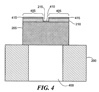
Fig. 4 is a cross-sectional view of the cathode of Fig. 2;
Fig. 5 is a flowchart describing a process for manufacturing a cathode for an
x-
ray source, according to one embodiment of the present invention; and
Fig. 6 is a chart showing emissivity of various metals as a function of
temperature, according to the prior art.
DETAILED DESCRIPTION OF SPECIFIC EMBODIMENTS
[0013] In accordance with preferred embodiments of the present invention, an x-
ray
source with an enhanced small spot cathode is disclosed, as well as methods
for manufacturing
such an x-ray source. Such an x-ray source overcomes the halo problem, and
corresponding
-3-
CA 02697845 2010-02-25
WO 2009/032860 PCT/US2008/075149
undesirable background, of prior art x-ray tubes, while retaining the high
emissivity, and well-
defined central beam, of an activated thoriated tungsten cathode with a small
activated area.
[0014] As noted, in many applications, it is important that the area or a
dimension of the
x-ray spot of an x-ray source is as small as possible. The size of the x-ray
spot on the target
depends largely on the size of the area from which electrons are emitted from
the cathode and
any focusing or dispersion that takes place as the electrons transit to the
target. In the case of
miniature x-ray tubes, such as x-ray tubes produced by North Star Imaging,
Inc., Rogers, MN,
Moxtek, Inc. Orem, UT and twX, LLC, West Concord, MA, the electric field
structure is such
that the electron beam spreads very little in transit to the target. The
electron beam spot on the
target is, therefore, a relatively faithful image of the cathode emission
area, with a very slight
size change.
[0015] Fig. 1 is a longitudinal cross-sectional schematic diagram of an x-ray
tube 100,
according to one embodiment of the present invention. The x-ray tube includes
a ceramic tube
105, a thoriated tungsten cathode 110 and a target 115. The cathode 110 and an
anode on the
target 115 are connected to an appropriate high-voltage power supply (not
shown). The cathode
110 may be heated via an optical fiber 120 coupled to a laser heat source (not
shown), by a
filament (not shown) or by another structure. The x-ray tube 100 may include a
focusing system
125. An electron beam 130 emitted from the cathode 110 strikes the target 115
to produce x-rays
135.
[0016] Fig. 3 is an end view (as viewed from within the ceramic tube 105)
schematic
diagram of the target 115 of the x-ray tube of Fig. 1. The target 115 includes
a metal support 300
vacuum sealed to the ceramic tube 105. To the target 115 is attached an anode
305, typically
made of gold (Au) or tungsten (W) coated on a sufficiently x-ray transparent
material. In
operation, the electron beam 130 (Fig. 1) strikes the target 115 to create an
image spot 310 of the
cathode 110.
[0017] Fig. 2 is an end view (as viewed from within the ceramic tube 105)
schematic
diagram of the cathode 110, and Fig. 4 is a cross-sectional schematic diagram
of the cathode
110. The cathode 110 includes a metal support 200 vacuum sealed to the ceramic
tube 105. An
apx. 100 m thick, apx. 2-3 mm diameter, thoriated tungsten disk 205 is
attached to the center of
the support 200. The disk 205 is made of thoriated tungsten and is supported
so that the disk 205
may be heated. The metal support 200 defmes an aperture 400 (Fig. 4), in which
the optical the
optical fiber 120 (not shown) may terminate.
[0018] In the illustrated embodiment, the cathode 110 is passivated by an apx.
10-30 m
thick layer 210 of pyrolytic material, such as platinum or tantalum, except
for a small (apx.
-4-
CA 02697845 2010-02-25
WO 2009/032860 PCT/US2008/075149
150 m diameter) area 215, from which desired emissions take place.
Considerations for
selecting an appropriate passivation material are discussed below. The
emission area 215 is
activated, as discussed below, and may be circular or any other desired shape.
The passivation
210 eliminates or substantially reduces the halo effect described above, while
precisely defining
the area 215 of emission.
[0019] Platinum and tantalum are well-suited passivators, because both
materials have
work functions greater than that of thoriated tungsten. Platinum has a work
function of
approximately 6.3 eV, and tantalum has a work function of approximately 4.1
eV, whereas
thoriated tungsten has a work function of approximately 2.6 eV. Thus,
emissions from the
platinum-passivated or tantalum-passivated area 405 are several orders of
magnitude less than
emissions from the activated thoriated tungsten portion 215. The emissivity of
various material
can be estimated using the Richardson-Dushman equation (1):
I = AT2e-ba/T (1)
where:
I= current in amperes per cm2;
A= constant determined by the material;
T= temperature in degrees Kelvin (K); and
bo = 11,600 x (work function).
[0020] The passivation material 210 may be selectively deposited on the
thoriated
tungsten disk 205 using any appropriate technique, such as vacuum deposition
using a small
mask in the area 215 of the emission portion of the cathode 110, masking and
electrodeposition,
or a technique used in micro-electro-mechanical systems (MEMS) fabrication.
[0021] Once the disk 205 is fabricated with the passivated area 210, the
emission
portion 215 of the cathode 110 may be activated using any appropriate
technique, such as
depositing carbon on the emission portion 215 of the cathode 110, yielding an
activation layer
410. Most activation techniques cause carbon 415 to also be deposited on top
of the passivation
layer 210. However, platinum and tantalum are not activated by carbon. Thus,
the platinum or
tantalum passivation layer 210 serves as a passivator and prevents a halo,
even if the platinum or
tantalum is coated with carbon 415.
[0022] Fig. 5 is a flowchart of a process for manufacturing a cathode for an x-
ray
source, according to one embodiment of the present invention. At 500, a base
layer of thoriated
tungsten is provided. The thoriated tungsten base layer may be a circular disc
or another shape.
The thoriated base layer may be attached to, or otherwise supported by, a
metal or other suitable
-5-
CA 02697845 2010-02-25
WO 2009/032860 PCT/US2008/075149
support. At 502, a portion of the base layer is passivated, such as by
applying a layer of
platinum, tantalum or other pyrolytic material to the portion of the base
layer. An unpassivated
portion, i.e. an emission portion, of the base layer is defined by the
passivation layer. The
emission portion may be circular or another shape. At 504, the emission
portion of the thoriated
tungsten is activated by applying carbon or another suitable material to the
thoriated tungsten.
[0023] Fig. 6 is a graph showing emissivity of various metals as a function of
temperature. As shown in the chart, the emissivity of platinum or tantalum is
several orders of
magnitude less than that of thoriated tungsten, at normal operating
temperatures of about 1,800-
2,200 K. Other suitable passivating materials (including materials not listed
in the graph of Fig.
6) may be chosen, depending on the degree of passivation required.
[0024] Temperature-related factors may be considered when choosing a
passivation
material. For example, while platinum has a higher work function than tantalum
(and, therefore,
is a more effective passivator), platinum has a lower melting temperature
(about 1,770 C) than
tantalum. Furthermore, tantalum forms a carbide at temperatures normally used
to activate
thoriated tungsten. The tantalum carbide offers protection for the tantalum
and has a melting
temperature above about 3,800 C.
[0025] A cathode with a passivated area has at least two desirable features.
First, such a
cathode has a well-defined emission area. The remainder of the cathode area is
passivated; thus,
for all intents and purposes, no, or significantly less, thermionic emissions
take place from the
passivated area. Second, a surface that is covered with platinum or tantalum
is more resistant to
damage from ion bombardment.
[0026] A miniature x-ray tube typically requires only about 10-100
microamperes of
current. The small emission portion of the cathode, i.e., the activated
tungsten portion, is large
enough to provide the required current. For example, the graph in Fig. 6 shows
that, at about
1,800 K, a cathode is capable of giving off about 0.5 amperes per square
centimeter. In the
example x-ray tube discussed above, with respect to Figs. 1-4, a 150 m
diameter emitting area
is capable of providing about 8 microamperes.
[0027] While the invention is described through the above-described exemplary
embodiments, it will be understood by those of ordinary skill in the art that
modifications to, and
variations of, the illustrated embodiments may be made without departing from
the inventive
concepts disclosed herein. For example, although a tubular x-ray source is
described, a spherical
or other shaped housing may be used, depending on an intended use of the x-ray
source.
Moreover, disclosed aspects, or portions of these aspects, may be combined in
ways not listed
-6-
CA 02697845 2010-02-25
WO 2009/032860 PCT/US2008/075149
above. Accordingly, the invention should not be viewed as being limited to the
exemplary
embodiments.
-7-