Note: Descriptions are shown in the official language in which they were submitted.
SYSTEM AND METHOD FOR DYNAMICALLY MAINTAINING THE STABILITY OF A
MATERIAL HANDLING VEHICLE HAVING A VERTICAL LIFT
CROSS-REFERENCE TO RELATED APPLICATIONS
[001] N/A
BACKGROUND OF THE INVENTION
[002] The present invention relates to the field of industrial trucks and, in
particular, to a
dynamic stability control system for a material handling vehicle having a
lifting fork.
[003] One method for improving material handling vehicle stability includes
performing a
static center-of-gravity (CG) analysis while the vehicle is at rest and
limiting vehicle operating
parameters (for example, maximum speed and steering angle) accordingly.
However, this static
calibration does not dynamically account for vehicle motion, changing lift
heights, or
environmental factors such as the grade of a driving surface.
[004] Other methods for improving vehicle stability common in consumer
automobiles include
calculating vehicle CG during vehicle movement and employing an anti-lock
braking system
(ABS) to modify the cornering ability of the vehicle. These prior art methods
only consider two-
dimensional vehicle movement (forward-reverse and turning) and do not, for
example, account
for three-dimensional CG changes due to load weights being lifted and lowered
while a vehicle
is in motion.
[005] It would therefore be desirable to have a method for dynamically
maintaining the
stability of a material handling vehicle that accounts for vehicle motion and
complex CG
changes imposed by a load weight.
SUMMARY OF THE INVENTION
[005A] According to a broad aspect of the invention, there is provided a
method of maintaining a
dynamic stability of a material handling vehicle having a vertical lift, the
method comprising:
a) continuously calculating dynamic center-of-gravity parameters for the
vehicle over a time
interval during which the vehicle is moving, wherein a vertical position of
the dynamic center-
of-gravity is dependent on a position of the vertical lift; b) continuously
calculating wheel loads
based on the calculated dynamic center-of-gravity parameters; and c) adjusting
vehicle
operating parameters based on the calculated wheel loads and calculated
dynamic center-of-
gravity parameters to maintain vehicle dynamic stability.
- 1 -
CA 2698056 2017-06-19
[006] The present invention according to its embodiments seeks to overcome the
drawbacks of
previous methods by providing a system and method for improving the dynamic
stability of a
material handling vehicle that is able to dynamically assess vehicle stability
and adjust vehicle
operation in response. The method includes analyzing dynamic vehicle
properties such as
velocity, travel direction, acceleration, floor grade, load weight, lift
position and predicting
wheel loads and three-dimensional center-of-gravity positions.
[007] The present invention according to its embodiments provides a method of
maintaining
the dynamic stability of a material handling vehicle having a vertical lift.
The method includes
continuously calculating dynamic center-of-gravity parameters for the vehicle
over a time
interval during which the
- la -
CA 2698056 2017-06-19
vehicle is moving, wherein a vertical position of the dynamic center-of-
gravity is strongly
dependent on a position of the vertical lift. The method further includes
continuously calculating
wheel loads based on the calculated dynamic center-of-gravity parameters and
adjusting vehicle
operating parameters based on calculated and predicted wheel loads and center-
of-gravity
parameters to maintain vehicle dynamic stability.
[008] The present invention according to its embodiments also provides a
material handling
vehicle including a motorized vertical lift, traction motor, steerable wheel,
steering control
mechanism, and brake. The material handling vehicle further includes a
stability control system
having a plurality of sensors configured to measure dynamic vehicle
properties, a sensor input
processing circuit, a vehicle memory configured to store static vehicle
properties. The control
system further includes a stability computer, vehicle control computer, and a
plurality of vehicle
function controllers configured to maintain vehicle dynamic stability in
accordance with the
above-mentioned method.
[009] Various other features of the present invention will be made apparent
from the following
detailed description and the drawings.
BRIEF DESCRIPTION OF THE DRAWINGS
[0010] Fig. 1 is a perspective view of a lift truck employing a stability
control system in
accordance with embodiments of the present invention;
[0011] Fig. 2 is a schematic view of a control system for maintaining the
dynamic stability of a
material handling vehicle in accordance with embodiments of the present
invention;
[0012] Fig. 3 is a flowchart setting forth the steps for assessing and
maintaining the dynamic
stability of a material handling vehicle in accordance with embodiments of the
present invention;
[0013] Figs. 4A - 4C are alternate views of a free-body diagram for a three-
wheeled material
handling vehicle that may be employed to calculate vehicle center-of-gravity
and wheel loads in
accordance with embodiments of the present invention; and
[0014] Fig. 5 is a schematic showing vehicle stability in relation to center-
of-gravity position in
accordance with embodiments of the present invention.
DETAILED DESCRIPTION OF THE INVENTION
[0015] The present invention according to its embodiments provides a system
and method for
maintaining the dynamic stability of a material handling vehicle having a
vertical lift. Generally,
the vehicle's wheel loads and dynamic CG parameters are calculated over a time
period during
which the vehicle is
- 2 -
CA 2698056 2017-06-19
CA 02698056 2010-03-26
moving and the vehicles operating parameters are adjusted based on the
calculated wheel loads
and CG parameters, as well as predicted wheel load and CG parameters.
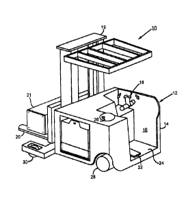
[0016] Referring now to the Figures, and more particularly to Fig. 1, one
embodiment of a
material handling vehicle or lift truck 10 which incorporates the present
invention is shown. The
material handling vehicle 10 includes an operator compartment 12 comprising a
body 14 with an
opening 16 for entry and exit of the operator. The compartment 12 includes a
control handle 18
mounted to the body 14 at the front of the operator compartment 12 proximate
the vertical lift 19
and forks 20 carrying a load 21. The lift truck 10 further includes a floor
switch 22 positioned on
the floor 24 of the compartment 12. A steering wheel 26 is also provided in
the compartment 12
disposed above the turning wheel 28 it controls. The lift truck 10 includes
two load wheels 30
proximate to the fork 20 and vertical lift 21. Although the material handling
vehicle 10 as shown
by way of example as a standing, fore-aft stance operator configuration lift
truck, it will be
apparent to those of skill in the art that the present invention is not
limited to vehicles of this
type, and can also be provided in various other types of material handling and
lift vehicle
configurations. For brevity and simplicity, material handling vehicles are
hereinafter referred to
simply as "vehicles" and "loaded vehicles" when carrying a load weight.
[0017] Referring now to Fig. 2, one embodiment of a control system 34
configured to maintain
vehicle dynamic stability in accordance with the present invention is shown.
The control system
34 includes an array of sensors 36 linked to a sensor input processing circuit
38, which are
together configured to acquire and process signals describing dynamic vehicle
properties such as
speed, direction, steering angle, floor grade, tilt, load weight, lift
position, and sideshift. For
example, the sensor array 36 may employ a motor controller, tachometer, or
encoder to measure
vehicle speed; a potentiometer or feedback from a steering control circuit to
measure steering
angle; a load cell, hydraulic pressure transducer, or strain gauge to measure
load weight; an
encoder to measure lift height; or three-axis accelerometers to measure tilt,
sideshift, reach, and
floor grade. The sensor input processing circuit 38 is linked to a vehicle
computer system 40 that
includes a stability CPU 42, vehicle memory 44, and vehicle control computer
46, which
together analyze static vehicle properties and dynamic vehicle properties to
assess vehicle
stability. Changes to vehicle operating parameters based on the assessed
vehicle stability are
communicated from the vehicle control computer 46 to function controllers 48,
which adjust the
operation of vehicle actuators, motors, and display systems 50 to maintain
vehicle stability. For
example, adjusted vehicle operating parameters may be received by a lift
function controller 52
that activates a motor 54 to change lift position; a travel function
controller 56 to relay maximum
- 3 -
CA 02698056 2010-03-26
speed limitations to a vehicle motor 58; a display controller 60 and display
62 to communicate
present or pending changes in vehicle operating parameters to a driver; and a
steering function
controller 68 that directs a steering motor 70 to limit steering angle. The
vehicle control
computer may also include a braking function controller 64 and brake 66 to
adjust vehicle speed.
[0018] Referring to Fig. 3, the above lift truck 10 and control system 34 may
be employed to
maintain vehicle dynamic stability. A method for maintaining dynamic vehicle
stability starts at
process block 100 with the input of vehicle data to the vehicle computer
system 40. Vehicle data,
which is retrieved from the vehicle memory 44, may include static vehicle
properties such as
unloaded vehicle weight and CG, wheelbase length, and wheel width and
configuration. At
process blocks 102 and 104 respectively load weight and carriage height are
input from the
sensor array 36 and sensor input processing circuit 38 to the computer system
40. A residual
capacity is then calculated at process block 106 to determine if vehicle
capacity, for example,
vehicle position and load weight, is within acceptable bounds. If, at decision
block 108, it is
decided that vehicle capacity is exceeded, then the driver is notified at
process block 110 and
vehicle operation may be limited at process block 111. If vehicle capacity is
within the
acceptable bounds, then carriage position and vehicle incline angle are input
at process blocks
112 and 114 respectively.
[0019] Referring now to Figs. 3 and 4, loaded vehicle CG is calculated at
process block 116 by
the stability CPU 42 based on static vehicle properties input at process block
100 and the
dynamic vehicle properties such as those input at process blocks 102, 104,
112, and 114. For
example, the free-body diagram (FBD) shown in Fig. 4 shows the position of the
CG, indicated
by XcG3 YCG, and ZCG, in relation to the turning wheel and load wheels of a
three-wheel material
handling vehicle and the loaded weight W at the CG. It should be noted that
YcG is strongly
dependent on load weight and lift position and that heavy load weights at
increasing lift heights
elevate the CO and reduce vehicle stability. If, at decision block 118, the
vehicle is deemed
stable, then vehicle speed is input at process block 120 and vehicle movement
is assessed at
decision block 122. If the vehicle is moving, then the steering angle is input
at process block 124
and operator commands are input at process block 126.
[0020] At process block 128, the effects of vehicle movement on wheel loading
are calculated.
For example, wheel loads for a three-wheeled vehicle can be calculated by
again considering the
FBD of Fig. 4, which describes the distance A from the vehicle centerline CL
to the turning
wheel 28, the distance B from the CL to the load wheels 30, and the distance L
between the
turning wheel 28 and the axis-of-rotation of the load wheels 30. From these
distances and the
- 4 -
CA 02698056 2010-03-26
steering angle 0 input at process block 124, a heading angle a and turning
radius r are calculated
using the following equations:
L ¨ XCG
a = A tan
Eqn. 1;
___________________________________________ B + A
tan
and
L - XCG
r=
sin a Eqn.
2.
[0021] Normal and tangential accelerations, at and a. respectively, are then
calculated using
the following equations:
¨ vo
=
Eqn. 3;
and
V2
= ¨
Eqn. 4;
[0022] where v is current vehicle velocity, vo is the last measured vehicle
velocity, t is the time
between velocity measurements. It is then possible, using these values and by
analyzing the FBD
of Fig. 3, to produce the following equations describing wheel load:
W (L ¨ X cG) cos(7F )¨ WYCG sin(7F) WYCG 386.4 (a, cos(a) ¨ a n sin(a))
ND = Eqn.
5;
W (B ¨ Z c) cos(yL ) ¨ WYcG sin(yL )+ WYcc(a cos(a) ¨ a, sin(a))
NLI = 386.4 Eqn.
6;
2B
and
- 5 -
=
NL2 = W cos(a ) cos(aF)- ND - NLI
Eqn. 7;
[0023] where YL is the lateral ground angle and 7F is the fore/aft ground
angle as determined at
process block 114. In this case, ND is the load at the turning wheel, Nu is
the load at the left load
wheel, and NL2 is the load at the right load wheel.
[0024] Referring to Fig. 3, at decision block 130 it is decided if the wheel
loads are acceptable.
If unacceptable, for example, a wheel load approaching zero or another
predetermined threshold,
then the system notifies the operator at process block 110 and adjusts vehicle
operation at
process block 111 to maintain vehicle stability. For example, the computer
system 40 may adjust
vehicle operation by limiting or reducing the vehicle speed and communicate
these changes to
the operator via the display controller 60 and display 62. Illustratively, the
present invention
according to its embodiments is intended to further improve vehicle dynamic
stability by
allowing future CG parameters and wheel loads to be predicted based on trends
in the measured
dynamic vehicle properties and for vehicle operating parameters to be adjusted
accordingly.
[0025] Referring to Figs. 3 and 5, at process block 102 the CG position
determined at process
block 84 is compared to a range of stable CG positions. It is contemplated
that this may be
performed by locating the CG position 200 within a stability map 202 relating
a range of
potential CG positions to vehicle stability. It should be noted that the
stability map 202 is for a
four-wheeled material handling vehicles having two turning wheels 28 and two
load wheels 30.
The stability map 202 may include a preferred region 204, limited region 206,
and undesirable
region 208 whose sizes are dependent on system operating parameters. For
example, applications
requiring a high top speed may employ more stringent vehicle stability
requirements and thus
reduce the size of the preferred region 204. At process block 134, trends in
measured dynamic
vehicle properties, CG parameters, and wheel loads are analyzed to predict
future vehicle
stability. This may be achieved, for example, by analyzing trends in CG
position 200 to
determine its likelihood of entering the limited region 206 or by analyzing
wheel loading trends
to ensure that they remain within stable bounds. To adequately model future
vehicle stability it is
contemplated that the CG parameters and wheel loads are calculated
approximately ten times per
second.
[0026] At process block 136, vehicle operation rules are input to the computer
system and, at
process block 138, parameters relating to future vehicle stability, for
example, predicted wheel
loads or CG position, are compared to the vehicle operation rules to determine
if vehicle
operating parameters should be adjusted in response. If, at decision block
140, it is decided that
- 6 -
CA 2698056 2017-06-19
vehicle operating parameters should be adjusted, then the driver is notified
at process block 110
and the control system specifies an appropriate change in vehicle operating
parameters to
maintain vehicle stability at process block 111. For example, if a wheel load
falls below a
minimum threshold specified by the vehicle operation rules, then vehicle speed
may be limited to
prevent further reduction in wheel load and the accompanying reduction in
vehicle stability. It is
contemplated that vehicle dynamic stability may also be improved in such an
event by limiting
steering angle, lift height, or vehicle speed.
[0027] In addition to the calculated CG parameters and wheel loads, potential
force vectors
projected by the vehicle may also be analyzed to maintain vehicle dynamic
stability. An
accelerating vehicle projects a force approximately equaling the mass of the
vehicle (including a
load) times vehicle acceleration. This force vector, which is centered at the
CG and projected in
the direction of travel, is typically counteracted by the weight of the
vehicle. However, if the
projected force vector exceeds the vehicle weight, then the vehicle parameters
may require
modification. Therefore, the present invention according to its embodiments
may analyze trends
in the projected force vector and adjust vehicle operation if the force vector
exceeds a threshold
specified by the vehicle operation rules.
[0028] The present invention according to its embodiments provides another
method for
maintaining vehicle dynamic stability. Possible low-stability scenarios such
as a sudden change
in vehicle speed or direction can be modeled and vehicle CG, wheel loads, and
force vectors can
be predicted in the event of such a scenario. If the modeled CG parameters,
wheel loads, and
force vectors fall outside a preferred range, then vehicle operation
parameters may be adjusted to
improve vehicle stability during the potential low-stability scenario.
[0029] The present invention has been described in accordance with the
embodiments shown,
and one of ordinary skill in the art will readily recognize that there could
be variations to the
embodiments, and any variations would be within the scope of the present
invention. It is
contemplated that addition sensors and vehicle properties could be employed to
further improve
vehicle stability. Conversely, vehicle properties and the associate hardware
used to measure and
process them may be excluded from the present invention to reduce system costs
and
complexity. Accordingly, many modifications may be made by one of ordinary
skill in the art
without departing from the scope of the appended claims.
- 7 -
CA 2698056 2017-06-19