Note: Descriptions are shown in the official language in which they were submitted.
CA 02698176 2010-03-30
ENERGY RECUPERATING FILTRATION APPARATUS
FIELD OF THE APPLICATION
The present application relates to a filtration
apparatus of the type used in processes and systems in which
bulk materials are transformed into a smaller uniform
format, such as granules, pellets, or the like.
BACKGROUND OF THE ART
It is commonly known to process bulky materials to
convert these to a given format. For example, in the
animal-feed industry, the feed is often produced as a mass
of raw material, and must be converted to a suitable
particle format (granules, balls, pellets, among many other
possibilities) to be edible by animals. As another example,
in the production of fuel from biomass, it is desired to
produce pellets as pellets are well suited for efficient
combustion.
Accordingly, various systems and processes are
commonly used for such transformation. However, such
systems and processes may always be improved in terms of
energy efficiency, whereas waste resulting from the
transformation must be minimized.
SUMMARY OF THE APPLICATION
It is therefore an aim of the present disclosure
to provide a novel filtration apparatus.
Therefore, in accordance with the present
application, : there is provided a filtration apparatus for
filtering solid particles from a gas, with capturing solids,
comprising: a casing defining an inner cavity with an upper
cylindrical portion, and a lower hopper portion connected to
the upper cylindrical portion; at least one inlet in the
upper cylindrical portion for feeding a flow of gas and
solids into the inner cavity, the at least one inlet being
positioned with respect to the casing to cause movement of
CA 02698176 2010-03-30
-2-
the solids in a downward spiral path in the casing; a solids
outlet at a bottom of the lower hopper portion for
outletting the solids from the casing; a gas outlet in the
upper cylindrical portion to exhaust gases from the casing;
an annular arrangement of ports in a wall of the lower
hopper portion of the casing to inject an other gas into the
inner cavity, the ports being oriented so as to guide the
other gas into following a path at least partially vertical
when entering the inner cavity to disrupt the movement of
the solids in the downward spiral path to allow a capture of
the solid particles by the capturing solids; and a gas
source connected to the arrangement of ports for the
injection of the other gas into the inner cavity.
Further in accordance with the present applica-
tion, there is provided a method for filtering solid
particles from exhaust air in a process of the type in which
raw material is transformed into elements of predetermined
shape, the process using drying air to remove at least one
of moisture and heat from the mass of raw material, with air
exhausted from the process having solid particles of the raw
material in suspension, comprising: supplying a flow of the
exhaust air having solid particles of the raw material in
suspension, and parts of the raw material to a filtration
apparatus; inducing a mixing of the exhaust air and of the
raw material in the filtering apparatus for the raw material
to capture solid particles; outletting the raw material with
captured solid particles from the filtering apparatus; and
outletting the exhaust air without the captured solid
particles separately from the raw material.
BRIEF DESCRIPTION OF DRAWINGS
Fig. 1 is a perspective view of a system using a
filtration apparatus in accordance with the present
disclosure;
Fig. 2 is a schematic sectional view of the
filtration apparatus used in the system of Fig. 1; and
CA 02698176 2010-03-30
-3-
Fig. 3 is a perspective view of a sustentation
ring of the filtration apparatus of Fig. I.
DESCRIPTION OF PREFERRED EMBODIMENTS
Referring to the drawings and more particularly to
Fig. 1, there is illustrated a gas filtration apparatus 10
in accordance with the present disclosure. The filtration
apparatus 10 is illustrated in any appropriate system or
process requiring the separation of a solid from a gas, such
as a feed-producing system A of Fig. 1. Among numerous
possibilities, the filtration apparatus 10 may be used to
recuperate energy from a gas or from a solid, to allow a
reaction between a solid and solids in suspension in the
gas, to allow the absorption of moisture by the solids. The
possibilities will be related to the process with which the
filtration apparatus 10 is used.
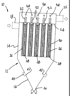
Referring to Fig. 2, the filtration apparatus 10
is shown in greater detail. The filtration apparatus 10 has
a casing 12 defining an inner cavity in which the filtration
process takes place. The casing 12 has an upper cylindrical
portion 14, and a lower hopper portion 16. The lower hopper
portion 16 has an inverted conical shape, whereby the casing
12 has a circular section (or arcuate) along its vertical
axis. An elliptical section may also be considered for the
casing 12.
An inlet 18 merges into a wall of the cylindrical
portion 14 so as to be in fluid communication with the inner
cavity of the casing 12. The inlet 18 may be tangentially
oriented with respect to the cylindrical portion 14, as it
is desired to create a cyclonic flow in the inner cavity of
the casing 12. Although a single inlet 18 is illustrated in
Fig. 2, the casing 12 may have two or more inlets, for
instance in accordance with the process or system using the
filtration apparatus 10. The inlet 18 is preferably
provided in the upper half of the cylindrical portion 14 of
the casing 12.
CA 02698176 2010-03-30
-4-
A solids outlet 20 is provided at a bottom end of
the hopper portion 16, for instance at the tip of the
inverted conical shape, and is thus in fluid communication
with the inner cavity of the casing 12. Solids therefore
exit the casing 12 via the solids outlet 20 by the effect of
gravity. A valve may close the solids outlet 20 to maintain
a given pressure or flow conditions in the inner cavity of
the casing 12. For instance, the valve 21 is a rotary
valve.
A gas outlet 22 is provided in the top of the
cylindrical portion 14, and is also in fluid communication
with the inner cavity of the casing 12. The gas outlet 22
may be connected to a side wall of the cylindrical portion
14, or to the top wall of the cylindrical portion 14.
Filtrated gas therefore exits the casing 12 through the gas
outlet 22.
The inner cavity of the casing 12 is divided into
two compartments by a support wall 24. The support wall 24
supports filters, whereby the unfiltered gas and solids
circulate in the compartment below the support wall 24,
whereas the filtered gas circulates in the compartment above
the support wall 24 to exit the casing 12.
In Fig. 2, the support wall 24 has throughbores,
with cages 26 hanging from each throughbore. The cages 26
therefore extend into the lower compartment of the casing
12, although they could also be arranged to extend in the
upper compartment of the casing 12.
Filtering membranes 28 are retained by the cages
26, and are selected to filter out given sizes of solid
particles. The filtering membranes 28 cover any free space
in the cages 26 to prevent solids from exiting the casing 12
through the gas outlet 22. According to an embodiment, the
filtering membranes 28 are sleeves slipped onto the cages
26. For instance, the membranes 28 are made of a polyester,
although any other suitable material may be used. Any other
type of filtering member may be used as an alternative to
the filtering membranes 28. For instance, it is considered
CA 02698176 2010-03-30
-5-
to position a circular filtering mesh or screen directly in
each throughbore of the support wall 24.
A protection skirt 30 projects downwardly from the
support wall 24 and encompasses the cages 26 and filtering
membranes 28. According to an embodiment, the skirt 30 has
a circular section, whereby the wall of the cylindrical
portion 14 and the protection skirt concurrently form an
annular plenum. The annular plenum may enhance the cyclonic
flow of gas in the inner cavity of the casing 12, as
described hereinafter.
Still referring to Fig. 2, nozzles 32 may be
provided in the throughbores of the support wall 24. The
nozzles 32 are of the Venturi type and increase the velocity
of a blowback flow into the filtering membranes 28. The
blowback flow is produced by jets 34. The jets 34 are
connected to a pressure source (e.g., compressed air
network, a compressor, etc.), and oriented to outlet a flow
of compressed air toward the nozzles 32. The blowback flow
may be periodically performed. Alternatively, a pressure
differential may be measured on opposed sides of the
filtering membranes 28, with the blowback being
automatically performed if the pressure differential is
above a given threshold value.
Referring to Figs. 2 and 3, a sustentation ring 40
is provided about the wall of the casing 12 at the level of
the hopper portion 16. The sustentation ring 40 is
positioned on the wall of the hopper portion 16 to blow air
into the inner cavity of the casing 12. In an embodiment,
the sustentation ring 40 is approximately located midway
along a vertical axis of the hopper portion 16. However,
the sustentation ring 40 may be located at other heights
along the vertical axis, notably about the midway line.
Accordingly, the sustentation ring 40 is in fluid
communication with the inner cavity through a plurality of
relatively small ports 42.
The ports 42 are arranged in a ring in the wall of
the casing 12, and therefore inject a gas (e.g., air) into
CA 02698176 2010-03-30
-6-
the inner cavity, with an upward vector component.
Accordingly, the solids blown along a downward cyclonic path
in the inner cavity of the casing 12 will be lifted by the
gas injected by the sustentation ring 40. A pressure source
(not shown), such as a blower, fan or compressor, is in
fluid communication with an inlet 44 of the sustentation
ring 40. The pressure of air injected by the ports 42 may
be controlled by adjusting the level of actuation of the
pressure source. By controlling the pressure of air
injected by the ports 42, a residence time of the solids in
the inner cavity of the casing 12 may be increased or
decreased.
In an embodiment, the ports 42 are sized (e.g.,
between 0.25 and 0.375 in for an inner diameter between 16
and 18 in for the ring 40) to inject gas at a flow rate of
about 2 CFM per port, with a velocity ranging between 3500
and 4000 FPM. There are a plurality of ports 42 (e.g.,
between 40 and 60 ports), spread over the full circumference
of the hopper portion 16.
Now that various components of the filtration
apparatus 10 have been described, a reaction taking place in
the filtration apparatus 10 is described.
Solids and gases to be separated are fed to the
casing 12 via the inlet 18, or inlets 18. In an embodiment,
the solids and liquid are mixed in a same pipe upstream of
the inlet 18, and hence enter the inner cavity of the casing
12 concurrently. Typically, the solids are in a granular or
aggregate form, whereas the gases may be filled with solid
particles in suspension. Moreover, the solids and gases may
be a different temperatures, and may have different levels
of humidity/moisture content.
The solids and gases enter the inner cavity of the
casing 12, and follow a downward cyclonic path. More
specifically, the inlet of gases 18 is oriented with respect
to the casing 12 so as to create a circular flow of the gas
into the inner cavity. Because of the effect of gravity,
CA 02698176 2010-03-30
-7-
the solids conveyed by the gas will move in a spiral toward
the solids outlet 20, i.e., along a downward cyclonic path.
Upon reaching the height of the ports 42, the gas
injected by the sustentation ring 40 will lift the solids,
increasing their residence time in the casing 12. According
to some embodiments, it may be desired to increase the
residence time of the solids. For instance, the increased
residence time may result in a temperature or moisture-
content adjustment for the solids. If the gas is hotter or
more humid than the solids, the solids may be heated, or may
absorb humidity from the gas. Moreover, there may be some
reaction between the solids and solid particles in
suspension in the gas. Accordingly, an increased residence
time may increase the level of solid particles captured by
the solids. Accordingly, the raw material is a capturing
solid that captures the solid particles from the gas.
The solids then reach the solids outlet 20, while
the gas follows a straight cyclonic upward path toward the
filtering membranes 28. Solid particles remaining in the
gas are filtered out of the gas by the filtering membranes
28, whereby the gas exits the lower compartment of the
casing 12 with a filtered level of solid particles.
The filtration apparatus 10 is readily cleaned.
More specifically, as the inner cavity of the filtration
apparatus 10 has very few edges, corners, cavities and
components, the use of a pressurized fluid may be sufficient
to remove unwanted particles from the surfaces of the inner
cavity.
Referring to Fig. 1, the filtering apparatus 10
may be used in any applicable systems/processes, such as
thermo-transformation, roasting, feed production, biomass
production, etc., in which a raw material (e.g., in a bulky,
chunky state) is transformed into smaller elements of a
generally uniform shape. The system A of Fig. 1 is equipped
to perform a feed production. Feed must be in the form of
pellets within a predetermined size range. The system A is
CA 02698176 2010-03-30
-8-
used to convert feed from a bulk chunk state to pellets,
having a predetermined moisture content and temperature.
A bulk feed hopper 50 outlets the feed in the bulk
chunk state into an air conveyor 52. The air conveyor 52
is, for instance, a pipe in which a gas flows, thereby
entraining the feed from the hopper 50. Although not shown,
an appropriate valve (e.g., rotary valve) may be provided at
the outlet of the hopper 50 to control the amount of feed
entering the air conveyor 52. A rotary valve may, for
instance, separate the outlet into small batches of bulk
feed.
The air conveyor 52 is in fluid communication with
the inlet 18 of the filtration apparatus 10. The treatment
of the gas and feed in the filtration apparatus 10 will be
described hereinafter. The feed exits the filtration
apparatus 10 via the solids outlet 20 of the casing 12 with
an increased temperature and/or moisture content, and thus
in a softened state.
The feed is then directed to an extruder unit 54
that converts the bulky feed to pellets. To direct the feed
from the filtering apparatus 10 to the extruder unit 54,
another air conveyor 56 is used in conjunction with an
extruder hopper 58. The air conveyor 56 may have its own
blower, or may use residual pressure flow from the
filtration apparatus 10.
The extruder unit 54 receives the feed from the
hopper 58, via inlet 60, in the softened state. Steam may
be injected into the feed to further soften it with a view
to being transformed. The extruder unit 54 may for instance
be a B1issTM unit, or any appropriate shaping unit that
converts bulky feed into an appropriate format. The
extruder unit 54 has an endless screw portion 62 pressing
the feed against an extrusion disc (not shown).
Accordingly, the feed pressed against the extrusion disc
will be converted to pellets by passing through holes in the
extrusion disc.
CA 02698176 2010-03-30
-9-
A drying unit 64 receives the feed pellets from
the extruder unit 54. The feed pellets are in the softened
state, and thus have relatively high moisture content and/or
temperature. In the drying unit 64, the feed pellets are
therefore dried, and cooled if necessary. Any appropriate
drying unit may be used. For instance, a Law-MarotT"' drying
unit (e.g., MilproT`") may be used.
The drying unit 64 typically uses a flow of air to
dry the feed pellets. The drying unit 64 may be of the type
having a reciprocating sieve into which air is blown against
a descending mass of feed pellets. Alternatively, the
drying unit 64 may feature a mesh conveyer or the like, also
allowing air to be blown against the feed pellets.
Therefore, once the feed pellets are dried, they exit the
system A, for instance via outlet conveyor 66.
The air exiting the drying unit 64, namely the
exhaust air, is humid and warm, as it has contacted the feed
pellets to dry and cool them. Moreover, the air typically
has a non-negligible level of solid particles in suspension.
Accordingly, the drying unit 64 is connected to the
filtration apparatus 10 by the air conveyor 52. This will
allow the exhaust air to be used as conveying gas for the
air conveyor 52 to convey the bulky feed from the bulk feed
hopper 50.
The filtration apparatus 10 allows the bulk feed
to be preheated by the exhaust air. Moreover, the bulk feed
is usually drier than the exhaust air, whereby the bulk feed
absorbs humidity from the exhaust air. The preheating and
moisturizing of the bulk feed will soften the amount of
steam required by the extruder unit 54. Also, the solid
particles in suspension in the exhaust air may adhere to the
bulk feed in the filtration apparatus 10. Therefore, the
filtration apparatus 10 allows the recuperation of waste
heat, humidity and solids from the exhaust air,
simultaneously cleaning the exhaust air for its exhaust to
the atmosphere, via the gas outlet 22. A heat exchanger 68
may be provided in the gas outlet 22 to absorb more heat
CA 02698176 2010-03-30
-10-
from the air exiting the filtration apparatus 10. A
refrigerant circulates in the heat exchanger 68. The
refrigerant may be any one of a synthetic refrigerant,
alcohol-based refrigerant (e.g., glycol), or heat-transfer
fluid (i.e., cooling fluid). The recuperated heat may be
used in any appropriate way. For instance, it may be used
to preheat the water of a boiler producing the steam for the
extruder unit 54. According to another embodiment of the
system A, the filtration is performed by an endless screw
unit, in which the exhaust gas and bulky feed are mixed.
The rotational speed of the endless screw unit is controlled
to adjust the residence time of the exhaust gas and bulky
feed therein, to allow the bulky feed to absorb some
humidity and heat from the exhaust gas, and to capture
solids in suspension.