Note: Descriptions are shown in the official language in which they were submitted.
CA 02698939 2011-09-27
PIERCING MEMBER PROTECTION DEVICE
TECHNICAL FIELD
The present invention concerns a female piercing member protection device for
connection with a male connection part, a male connection part, and a method
for
connecting the female piercing member protection device with the male
connection part.
BACKGROUND OF THE INVENTION
Administration of hazardous medicaments such as cytotoxins and the like, has
long been
a nuisance to the personal which on daily basis administrate the hazardous
medicaments.
During preparation of medicaments, administration or after treatment, nursing
personal is
exposed to the risk of contamination from the hazardous medicaments. Such
contamination may be in the form of liquid medicaments, derived from spillage
due to ill
handling or just wrong handling of equipments or instruments. Leakage from
technical
equipment which has been used right is however also a problem, even if leakage
occur in
very small doses. Due to long exposure to hazardous medicaments nursing
personal can
still be ill from very small quantities of hazardous medicaments. It is
therefore important to
minimize leakage and minimize the risk of leakage.
One specific hazardous step is when e.g. nursing personal is transferring a
medicament
from one fluid container to another; such transfer usually involves the use of
a piercing
member such as a needle. To protect the nursing personal involved, piercing
member
protection devices are commonly used. Such devices are arranged to protect the
user, not
only from contamination but also from accidentally piercing themselves or any
other third
persons.
In the patent publication of US 6,890,328 a connector device for establishing
fluid
communication between a diluents container having side walls and a drug vial
is
described. The drug vial may be selectively attached to the device without
piercing the
closure of the vial and without breaching the hermetic seal of the fluid
accessing portions
of the piercing member. Means are provided for connecting the vial receiving
chamber to
the liquid container. The device is movable from an inactivated position,
where the
piercing member is outside the sidewalls and no fluid flows between the liquid
container
CA 02698939 2010-03-08
WO 2009/035383 PCT/SE2007/050643
2
and the drug vial, to an activated position, where fluid flows through the
fluid pathway
between the liquid container and the drug vial. The device is movable from the
inactivated
position to the activated position by a force applied to the device outside
the liquid
container. However at any time the drug vial and diluents container can be
disconnected,
leaving the needle exposed to the nursing personal. The needle at such stage
is full of
hazardous medicaments.
Another medical connector is described in US 5,514,117, for connecting
transferring a
fluid from a first fluid container to a second fluid container for
administration of fluid to a
patient. The medical connector is formed of two components. The first
component
includes a cannula hub to which a cannula is mounted, a base extending from
the hub
and fingers extending from the base. The second component is a collar
including a
support and bars extending therefrom. The collar is manually slideable along
the first
component in the direction the cannula extends between a retracted position
and a
locking position. The bars engage the fingers to flex into engagement with a
junction
terminal. The bars are elastically deformable to provide a spring force for
locking the
fingers on the junction terminal. The medical connector have however the
drawback that
the locking of the fingers easily can be unlocked by simply pulling apart
either the collar or
the junction terminal and thereby expose a user for contaminants.
SUMMARY OF THE INVENTION
It is an object of the present invention to at least partly solve the above
mentioned
problems. More particularly, the mentioned problems are at least partly solved
by a
female piercing member protection device, having a longitudinal axis A, for
connection
with a male connection part. The female piercing member protection device
comprises;
an outer casing having a first and a second end and an inner and an outer
side,
a connection member having a first and a second end. The connection member is
arranged to, and at least partly enclosed in, the outer casing. Further is the
outer casing
arranged to be moved between a first and a second position, wherein when the
outer
casing is in its first position, the connection member is substantially locked
from
movement along the longitudinal axis A, and when the outer casing is in its
second
position the connection member is able to move along the longitudinal axis A.
The female
piercing member protection device additionally comprises an activated position
and an
inactivated position. The connection member is arranged to connect to the male
connection part by means of a deformable locking device, wherein when the
outer casing
CA 02698939 2010-03-08
WO 2009/035383 PCT/SE2007/050643
3
is in the second position, the deformable locking device is prevented from
deformation by
the outer casing so as to prevent disengagement of the male connection part.
The present invention provides for a secure piercing protection device which
permits a
fluid container to be connected to the piercing device, secured and thereafter
activated so
as to permit for a fluid communication to be established. The deformable
locking device
provides for an easy connection, which actually permits a user to, after
connection to the
piercing device, let go of the fluid container. The piercing member protection
device can
thereafter substantially lock the connected fluid container so that accidental
disconnection
is effectively prevented. Only after the piercing member device has been
locked to the
fluid container, via the male connection part, is it possible to move it to
its activated
position, hence, a very safe drug or medicament administration and transfer
can be
achieved with this device, since the needle is never exposed. Further no
orientation of the
male connection part is needed before connection; this enables a fast and
simple
connection.
For additional safety, the connection member is preferably arranged between
the first and
second end of the outer casing. The outer casing will then function as a
protective sleeve,
covering the interface between the piercing member protection device and the
connected
fluid container.
In one embodiment of the present invention, the deformable locking device
comprises at
least one deformable locking flange, which may or may not form an integrated
part of the
connection member. It is from a manufacturing point of view however easier to
manufacture the deformable locking flange as an integrated part, i.e. in one
piece. The
connection member may be equipped with at least two, at least three or at
least four
deformable locking flanges. Alternatively, a plurality of 5 to 15 deformable
locking flanges
may be present.
The outer casing may comprise at least one aperture, which when the connection
member is in the first position, the at least one aperture and the at least
one deformable
locking flange is substantially aligned, so that the deformable locking flange
can deform
into the aperture during connection with the male connector. When the outer
casing is in
the second position, the deformable locking flange is displaced from the
aperture in the
outer casing, so that the deformable locking flange is substantially unable to
disengage
from the male connector. Alternatively, the aperture may be replaced with a
cavity
CA 02698939 2010-03-08
WO 2009/035383 PCT/SE2007/050643
4
arranged on the inner side of the outer casing. A combination of apertures and
cavities
are of course also possible. Cavities may be preferred since the outer casing
will protect
the deformable locking flanges, however, apertures permits a user to more
readily watch
and control the connection which is established. The number of apertures,
cavities, or
apertures and cavities should preferably, although not necessarily, be equal
to the
number of locking flanges, e.g. two locking flanges can easily be in working
cooperation
with one aperture or one cavity which can embrace them both.
In an embodiment of the present invention, the female piercing member
protection device
comprises a second locking device, which can substantially lock the connection
member
from movement along the longitudinal axis A, when the connection member is in
the
activated position. The second locking device enables a user to safely let go
of the
piercing device without fear or risk of a disengagement of the piercing member
after fluid
communication has been established. Preferably, the second locking device
comprises a
locked position in which the connection member is substantially unable to
slide along the
longitudinal axis A, and an unlocked position in which the connection member
is
substantially able to slide along the longitudinal axis A. The second locking
device may be
in the form of a turnable locking ring which encompasses the outer casing. The
turnable
ring is preferably provided with a locking protrusion which is in working
cooperation with
the outer casing, and a channel arranged in the outer casing, as will be
described below.
The connection member comprises at least one barrier member, preferably two
barrier
members. The two barrier members may be arranged substantially parallel with
respect
each other and so as to intersect the longitudinal axis A. Additionally they
may be
arranged so as to form a piercing tip protection chamber between the two
barrier
members. The barrier members provide for a leakage safe arrangement, both
during fluid
transfer and after fluid transfer, at which medicament residuals may be
present inside the
protection device.
The present invention also concerns a method for connecting a female piercing
member
protection device with a male connection part. The female piercing member
protection
device having a longitudinal axis (A), an outer casing and a connection member
arranged
inside the outer casing, the method comprising the steps of:
Connecting the connection member to the male connection by means of a
deformable
locking device and moving the outer casing with respect to the connection
member from a
CA 02698939 2011-09-27
first position, in which the female piercing member protection device is in an
InactiVated
state and in which the connection member is substantially unable to slide
along the
longitudinal axis A, to a second position, in which the female piercing member
protection
device is in an activated state and in which the connection member is
substantially able
5 to slide along the longitudinal axis A. Further, when the outer casing is in
the second
position, the fluid container is substantially unable to disengage from the
piercing member
protection device.
The method according to the present invention provides for a safe connection
between
the male connection part and the female piercing member protection device. The
female
piercing member protection device may thereafter be activated by moving the
connection
member to the activated position and thereafter be substantially locked in the
activated
position by means of a locking ring arranged around the outer casing.
The present invention also concerns a male connection part for connection with
the
female piercing member protection device. The male connection part comprises a
longitudinal cylinder like body having a longitudinal axis C, a first and a
second side, an
outer and an inner surface. A barrier member is arranged at the centre of the
first side of
the male connection member, intersecting the longitudinal axis C. Further is a
fluid
communication channel formed by the inner surface, said fluid communication
channel
2.0 extends from the barrier member of the male connection part to the second
side of the
male connection part. The male connection part further comprises at least one
turning grip
protrusion to provide for an increased turning friction between the male
connection part
and the female piercing member protection device, after assembly. The male
connection
part provides for a safe connection, in terms of leakage protection, with the
female
piercing member connection device. Further may a circumferential wall surround
the
first end of the male connection part. The wall permits a rigid coupling
while, at the same
time, prevent direct exposure of the barrier member to e.g. improper handling.
To increase the turning friction, at least one tdming grip protrusion is
arranged on said
circumferential wall. This will permit the male connection part to be inserted
only a
moderate distance into the female piercing member protection device, while
still give the
above mentioned advantages of the circumferential wall. In fact, the at least
one turning
grip protrusion will stiffen the circumferential wall even more, and thereby
provide for a
CA 02698939 2010-03-08
WO 2009/035383 PCT/SE2007/050643
6
rigid and secure connection. The male connection part may comprise between 1-
20
turning grip protrusions, one preferred embodiment comprises three turning
grip
protrusions. The at least one turning grip protrusion runs substantially
parallel with said
longitudinal axis C, this may e.g. provide additional rigidity to the
circumferential wall of
the male connection part.
BRIEF DESCRIPTION OF THE DRAWINGS
The present invention will hereafter be described in greater detail with
reference to the
accompanying drawing wherein;
Figure 1 show the female piercing member protection device according to the
present
invention in perspective;
Figure 2 shows an exploded view of the female piercing member protection
device shown
in figure 1;
Figure 3 shows a cross section of the female piercing member protection device
shown in
figure 1;
Figure 4a-41D shows, in perspective, a male connection part for connection
with the female
piercing member protection device shown in figure 1;
Figure 5 shows a cross section of the female piercing member protection device
and the
male connection part after connection;
Figure 6 shows a cross section of the female piercing member protection device
and the
male connection part in the activated position;
Figure 7 shows a cross section of the female piercing member protection device
and the
male connection part in the activated position.
DETAILED DESCRIPTION OF PREFERRED EMBODIMENTS
In the following section different embodiments according to the present
invention will be
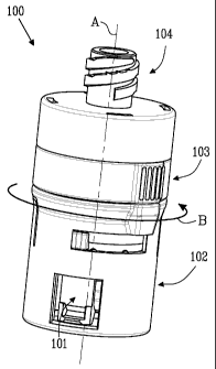
described in greater detail. Figure la shows a female piercing member
protection device
100 having a longitudinal axis A and a transverse axis B, for providing a
fluid
CA 02698939 2010-03-08
WO 2009/035383 PCT/SE2007/050643
7
communication between a first and a second fluid container. The female
piercing member
protection device 100 comprises a connection member 101 to connect to the
first fluid
container via a male connection part. The connection member 101 is at least
partly
enclosed by a turnable outer casing 102, which can be turned between a first
and a
second position. The first position in which the connection member 101 is
substantially
unable to slide along the longitudinal axis A, and a second position in which
the
connection member 101 is it substantially able to slide along the longitudinal
axis A. The
first position is an inactivated position in which the female piercing member
protection
device 100 fully protects the piercing member from exposure and at the same
time is
protected in terms of that the connection member 101 is substantially unable
to slide to an
activated position. The female piercing member protection device 100 also
comprises an
activated position in which the piercing member is exposed so as to provide
for a fluid
communication between the first and the second fluid container. The activated
position
can only be reached when the outer casing 102 has been turned to the second
position,
and the connection member 101 is moved along the longitudinal axis A to the
activated
position.
The outer casing 102 is arranged to cover the connection member 101 so as to
provide
for a protective sleeve, in which the connection member may slide. A locking
ring 103 is
arranged around the periphery of the outer casing and function as a second
locking
device which can substantially prevent the connection member from sliding
between the
activated and inactivated position by means of being turned between a locked
position
and an unlocked position. Connection means 104 is arranged opposite the
connection
member 102 to the outer casing 102 so as to allow for the connection to the
second fluid
container. A piercing member (not shown) is arranged to the connection means
104 so as
to provide for fluid communication between a first and a second fluid
container.
In figure 2, each component is shown in an exploded view along the
longitudinal axis A,
and will be described in greater detail below.
Turning first to the outer casing 102, the outer casing 102 comprises a first
and a second
side 110, 111, an inner and an outer side 112, 113 and have substantially the
form of a
hollow cylinder. At least one aperture 114 is arranged in the proximity of the
second end
111 of the outer casing 102. The aperture 114 is substantially rectangular
with a first and
a second longitudinal side 115, 116 and a first and a second transverse side
117, 118.
CA 02698939 2010-03-08
WO 2009/035383 PCT/SE2007/050643
8
The aperture 114 is intended to be assembled in working cooperation with a
locking
flange arranged on the connection member 101.
A straight channel 120 having a first and a second end 121, 122 is arranged in
the outer
casing 102, extending trough the outer casing 102. The straight channel 120
further
extends from the first side 110 of the outer casing towards the second end 111
of the
outer casing 102 and passes the middle of the outer casing 102, with respect
to the
longitudinal axis A of the outer casing 102. The straight channel 120 stops
just above the
aperture 114, with respect to the longitudinal axis A. The straight channel
120 comprises
an assembly part 123 and a working part 124. The assembly part 123 and the
working
part 124 are separated by a connection member locking channel 125 which
extends
substantially perpendicular from the middle of the straight channel 120, along
the outer
casing 102. Additionally, an activation and inactivation positioning channel
126 extends
substantially perpendicular along the outer casing 102, from the second end
122 of the
straight channel 120. The connection member locking channel 125 extends
slightly
shorter along the outer casing 102 than the positioning channel 126.
Altogether, the
straight channel 120, the connection member locking channel 125 and the
positioning
channel 126 substantially form an F-shaped channel system. The outer casing
can
preferably be turned 5-180 , more preferably 20-120 , most preferred 40-95 ,
between the
first and second position.
A stop flange 127 is arranged between the connection member locking channel
125 and
the positioning channel 126. The stop flange 127 extends around the periphery
of the
outer casing 102 and crosses the working part 124 of the straight channel 120.
After the
outer casing 102 has been assembled with the connection member 101, a locking
ring
103 is placed adjacent the stop flange 127 and around the periphery of the
outer casing
102. The stop flange 127 prevents the locking ring 103 from sliding along the
longitudinal
axis A in a direction towards the second side 111 of the outer casing 102.
Further shown in figure 2 is the connection member 101. The connection member
101
comprises a substantially hollow cylinder sleeve which has an outer diameter
slightly less
than the inner diameter of the outer casing. During assembly with the outer
casing 102,
the connection member 101 is inserted into the outer casing from the first
side 110 of the
outer casing 102. The connection member 101 comprises a first and a second
side 130,
131 and an inner and an outer side 132, 133. A circumferential flange 134
extends around
the periphery of the connection member 101 at the first side 130 of the
connection
CA 02698939 2010-03-08
WO 2009/035383 PCT/SE2007/050643
9
member 101. A protrusion 135 protrudes out from the periphery of the
circumferential
flange 134 of the connection member 101. The protrusion 135 is during assembly
intended to slide into the assembly part 123 of the straight channel 120 and
to operate in
the connection member locking channel 125 and the positioning channel 126 as
well as
the working part 124, during use of the female piercing member protection
device 100.
At least one deformable locking flange 136 is arranged substantially parallel
with the
longitudinal axis A. The deformable locking flange 136 comprises a first and a
second
longitudinal side 137, 138 and a first and a second transverse side 139, 140.
The first
transverse side 139, which is an integrated part of the connection member 101,
is
arranged in the proximity of the middle of the connection member 101, with
respect to the
longitudinal axis A. Hence the deformable locking flange 136 is an integrated
part of the
connection member 102. The deformable locking flange 136 extends from the
middle of
the connection member 101 to the second side 131 of the connection member 101.
Small
channels separate, and form, the first and the second longitudinal side 137,
138 from the
connection member 101. After assembly, the deformable locking flange 136 of
the
connection member 101 is intended to be in working cooperation with the
aperture 114 of
the outer casing 102, and to lock onto a male connection member, as will be
described
below.
The aperture 114 of the outer casing and the deformable locking flange 136 of
the
connection member 101 has been described in singular; however, in a preferred
embodiment of the present invention, the outer casing comprises at least two
opposing
apertures 114 and at least two opposing deformable locking flanges 136.
The locking ring 103 is in the form of a ring-like sleeve member comprising an
outer and
an inner surface 150, 151 and a first and a second transverse side 152, 153. A
locking
protrusion 154 (shown in figure 3 to 7) protrudes between the first and the
second side
152, 153 from the inner surface 151 of the locking ring 103. The locking ring
comprises an
inner diameter 155 which is large enough for the locking ring 103 to snugly
fit around the
outer casing 102 after assembly. The distance between the first and the second
side 152,
153 of the locking ring 103 is substantially smaller than the length of the
inner diameter
155 providing the substantially ring-like form to the locking ring 103. The
outer surface
150 of the locking ring 103 comprises at least one grip protrusion 156 which
extends out
from wall of the locking ring 103. Preferably is a plurality of grip
protrusions arranged on
the locking ring 103. Such a grip protrusion aids a user during turning of the
locking ring
CA 02698939 2010-03-08
WO 2009/035383 PCT/SE2007/050643
103. Alternatively, the grip protrusion is replaced with a see-through opening
which would
in the shown embodiment of the present invention be aligned with the
protrusion 154 and
run substantially parallel with the protrusion 154. Such see-through opening
can be
covered with a protective window if necessary. The purpose of the see through
opening
5 156 is for a user to have an indication of whether the locking ring 103 is
in the locked or
unlocked position. As an alternative to a see through opening, the locking
ring 103 can be
manufactured from a transparent material.
A piercing member 105 in the form of a hollow needle comprises a first and a
second end
160, 161 and an envelope surface 162. The first end 160 comprises a piercing
tip 163
10 intended to pierce a male connector of a fluid container during use. A
fluid outlet opening
164 is arranged in the proximity of the piercing tip 163, a fluid inlet
opening 165 is
arranged at the second end 161. Although the terms outlet and inlet openings
are used,
the openings and the piercing member 105 are not restricted to a one way flow.
The connection means 104 comprises a threaded portion 170 extending along the
longitudinal axis A and arranged so that a fluid container can be attached to
the
connection means 104. The threaded portion 170 comprises an opening (not
shown) into
which the second end 161 of the piercing member 105 can be arranged so that
the fluid
inlet opening 165 is in fluid communication with a fluid container after
connection. The
threaded portion 170 is in the shown embodiment a conventional luer-lock
arrangement. A
sleeve member 171 is arranged to the threaded portion 170. The sleeve member
171
comprises a first and a second transverse side 172, 173 extending
substantially
transverse to the longitudinal axis A, an outer and an inner surface 174, 175.
The
threaded portion is arranged substantially in the centre of the first
transverse side 172 of
the sleeve member 171 which comprises a larger diameter than the threaded
portion 170.
The sleeve member 171 is further arranged with an assembly opening (not shown)
at the
second end 173 of the sleeve portion. The assembly opening extends
substantially from
the second transverse side 173 to the proximity of the first transverse side
172 of the
sleeve member 171. After assembly, the assembly opening is intended to partly
encompass at least the first side 110 of the outer casing 102.
Additionally in figure 2 is a first and a second barrier member shown; which
will be
described in greater detail below.
CA 02698939 2010-03-08
WO 2009/035383 PCT/SE2007/050643
11
Figure 3 shows a cross section of the earlier described embodiment of the
present
invention after assembly. More specifically figure 3 shows the female piercing
member
protection device 100 with a longitudinal axis A, and comprising a connection
member
101, an outer casing 102 arranged to cover the connection member 101 so as to
provide
for a protective sleeve. A locking ring 103 is arranged around the periphery
of the outer
casing 102 and function as a second locking device which can substantially
prevent the
connection member from sliding between an activated and an inactivated
position along
the longitudinal axis A. Connection means 104 is arranged to the outer casing
102 so as
to permit for the connection to the second fluid container. A piercing member
105 is
arranged to the connection means 104 so as to provide for fluid communication
between
a first and a second fluid container during use.
The connection member 101 comprises as described above a first and a second
side 130,
131 and an inner and an outer side 132, 133. A circumferential flange 134
extends around
the periphery of the connection member 101 at the first side 130 of the
connection
member 101. A protrusion 135 protrudes out from the periphery of the
circumferential
flange 134 of the connection member 101.
The locking flange 136 which is arranged substantially parallel with the
longitudinal axis A,
comprises, as mentioned, a first and a second transverse side 139, 140. In the
proximity
of the second transverse side 140 of the locking flange 136, the locking
flange 136
comprises a hook like configuration, in the shown embodiment, the hook like
configuration
comprises a fold portion 141 which together with the locking flange 136
provide a snap-on
connection to a male connection part. The second transverse side 140 of the
locking
flange comprises a substantially transverse portion, with respect to the
longitudinal axis A,
which continues with an angle towards the longitudinal axis A to a folding tip
142, and
then continues away from the longitudinal axis A, back to run substantially
parallel with
the longitudinal axis A. As mentioned, the folding tip 142 points towards the
longitudinal
axis A.
The locking flange 136 of the connection member 101 is as mentioned in working
cooperation with the aperture 114 of the outer casing 102. As can be seen in
figure 3, the
connection member comprises two locking flanges 136 which are arranged to be
in
working cooperation with two apertures 114 on the outer casing 102. This
working
cooperation will be described in greater detail with reference to figure 5
below.
CA 02698939 2010-03-08
WO 2009/035383 PCT/SE2007/050643
12
The connection member 101 is further arranged with a first and a second
barrier member
143, 144 arranged so as to intersect the longitudinal axis A. The first and
the second
barrier member 143, 144 each has a substantially disc shaped form and
respectively
comprises a first and a second transverse side 145, 146, 147, 148. While being
arranged
substantially parallel with respect to each other, the space between the
second transverse
side 146 of the first barrier member 143 and the first transverse side 147 of
the second
barrier member 144 form a piercing tip protection chamber 149. As is shown in
figure 3,
the second end 161 of the piercing member is attached to the connection means
104,
permitting the piercing member 105 to extend aligned with the longitudinal
axis A, and
partly through the first barrier member 143, to the piercing tip protection
chamber 149.
The piercing tip 163 of the piercing member 105 is arranged in the piercing
tip protection
chamber 149. The outlet opening 164 of the piercing member 105 is positioned
at least
partly inside the first barrier member 143 so as to provide for a protective
lid to the outlet
opening 164 of the piercing member 105. The piercing tip 163 may however be
positioned
fully inside the first barrier member 143, or fully inside the piercing tip
protection chamber
149.
The first and second barrier members 143, 144 has been described as two
separate
barrier members, however, the two separate barrier member can be replaced with
one
barrier member comprising a piercing tip protection chamber, or with a barrier
member
without a piercing tip protection chamber.
In one embodiment, a piercing member protection device comprises a piercing
member,
wherein said piercing member comprises a fluid opening in the proximity of a
piercing tip,
at least one barrier member is arranged to the piercing member protection
device wherein
the fluid opening of the piercing member is fully enclosed in the barrier
member, so that
the barrier member provides a fluid leakage protection device for the piercing
member
protection device. The piercing member protection device is preferably a
female piercing
protection device.
The outer casing 102 can, as mentioned above, be turned between a first
position and a
second position, wherein when the outer casing 102 is in its first position;
the male
connection part can be attached with a snap-on connection to the connection
member
101. In the first position the male connection member may also be released
from the
snap-on connection, however, such detachment needs a certain force in order to
overcome the snap-on connection. When the outer casing 102 is in its second
position,
CA 02698939 2010-03-08
WO 2009/035383 PCT/SE2007/050643
13
the locking flanges 136 of the connection member 101 are displaced from the
apertures
114 of the outer casing 102, this will be described in greater detail below.
Further in figure 3, the locking ring 103 is arranged circumferentially around
the outer
surface 113 of the outer casing 102 and is positioned between the stop flange
127 of the
outer casing 102 and the connection means 104. The connection means 104 is
attached
in the proximity of the first side 110 of the outer casing 102.
In figure 4a and 4b a male connection part will be described in greater
detail. The male
connection part may form a permanent or a temporarily connection part on e.g.
a fluid
container such as an infusion bag, infusion line, or the like, e.g. by means
of a luer-lock,
spike device, welding means, molding or adhesive means. The male connection
part 200
comprises a longitudinal cylinder like body 201 having a longitudinal axis C.
The male
connection part 200 further comprises a first and a second side 202, 203, an
outer and an
inner surface 204, 205. At the first side of 202 of the male connection part
200 is a
transverse locking flange 206 arranged. The transverse locking flange 206
extends
around the periphery of the outer surface 204 of the male connection part 200
and is
intended to cooperate with the locking flange 136 of the connection member
101.
In the shown embodiment of the male connection part 200, a circumferential
wall 207
surrounds the first end 202 of the male connection part 200, as shown in
figure 4b. The
circumferential wall 207 is arranged to at least partly encompass at least a
part of the
second barrier member 144 of the connection member 101 after connection, to
provide for
a steady and rigid connection between the parts, as well as provide a
protective wall
against negative handling, e.g. touching, which might lead to damages of e.g.
a barrier
member 208. The barrier member 208 is arranged at the centre of the first side
202 of the
male connection member 200, intersecting the longitudinal axis C. The barrier
member
208 of the male connection part 200 is after assembly with the female piercing
member
protection device 100 intended to provide for a double barrier member coupling
together
with the second barrier member 144 of the connection member 101. A fluid
communication channel 210 (not shown), formed by the inner surface 205,
extends from
the barrier member 208 of the male connection part 200 to the second side 203
of the
male connection part 200.
The male connection part 200 can further be arranged with at least one turning
grip
protrusion. In the shown embodiment, the male connection part 200 is equipped
with 3
CA 02698939 2010-03-08
WO 2009/035383 PCT/SE2007/050643
14
turning grip protrusions 209. The turning grip protrusions 209 are arranged on
the outer
surface of the circumferential wall 207, permitting the turning grip
protrusions 209 to
interact with the inner side 132 of the connection member 101. The tree
turning grip
protrusions 209 are symmetrically spread around the outer surface of the
circumferential
wall 207 so as to permit a good grip, and to prevent that more than one
turning grip
protrusions 209 will be positioned on the locking flange 136 of the connection
member
101. They further run substantially along the longitudinal axis C at least
along a part of the
circumferential wall 207.
In those cases the male connection part 200 is arranged with turning grip
protrusions, the
inner side of the connection member is preferably arranged with corresponding
turning
grip grooves (not shown). The number of turning grip protrusions 209 on the
male
connection part 200 may be from 1 to 20, preferably 2-10, more preferably 3-8,
generally
symmetrically spread around the circumferential wall 207 or any other suitable
part of the
connection member 200. The number of turning grip grooves, also they generally
symmetrically spread around the inner surface 132 of the connection member
101, may
be from 1 to 19, preferably 1-9, more preferably 2-7. Most preferably, the
number of
turning grip protrusions 209 are more than the number of turning grip grooves,
preferably
one more. The purpose of the turning grip protrusions 209 is to prevent the
connection
member 101 from turning with respect to the male connection part 200 after
assembly,
this in turn will provide for a safe turning, with respect to the outer casing
102. The male
connection part thereby provides for an increased turning friction between the
female
piercing member protection device, and especially the connection member, after
assembly.
In figure 5, the female piercing member protection device 100 and the male
connection
part 200 assembly, and the cooperation there between, will be described. As
mentioned
above, the outer casing 102 can be turned between a first and a second
position. In its
second position, the locking flanges 136 of the connection member 101 are
displaced
from the apertures 114 of the outer casing 102. Figure 5 is illustrated after
turning the
outer casing 102 to the second position.
As shown in figure 5, the male connection part 200 has been inserted into the
female
piercing member protection device 100. During insertion of the male connection
part 200,
the locking flanges 136 will slightly deform out in a radial direction, with
respect to the
longitudinal axis A, leaving space for the male connection part 200. The fold
portion 141 is
CA 02698939 2010-03-08
WO 2009/035383 PCT/SE2007/050643
initially displaced by the transverse locking flange 206, but as the folding
tip 142 has been
passed, the locking flanges 136 will return to its normal position and thereby
hold the male
connection part 200 in a firm grip. As the outer casing 102 has been turned to
its second
position and the apertures 114 has been displaced from the locking flanges
136, the
5 locking flanges 136 are substantially unable to deform out in a radial
direction, with
respect to the longitudinal axis A. The male connection part 200 is thereby
effectively
prevented from disconnecting from the connection member 101 and the female
piercing
member protection device 100, a secure and firm connection is thereby
established,
which protects a user from accidentally disconnect a fluid container during a
fluid transfer
10 and thereby expose the piercing member. The connection member 101 is still
in the
inactivated position, i.e. the piercing member has not yet penetrated the
barrier members
144 and 208 to provide for a fluid communication.
In figure 6 the male connection member 101 is positioned in the activated
position. As can
be seen both the first and the second barrier members 143, 144 are penetrated
by the
15 piercing member 105, the piercing tip 163 has reached inside the fluid
communication
channel 210 of the male connection part 200. The connection member 101 is now
in the
activated position.
At this point, the locking ring 103 which is arranged circumferentially around
the outer
surface 113 of the outer casing 102 can be turned between a first position (as
shown in
figure 5 and 6) to a second position (as shown in figure 7). While the locking
ring is in the
unlocked position, the connection member 101 can slide between the activated
position
(as shown in figure 6) to the inactivated position (as shown in figure 5),
however, when
the locking ring 103 is turned to the locked position the connection member
101 is
substantially unable to slide between the activated position (as shown in
figure 6) to the
inactivated position (as shown in figure 5). The locking mechanism of the
locking ring 103
is provided by means of the locking protrusion 154, which has been described
above.
The locking protrusion 154, which protrudes at least partly between the first
and the
second side 152, 153 from the inner surface 151 of the locking ring 103, runs
in a part of
the F-shaped channel system, which has been described above. More
specifically, the
locking protrusion 154 runs in the connection member locking channel 125 which
extends
perpendicular from the straight channel 120 of the outer casing 102. As can be
seen in
figure 3, 5 and 6 the locking protrusion 154 is positioned in the connection
member
locking channel 125, but displaced from the straight channel 120 so as to
permit the
CA 02698939 2010-03-08
WO 2009/035383 PCT/SE2007/050643
16
connection member 101 to reach its activated position. In figure 7 the locking
ring 103 has
been turned and the locking protrusion 154 has been moved to the connection
member
locking channel 125 so as to be positioned in the straight channel 120 and
thereby
effectively prevent the connection member 101 from being displaced from the
activated
position to the inactivated position.
The locking ring 103 or the locking protrusion 154 may further be arranged
with a bias
means (not shown), such as a spring, which will bias the locking protrusion
154 towards
the straight channel 120 so as to provide for an automatic locking mechanism.
If the
locking protrusion 154 is properly formed, e.g. by making an angled surface
towards the
activation and inactivation positioning channel 126 of the outer casing 102,
the locking
protrusion 154 can be made to automatically lock the connection member 101 in
the
active position. During movement of the connection member 101 to the active
position,
the locking protrusion is pushed way, however, after the connection member 101
has
passed the locking protrusion 154, the bias means bias the locking protrusion
154 back
into the straight channel 120 and thereby effectively prevent the connection
member 101
from returning to its inactive position. Hence the female piercing member
protection
device can be arranged with a manually second locking device, e.g. in which
the user
must turn the locking ring 103 himself to the locked position, or, an
automatic second
locking device, e.g. in which the locking ring 103 is automatically positioned
in the locked
position.
It is to be noted that the features described above may be combined in various
ways,
unless it is obviously inappropriate.