Note: Descriptions are shown in the official language in which they were submitted.
CA 02699095 2011-11-21
,. t
WO 2009/047386 PCT/F12008/050557
CENTRIFUGAL SEPARATOR ASSEMBLY
Technical field
The invention relates to centrifugal separators for separating solid particles
from
the process and product gases of fluidized bed reactors, especially
circulating flu-
idized bed reactors used for combustion or gasification of fuel material.
The invention particularly relates to a centrifugal separator assembly,
comprising
a polygonal separator chamber formed of planar wall sections joined with each
other to provide a substantially gas tight structure and having at least four
pairs of
planar opposite wall sections, the chamber including a tapered portion formed
by
having a first inward bending in each of the wall sections, the tapered
portion ex-
tending as a discharge channel for separated particles from the separator cham-
ber, which discharge channel is formed by means of first and second pairs of
op-
posite wall sections being perpendicular to each other.
Background art
It is known to manufacture cylindrical cyclones of a fluidized bed reactor as
a
cooled structure formed of parallel water tubes and having a conical bottom.
To
provide a water tube wall construction of cylindrical form and to connect it
to the
surrounding construction requires a lot of manual labour, which could be mini-
mized by using substantially planar walls.
US2007079773 discloses a rectangular cyclone in connection with a fluidized
bed
reactor made of tube walls. The construction of the conical part of the
cyclone is
such that each of the wall sections has a decreasing width i.e. triangular
shape,
and the edges of thereof have been joined to the adjacent edges of the other
wall
section.
CA 02699095 2011-11-21
WO 2009/047386 PCT/FI2008/050557
2
W02004063626 shows a heat exchange chamber having an enclosure with a ta-
pered portion of a vertical polygonal heat exchange chamber having more than
four sides with simple water tube panels in such a way that the various
tapered
portions may simultaneously taper inwardly in more than one horizontal
direction
and that the widths of all water tube panels remain substantially uniform in
the
tapered portions. In applications where the chamber is a cyclone separator of
a
fluidized bed reactor the outlet for separated solids remains considerably
wide in
cross sectional area. It has also been noticed that the form of tapered
portions
may be improved.
An object of the invention is to provide a centrifugal separator assembly,
which
has a tapered portion and a channel for the discharge of separated particles
from
the separator, and which is thus less space consuming and better adaptable to
the requirements for handling the solid material in a fluidized bed reactor
and its
accessories.
Disclosure of the invention
Objects of the invention are met substantially as is disclosed herein.
According to a preferred embodiment of the invention, a centrifugal separator
as-
sembly comprises a polygonal separator chamber formed of planar wall sections
joined with each other to provide a substantially gas tight structure and
having at
least four pairs of planar opposite wall sections, the chamber including a
tapered
portion formed by having a first, inward bending in each of the wall sections,
the
tapered portion extending as a discharge channel for separated particles from
the
separator chamber, which discharge channel is formed by means of first and
second pairs of opposite wall sections being substantially perpendicular to
each
other. It is a characteristic feature of the invention that in the discharge
channel
for separated particles the first pair of wall sections extends into the area
between
the second pair of wall sections.
CA 02699095 2010-03-09
WO 2009/047386 PCT/F12008/050557
3
Thus, the distance between the first pair of opposite wall sections is less
than the
width of the second pair or opposite wall sections in the area of the
discharge
channel. Preferably the first pair or wall sections extends in tapering
direction into
the area between the second pair of wall sections.
This makes it possible to have a considerably small cross sectional area of
the
discharge channel, making the handling of separated particles straightforward.
Preferably, a gas seal arrangement and means for introducing fluidization gas
are
provided in connection with a lower section of the first pair of opposite wall
sec-
tions. In this way, the space between the discharge for the separated
particles
and the gas seal in the return duct is considerably small and, thus, the
amount of
the accumulated solids is also small. This construction brings the benefit of
hav-
ing a smaller load caused by the weight of the particles to the structure.
The first pair of opposite wall sections and the second pair of opposite wall
sec-
tions include a first bending and a second bending for forming the tapering
por-
tion. According to a preferred embodiment of the invention, the distance
between
the first and the second bendings in the first pair of wall sections is longer
than
the distance between the first and the second bendings in the second pair of
wall
sections.
Preferably each wall section has a constant width over the length of the
separator
chamber. This brings the benefit that all tubes in the wall section may extend
through the whole length of the wall section, i.e. there is no need for tube
take-
out, like if the wall section were made tapering.
According to an embodiment of the invention, the first pair of wall sections
is pro-
vided with symmetrical bendings. This way, the vertical space required for the
ta-
pering portion of the separator is minimized.
The wall sections preferably comprise substantially evenly spaced tubes for ar-
ranging heat transfer medium flow through the wall sections when in use.
It is advantageous that all the wall sections are of equal width. This way the
con-
struction is easier and it contributes to modularized manufacturing.
CA 02699095 2010-03-09
WO 2009/047386 PCT/F12008/050557
4
With the present invention, it is possible to construct the cyclone separator
of pla-
nar walls of substantially constant width, and have substantially all tubes of
the
wall structure extending through the whole length.
Brief Description of Drawings
In the following, the invention will be described with the reference to the
accom-
panying schematic drawings, in which
Figure 1 illustrates a centrifugal separator assembly according to an
embodiment
of the invention,
Figure 2 illustrates a horizontal cross section II-II of figure 1,
Figure 3 illustrates a horizontal cross section III-III of figure 1,
Figure 4 illustrates a horizontal cross section IV-IV of figure 1,
Figure 5 illustrates a horizontal cross section V-V of figure 1,
Figure 6 illustrates a vertical cross section VI-VI of figure 1,
Figure 7 illustrates a centrifugal separator assembly according to another em-
bodiment of the invention, and
Figure 8 illustrates the detail 100 in figure 1.
Detailed Description of Drawings
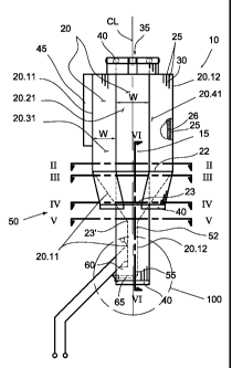
Figures 1 - 6 illustrate a centrifugal separator assembly 10 according to an
em-
bodiment of the invention. The separator assembly comprises a separator cham-
ber 15 enclosed by planar wall sections 20. The cross section of the separator
chamber is octagonal comprising four pairs of opposite wall sections 20.11,
20.12; 20.21, 20.22; 20.31, 20.32; 20.41, 20.42. The wall sections are manufac-
tured, e.g., by joining adjacent tubes 25 with each other and spaced by a fin
30 in
a manner known per se to form a gas tight construction. Preferably, each wall
section has a constant width W over the length of the separator chamber 15.
This
way the wall sections may be easily prefabricated in a similar manner.
CA 02699095 2010-03-09
WO 2009/047386 PCT/F12008/050557
Each wall section is provided with manifolds 40 at its ends, to which the
tubes are
connected. There may be common manifolds provided for several wall sections
but preferably each wall section is provided with individual manifolds (inlet
and
outlet). The wall sections are connected to the medium circulation of the
power
5 plant (not shown) in a manner designed case by case. Such a medium
circulation
is typically a steam cycle of the plant.
At the first end of the separator, which is the upper end, the adjacent wall
sec-
tions 20 are bent inwardly towards the centre axis so that a gas outlet
opening 35
is provided having a cross sectional area smaller than the cross sectional
area of
the separator chamber 15. The inner surface of the wall sections is preferably
lined with suitable heat and abrasion resistant lining 26 so that the cross
section
of the gas space is made substantially circular or at least the corners formed
when connecting the adjacent wall sections to each other are evened to make
the
inner surface substantially smooth.
The separator is provided with a gas inlet 45, through which hot gas and
particles
entrained therewith may be introduced into the gas chamber 15 of the cyclone
when in use.
The centrifugal separator chamber assembly also includes a tapered portion 50
at its second end formed by inwardly bent portions of the wall sections 20.
The
tapered portion provides a transition from the octagonal cross section of the
separator chamber 50 to rectangular shape of the discharge channel for sepa-
rated particles. Before the first bending 22, that is in the region of the
wall sec-
tions above the bending line, the cross sectional area of the chamber is
octagonal
as can be seen from Figure 2, which illustrates the view II-II of Figure 1.
Wall sec-
tion is illustrated for clarity reasons mainly by a solid line, but in
practise the wall
is typically manufactured of adjacent tubes 25 having a fin 30 between them.
Each wall section 20 is provided with a first bending 22 at a same
longitudinal
(vertical) position the bending lines being at the same level. First and
second
pairs of planar opposite wall sections 20.11, 20.12; 20.21, 20.22, between
which
third and fourth pairs of planar opposite wall sections 20.31, 20.32; 20.41,
20.42
CA 02699095 2010-03-09
WO 2009/047386 PCT/F12008/050557
6
are located, are bent towards the centre line CL of the separator chamber 15
in
an angle greater than the angle in which the third and the fourth pairs of
planar
opposite wall sections are bent. The third and fourth pairs of wall sections
are
bent against the edges of the first and second pairs of wall sections to cover
the
wedge shaped area between them. Figure 3 shows the sectional view III-III of
Figure 1 which illustrates that the first and the second pairs of planar
opposite
wall sections 20.11, 20.12; 20.21, 20.22 are closer to the central axis of the
sepa-
rator camber.
At least the first and second pairs of planar opposite wall sections 20.11,
20.12;
20.21, 20.22 are provided with a second bending 23, 23' in which the wall sec-
tions are bent again outwardly away from the centre line of the separator cham-
ber. Figure 4 showing the view IV-IV of Figure 1 illustrates the situation
just be-
fore the edges of the first and the second pairs of wall section reach each
other
and the second pair of wall sections 20.21, 20.22 will be provided with the
second
bending 23. Preferably, the wall sections before the first bending and after
the
second bending are on parallel planes. In other words, the areas outside the
re-
gion between the bendings are on parallel planes. The distance between the
first
bending 22 and the second bending 23' of the first pair of wall sections
20.11,
20.12 is made longer than the distance between the first bending 22 and the
sec-
and bending 23 of the second pair of wall sections 20.21, 20.22. Thus the
first
pair of wall sections 20.11, 20.12 extends in tapering direction into the area
be-
tween the second pair of wall sections 20.21, 20.22. This is illustrated in
Figure 5.
The first pair of wall sections 20.11, 20.12 extends between the second pair
of
wall sections 20.21, 20.22 forming a rectangular channel between them. The
edges 24 of the first pair of wall sections are substantially gas tightly
joint to the
surface 26 of the second pair of wall sections. This way the cross sectional
area
of the channel may be flexibly dimensioned for each application.
The first and the second pairs of planar wall sections form the discharge
channel
for separated particles as an extension of the tapered portion. The third and
the
fourth pairs of planar walls 20.31, 20.32; 20.41, 20.42 may have a second bend-
ing 23 at the same location as the second pair of wall sections, and extend
further
CA 02699095 2010-03-09
WO 2009/047386 PCT/F12008/050557
7
downwards but that does not effect the inner form of the tapering portion of
the
separator chamber.
Figure 1 and Figure 6 showing the view VI-VI of Figure 1 illustrate that the
first
and second pairs of opposite wall sections extend further downwards from the
second bending 23' of the first pair of opposite walls sections, thus forming
a rec-
tangular discharge channel 52. The first pair of wall sections 20.11, 20.12 is
con-
nected approximately at the end area thereof between the second pair of wall
sections 20.21, 20.22 forming a bottom part 55. The bottom part 55 is provided
with a gas seal 60 and means 65 for introducing fluidization gas in to the end
area of the channel comprising a wind box and gas nozzles. The detail 100 of
the
bottom part 55 is shown more in detail in Figure 8. The gas seal is provided
by
arranging an open area to the wall section 21.11 by bending tubes 60.1 out of
the
general plane of the wall in a manner known per se. The flow of separated
parti-
cles through the gas seal is illustrated by the arrow S in Figure 8. The
height of
the rectangular channel between the bottom part 55 and the tapered portion is
preferably limited to a height which is sufficient to provide the operation
and exis-
tence of the gas seal, which in practice means a capability to fluidize the
particles
in the bottom part 55.
It is also possible to provide a separator without a gas seal, as shown in
Figure 7.
The centrifugal separator assembly 10 in Figure 7 differs from that of Figure
1 in
the bendings of the first and second pairs of wall sections at their lower
ends. The
first pair of wall sections also forms two walls of a return duct extending,
e.g., to
the lower part of the fluidized bed reactor (not shown). Part of the second
pair of
wall sections 20.21, 20.22 forms two other walls of a return duct having the
tubes
bent to follow the return duct.
It is clear that the invention is not limited to the examples mentioned above
but
can be implemented in many different embodiments within the scope of the in-
ventive idea. It is also clear that the details mentioned in connection with
an em-
bodiment may be used in another embodiment when feasible.