Note: Descriptions are shown in the official language in which they were submitted.
CA 02699147 2010-04-07
METHODS AND DEVICES FOR PROVIDING ACCESS INTO A BODY CAVITY
FIELD OF THE INVENTION
[0001 ] The present invention relates to methods and devices for providing
surgical access into a
body cavity.
BACKGROUND OF THE INVENTION
[0002] Access ports are widely used in medical procedures to gain access to
anatomical cavities
ranging in size from the abdomen to small blood vessels, such as veins and
arteries, epidural,
pleural and subarachnoid spaces, heart ventricles, and spinal and synovial
cavities. The use of
access ports has become more common as they provide minimally invasive
techniques for
establishing a portal for a number of procedures, such as those involving the
abdominal cavity.
Reduced postoperative recovery time, markedly decreased post-operative pain
and wound
infection, and improved cosmetic outcome are well established benefits of
minimally invasive
surgery, derived mainly from the ability of surgeons to perform an operation
utilizing smaller
incisions of the body cavity wall.
[0003] In many surgical procedures, it is desirable to provide one or more
working channels into
a body cavity through which various instruments can be passed to view, engage,
and/or treat
tissue to achieve a diagnostic or therapeutic effect. In laparoscopic
abdominal procedures for
example, the abdominal cavity is generally insufflated with C02 gas to a
pressure of around 15
mm Hg. The abdominal wall is pierced and one or more tubular cannulas, each
defining a
working channel, are inserted into the abdominal cavity. A laparoscopic
telescope connected to
an operating room monitor can be used to visualize the operative field and can
be placed through
one of the working channels. Other laparoscopic instruments such as graspers,
dissectors,
scissors, retractors, etc. can also be placed through one or more of the
working channels to
facilitate various manipulations by the surgeon and/or surgical assistant(s).
[0004] One problem with existing methods and devices is that existing surgical
access devices
do not retract tissue beyond the initial incision to any appreciable degree.
It can thus be difficult
to position a surgical access device in the incision, particularly in
minimally invasive surgical
procedures where the incision is relatively small. It can also be difficult as
an initial matter to
-1-
CA 02699147 2010-04-07
choose an appropriately sized access device to position within the incision
during the stress and
time constraints of surgery.
[0005] It can also be difficult to remove an access device from an incision in
tissue when the
access device is snugly positioned therein, requiring an amount of pullout
force that can cause
damage to the tissue and/or prolong length of the surgical procedure. Such
forceful removal of
the access device can also increase the size of the incision, thereby reducing
the healing and
cosmetic benefits of a minimally invasive surgical procedure.
[0006] Accordingly, there remains a need for methods and devices for providing
surgical access
into a body cavity.
SUMMARY OF THE INVENTION
[0007] The present invention generally provides methods and devices for
providing surgical
access into a body cavity. In one embodiment, a surgical access device is
provided that includes
a proximal external portion, a distal portion including a flexible retractor
configured to be
positioned in tissue of a body to form a pathway therethrough into a body
cavity, and an
actuation member, e.g., a stability thread or actuation cable, spiraling
around a perimeter of the
retractor. The actuation member is configured to selectively effect a change
in a diameter of the
retractor.
[0008] In some embodiments, the device can include an actuator configured to
change a tension
of the actuation member to selectively effect the change in the diameter of
the retractor. The
actuator can have a variety of configurations, such as a ratchet mechanism.
The ratchet
mechanism can include a pawl configured to engage at least one of a plurality
of teeth and to be
movable to selectively effect the change in the diameter of the retractor. The
pawl can be
configured to be freely slidably movable in a first direction to selectively
effect the change in the
diameter of the retractor and to be prevented from moving in a second,
opposite direction. The
pawl can be configured to move radially inward relative to the retractor to
disengage the pawl
from engagement with the at least one of a plurality of teeth to allow the
pawl to move in the first
direction or the second direction to engage at least one other of the
plurality of the teeth.
-2-
CA 02699147 2010-04-07
[0009] The device can vary in any other number of ways. For example, a first
terminal end of
the actuation member can be attached to a distal end of the retractor and a
second terminal end of
the actuation member extends through the proximal external portion. For
another example,
selectively effecting the change in the diameter of the retractor can not
substantially change a
longitudinal length of the retractor. For yet another example, the retractor
can have a lumen
extending through a sidewall thereof, and the actuation member can be disposed
in the lumen.
For still another example, the retractor in a default state can have a first
diameter, and actuating
the actuation member with the retractor in the default state can move the
retractor to a second
state in which the retractor has a second diameter that is less than or
greater than the first
diameter.
[0010] In another aspect, a method of providing access through tissue to a
body cavity is
provided that includes positioning a retractor in an opening in tissue such
that a working channel
of the retractor provides access through the tissue and into a body cavity,
and moving an
actuation member extending around a perimeter of the working channel to change
a length of the
actuation member extending around the perimeter of the working channel and to
change a size of
a diameter of the retractor. In some embodiments, the method can include
locking the actuation
member in a fixed position relative to the retractor to maintain the size of
the opening in tissue.
The method can vary in any other number of ways. For example, changing the
length of the
actuation member extending around the perimeter of the working channel can
include selectively
increasing or decreasing the length of the actuation member extending around
the perimeter of
the working channel. For another example, moving the actuation member
extending around the
perimeter of the working channel can include moving a pawl coupled to the
actuation member in
a radial direction relative to the retractor.
[0011] In another embodiment, a method of providing access through tissue to a
body cavity
includes positioning a flexible retractor having a cross-sectional shape in
the form of an ellipse in
an opening in tissue such that the retractor forms a pathway through the
tissue and into a body
cavity and such that a major axis of the ellipse is substantially parallel to
a major axis of the
opening in tissue, and positioning the major axis of the ellipse substantially
perpendicular to the
major axis of the opening in tissue to expand the opening in tissue. The
method can have any
number of variations. For example, expanding the opening in tissue can include
moving the
-3-
CA 02699147 2010-04-07
opening in tissue from a linear shape to a substantially circular shape. For
another example,
positioning the major axis of the ellipse substantially perpendicular to the
major axis of the
opening in tissue can cause the flexible retractor to change from having the
cross-sectional shape
in the form of an ellipse to having a cross-sectional shape in the form of a
circle. For still
another example, positioning the flexible retractor in the opening in tissue
can include aligning at
least one of a plurality of rings disposed around a perimeter of the retractor
within the opening in
tissue. Positioning the major axis of the ellipse substantially perpendicular
to the major axis of
the opening in tissue can cause the at least one of the plurality of rings to
move from an elliptical
shape to a circular shape. Each of the plurality of rings can have an
elliptical shape at least when
the retractor is in a first state and not subjected to a compressive force.
BRIEF DESCRIPTION OF THE DRAWINGS
[0012] The invention will be more fully understood from the following detailed
description
taken in conjunction with the accompanying drawings, in which:
[0013] FIG. I is a side view of one embodiment of a surgical access device
having a plurality of
rings disposed around a retractor of the device;
[0014] FIG. 2 is a side, cross-sectional view of the device of FIG. 1;
[0015] FIG. 3 is a side, partially cross-sectional view of the device of FIG.
1 positioned in tissue
with a surgical instrument inserted through the device;
[0016] FIG. 4 is a side, partially cross-sectional view of one embodiment of a
surgical access
device having a plurality of angled rings disposed around a retractor of the
device;
[0017] FIG. 5 is a perspective view of one embodiment of a surgical access
device having a
retractor with an elliptical cross-sectional shape;
[0018] FIG. 6- is a side view of the device of FIG. 5 showing a major axis
length of the retractor;
[0019] FIG. 7 is a side view of the device of FIG. 5 showing a minor axis
length of the retractor;
[0020] FIG. 8 is a distal end view of the device of FIG. 5;
-4-
CA 02699147 2010-04-07
[0021 ] FIG. 9 is a distal end view of the device of FIG. 5 positioned in an
opening in tissue with
a major axis of the retractor being substantially parallel to a major axis of
the opening;
[0022] FIG. 10 is a distal end view of the device of FIG. 5 rotated from its
position in the tissue
of FIG. 9 with a minor axis of the retractor being substantially parallel to
the major axis of the
opening in tissue;
[0023] FIG. 11 is a side, partially cross-sectional view of one embodiment of
a retractor of a
surgical access device having a mechanically adjustable diameter;
[0024] FIG. 12 is a side, partially cross-sectional view of another embodiment
of a retractor of a
surgical access device having a mechanically adjustable diameter;
[0025] FIG. 13 is a side cross-sectional view of one embodiment of a surgical
access device
having a mechanically adjustable and lockable diameter;
[0026] FIG. 14 is an exploded cross-sectional view of a housing of the device
of FIG. 13;
[0027] FIG. 15 is a partially cross-sectional, proximal end view of the device
of FIG. 13; and
[0028] FIG. 16 is a side, partially cross-sectional view of the housing of the
device of FIG. 13.
DETAILED DESCRIPTION OF THE INVENTION
[0029] Certain exemplary embodiments will now be described to provide an
overall
understanding of the principles of the structure, function, manufacture, and
use of the devices
and methods disclosed herein. One or more examples of these embodiments are
illustrated in the
accompanying drawings. Those skilled in the art will understand that the
devices and methods
specifically described herein and illustrated in the accompanying drawings are
non-limiting
exemplary embodiments and that the scope of the present invention is defined
solely by the
claims. The features illustrated or described in connection with one exemplary
embodiment may
be combined with the features of other embodiments. Such modifications and
variations are
intended to be included within the scope of the present invention.
[0030] Various exemplary methods and devices are provided for providing
surgical access into a
body cavity. In general, the methods and devices allow a surgical access
device to be securely
-5-
CA 02699147 2010-04-07
positioned within an opening in tissue to provide access to a body cavity
underlying the tissue.
In one embodiment, a surgical access device can include a proximal housing and
a distal
retractor. At least one stability thread can extend around a perimeter of at
least a portion of the
distal retractor to provide structural integrity to the distal retractor and
help secure the device
within an opening formed in the tissue. In some embodiments, the stability
thread can be
mechanically adjustable to change a diameter of the distal retractor, thereby
allowing the device
to adapt to different sized openings in tissue and to be more easily
positioned therein and
removed therefrom. The surgical access device can provide active retraction of
the opening
formed in tissue to help securely position the device within the tissue. Such
secure positioning
can help form a better seal between the tissue and the device and help retain
the tissue in a more
stable position when the device is positioned therein. The device can also
dilate the tissue when
positioned therein to help improve the seal integrity between the device and
the tissue. Such
dilation of the tissue by the device can increase a size and/or change the
shape of the opening in
the tissue to increase working space available through the tissue opening.
Having more working
space through the tissue can help reduce interference between multiple
surgical instruments
inserted therethrough and/or allow larger and/or a greater number of surgical
instruments to be
inserted therethrough.
[0031 ] The various surgical access devices described herein can generally be
configured to allow
one or more surgical instruments to be inserted therethrough through one or
more independent
sealing ports or access ports formed in a proximal housing, hereinafter
generally referred to as a
housing, of the device and into a body cavity. The sealing ports can each
define working
channels extending through the proximal housing and aligned with a distal
retractor. The distal
retractor, hereinafter generally referred to as a retractor, can be configured
as a wound protector,
or other member for forming a pathway through tissue. The retractor can extend
from the
proximal housing of the device, and it can be configured to be positioned
within an opening in a
patient's body, such as the umbilicus. Any and all of the surgical access
devices described
herein can also include various other features, such as one or more
ventilation ports to allow
evacuation of smoke during procedures that utilize cautery, and/or one or more
insufflation ports
through which the surgeon can insufflate the abdomen to cause
pneumoperitenium, as described
by way of non-limiting example in U.S. Patent Application No. 2006/0247673
entitled
"Multi-port Laparoscopic Access Device" filed November 2, 2006, which is
hereby incorporated
-6-
CA 02699147 2010-04-07
by reference in its entirety. The insufflation port can be located anywhere on
the device, can
have any size, and can accept a leur lock or a needle, as will be appreciated
by those skilled in
the art.
[0032] Any and all embodiments of a surgical access device can also include
one or more safety
shields positioned through, in, and around any of the components and/or tissue
to protect the
components against puncture or tear by surgical instruments being inserted
through the device.
Exemplary embodiments of safety shields are described in more detail in U.S.
Patent Publication
No. 2006/0247673 entitled "Multi-port Laparoscopic Access Device" filed
November 2, 2006,
U.S. Patent Application No. 12/399,625 entitled "Methods and Devices for
Providing Access to
a Body Cavity" filed on March 6, 2009, U.S. Patent Application No. 12/399,482
entitled
"Methods and Devices for Providing Access to a Body Cavity" filed on March 6,
2009, and U.S.
Patent Application No. 12/242,765 entitled "Surgical Access Device" filed on
September 30,
2008, which are hereby incorporated by reference in their entireties.
[0033] In any and all of the surgical access device embodiments disclosed
herein, an engagement
and/or release mechanism can be included to allow certain components of the
surgical access
device to be removable as needed. Any engagement and release mechanism known
in the art,
e.g., a snap-lock mechanism, corresponding threads, etc., can be used to
releasably mate
components of the device. Exemplary embodiments of an engagement and release
mechanisms
are described in more detail in previously mentioned U.S. Patent Application
No. 12/242,765
entitled "Surgical Access Device" filed on September 30, 2008, U.S. Patent
Application No.
12/399,625 entitled "Methods and Devices for Providing Access to a Body
Cavity" filed on
March 6, 2009, and U.S. Patent Application No. 12/399,482 entitled "Methods
and Devices for
Providing Access to a Body Cavity" filed on March 6, 2009 and in U.S. Patent
No. 7,371,227
entitled "Trocar Seal Assembly," issued May 13, 2008 and U.S. Patent No.
5,628,732 entitled
"Trocar With Improved Universal Seal," issued May 13, 2007, which are hereby
incorporated by
reference in their entireties.
[0034] In use, as further discussed below, the surgical access devices
disclosed herein can be
used to provide access to a patient's body cavity. The device's retractor is
positionable within an
opening in a patient's body such that a distal portion of the retractor
extends into a patient's body
-7-
CA 02699147 2010-04-07
cavity and a proximal portion configured to couple to the device's housing is
positioned adjacent
to the patient's skin on an exterior of the patient's body. A lumen in the
retractor can form a
pathway through the opening in a patient's body so that surgical instruments
can be inserted
from outside the body to an interior body cavity. The elasticity of the skin
of the patient can
assist in the retention of the retractor in the body opening or incision made
in the body. The
retractor can be placed in any opening within a patient's body, whether a
natural orifice or an
opening made by an incision. As a non-limiting example, the retractor can be
placed through the
umbilicus. In one embodiment, the retractor can be substantially flexible so
that it can easily be
maneuvered into and within tissue as needed. In other embodiments, the
retractor can be
substantially rigid or substantially semi-rigid. The retractor can be formed
of any suitable
material known in the art, e.g., silicone, urethane, thermoplastic elastomer,
and rubber.
[0035] Typically, during surgical procedures in a body cavity, such as the
abdomen, insufflation
is provided through the surgical access device to expand the body cavity to
facilitate the surgical
procedure. Thus, in order to maintain insufflation within the body cavity,
most surgical access
devices include at least one seal disposed therein to prevent air and/or gas
from escaping when
surgical instruments are inserted therethrough. Various sealing elements are
known in the art,
but typically the surgical access device can include at least one instrument
seal that forms a seal
around an instrument disposed therethrough, but otherwise does not form a seal
when no
instrument is disposed therethrough; at least one channel seal or zero-closure
seal that seals the
working channel created by the sealing port when no instrument is disposed
therethrough; or a
combination instrument seal and channel seal that is effective to both form a
seal around an
instrument disposed therethrough and to form a seal in the working channel
when no instrument
is disposed therethrough. A person skilled in the art will appreciate that
various seals known in
the art can be used including, e.g., duckbill seals, cone seals, flapper
valves, gel seals, diaphragm
seals, lip seals, iris seals, etc. A person skilled in the art will also
appreciate that any
combination of seals can be included in any of the embodiments described
herein, whether or not
the seal combinations are specifically discussed in the corresponding
description of a particular
embodiment. Exemplary embodiments of various seal protectors are described in
more detail in
U.S. Patent No. 5,342,315 entitled "Trocar Seal/Protector Assemblies," issued
August 30, 1994
and U.S. Patent No. 7,163,525 entitled "Duckbill Seal Protector," issued
January 16, 2007,
which are hereby incorporated by reference in their entireties.
-8-
CA 02699147 2010-04-07
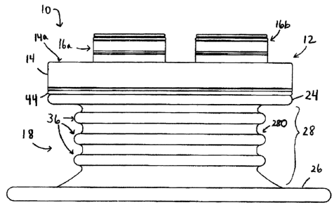
[0036] In an exemplary embodiment, shown in FIGS. 1 and 2, a surgical access
device 10 is
provided having a housing 12 configured to have one or more surgical
instruments inserted
therethrough. Although the housing 12 can have any configuration, in this
illustrated
embodiment, the housing 12 includes a seal base 14 that supports at least one
sealing or access
port and that is configured to form a seat and seal between the base 14 and a
distal portion of the
device 10, e.g., a retractor 18. The housing 12 can be fixedly or removably
coupled to the
retractor 18 configured to distally extend from the housing 12 and to provide
a pathway through
tissue into a body cavity. In this embodiment, the retractor 18 includes a
proximal retractor
portion or proximal retractor base 20 coupled to a distal retractor portion
22. As shown in this
embodiment, the housing 12 can be removably coupled via snap-fit to the
retractor 18. The
housing 12 can be in a fixed position relative to the retractor 18 as shown in
this embodiment, or
the housing 12 can be movable relative to the retractor 18. Exemplary
embodiments of various
housings are described in more detail in previously mentioned U.S. Patent
Publication No.
2006/0247673 entitled "Multi-port Laparoscopic Access Device" filed November
2, 2006, U.S.
Patent Application No. 12/399,625 entitled "Methods and Devices for Providing
Access to a
Body Cavity" filed on March 6, 2009, U.S. Patent Application No. 12/399,482
entitled "Methods
and Devices for Providing Access to a Body Cavity" filed on March 6, 2009, and
U.S. Patent
Application No. 12/242,765 entitled "Surgical Access Device" filed on
September 30, 2008, and
in U.S. Patent Application No. 12/399,547 entitled "Surgical Access Devices
And Methods
Providing Seal Movement In Predefined Paths" filed on March 6, 2009, which is
hereby
incorporated by reference in its entirety.
[0037] While any number of sealing ports can be formed in the seal base 14, in
this illustrated
embodiment, first and second sealing ports 16a, 16b extend through the seal
base 14. The
sealing ports 16a, 16b in this illustrated embodiment each have a central axis
that extends
substantially perpendicular to a proximal surface 14a of the seal base 14, and
the sealing ports
16a, 16b are each in a fixed position relative to the housing 12, but any one
or more of the
sealing ports can be angled relative to the seal base 14 and/or rotatable or
otherwise movable
relative to the seal base 14 and/or other portion(s) of the housing 12.
Additionally or
alternatively, any one or more of the sealing ports 16a, 16b can be configured
to be movable
relative to any one or more portions of the retractor 18 and/or any others of
the sealing ports 16a,
16b. The sealing ports 16a, 16b can be attached or mated to the seal base 14
using any
-9-
CA 02699147 2010-04-07
attachment or mating mechanism known in the art, but in the illustrated
embodiment the sealing
ports 16a, 16b can each mate with the seal base 14 through an interference
fit. In general, the
sealing ports 16a, 16b can each include a port housing, which can be seated
directly or indirectly
in a port opening in the seal base 14, and a sealing element, which can be
positioned within an
associated port housing. A sealing element can include at least one instrument
seal and/or at
least one channel seal, and can generally be configured to contact an
instrument inserted through
the sealing element's associated sealing port. Exemplary embodiments of
various sealing ports
are described in more detail in previously mentioned U.S. Patent Publication
No. 2006/0247673
entitled "Multi-port Laparoscopic Access Device" filed November 2, 2006, U.S.
Patent
Application No. 12/399,625 entitled "Methods and Devices for Providing Access
to a Body
Cavity" filed on March 6, 2009, U.S. Patent Application No. 12/399,482
entitled "Methods and
Devices for Providing Access to a Body Cavity" filed on March 6, 2009, and
U.S. Patent
Application No. 12/242,765 entitled "Surgical Access Device" filed on
September 30, 2008.
[0038] As noted above, the retractor 18 can extend distally from the housing
12, and it can be
configured to be positioned in an opening formed in tissue. The retractor 18
can, as shown in
this exemplary embodiment, include a substantially flexible distal portion 22
having a proximal
flange 24 and a distal flange 26 with an inner elongate portion 28 extending
therebetween. A
retractor retaining band 44, e.g., an o-ring, can be positioned between the
proximal retractor base
20 and the flexible distal portion 22 to help form a secure seal therebetween.
The inner elongate
portion 28 can have a diameter less than a diameter of the proximal and distal
flanges 24, 26,
which can have the same diameter or different diameters from one another, and
can be
configured to be positioned within tissue. The proximal flange 24 can be
configured to be seated
within the proximal retractor base 20 or, as illustrated in this embodiment,
the proximal retractor
base 20 can be configured to be seated within the proximal flange 24. The
proximal retractor
base 20 can optionally be attached to the proximal flange 24 using an
adhesive, sealant,
complementary threads, or any other attachment mechanism, as will be
appreciated by a person
skilled in the art. A proximal o-ring (not shown) can optionally be positioned
within the
proximal flange 24 to help provide structural support to the retractor 18 if
the proximal flange 24
is seated within the proximal retractor base 20. A distal o-ring 30 can
optionally be positioned
within the distal flange 26 to provide structural support to the retractor 18
within a patient's
-10-
CA 02699147 2010-04-07
body. The proximal and distal o-rings can be substantially flexible or
substantially rigid as
needed, same or different from one another, for use in a particular
application.
[0039] As shown in this embodiment, the device 10 can include one or more
stability threads in
the form of one or more rings disposed around a perimeter of the retractor 18
, e.g., three rings
32 longitudinally spaced equidistantly or any other distance apart and
extending around a
perimeter of the inner elongate portion 28 of the retractor 18. Generally, the
rings 32 can be
disposed around a perimeter of the retractor 18 in at least the inner elongate
portion 28 of the
retractor 18 to help provide structural integrity to the retractor 18.
[0040] The rings 32 can have any size, shape, and configuration, same or
different from any of
the other rings 32. The rings 32 can have a size and shape corresponding to a
portion of the
retractor 18 to which they are respectively mated. The retractor 18 in this
illustrated embodiment
has a generally circular cross-sectional shape in at least the inner elongate
portion 28 thereof, so
the rings 32 can have a similar substantially circular shape and be disposed
around a
circumference of the inner elongate portion 28 such that the rings 32 surround
at least a portion
of a passageway 34 extending through the retractor 18. As shown in this
embodiment, the rings
32 can be disposed around a perimeter of the retractor 18 with each ring 32
being in a plane
parallel to planes of the other rings 32 such that center points of each of
the rings 32 can be
axially aligned with each other and with a central longitudinal axis A of the
device 10 at least
when the device 10 is in a default, initial position as shown in FIGS. 1 and
2. The planes of the
rings 32 can also be parallel to a proximal surface of the housing 12, e.g.,
the proximal surface
14a of the seal base 14, such that a surgical instrument inserted into the
passageway 34 can
extend at a non-zero angle to the planes of the rings 32.
[0041] The rings 32 can be disposed within a sidewall of the inner elongate
portion 28, as
shown, such that the rings 32 can be contained within the retractor 18 and not
obstruct an inner
surface 281 of the inner elongate portion 28, e.g., a surface at least
partially defining the
passageway 34 extending through the retractor 18, such that the rings 32 do
not protrude into the
passageway 34. Although, in some embodiments the rings 32 can be coupled to
the inside
surface 281 and/or an outside surface 280 of the inner elongate portion 28. A
diameter 32D of
the rings 32 can thus be substantially equal to the diameter(s) of the
portion(s) of the retractor 18
-11-
CA 02699147 2010-04-07
to which the rings 32 are attached, although the diameter 32D of the rings 32
can slightly vary
from the inner diameter 28D of the inner elongate portion 28D depending on
where the rings 32
are mated to the inner elongate portion 28. In this illustrated embodiment,
the inner elongate
portion 28 has a substantially cylindrical shape with a substantially constant
inner diameter 28D,
and the rings 32 correspondingly have substantially equal diameters 32D that
are slightly greater
than the inner diameter 28D of the inner elongate portion 28 since the rings
32 are disposed
within the inner elongate portion 28 such that they do not protrude into the
inner elongate portion
28.
[0042] The rings 32 can be substantially flexible or substantially rigid as
needed, same or
different from one another, for use in a particular application. The rings 32
can be made from a
material that is more rigid than a material used to form the retractor 18,
which can help provide
structural support to the retractor 18 and provide additional hoop strength in
the portion of the
retractor 18 including the rings 32, e.g., the inner elongate portion 28, to
help dilate the tissue
opening in which the device 10 is positioned and/or hold the opening at a
substantially constant
size and shape once the device 10 is positioned within the opening.
[0043] With the rings 32 disposed around a perimeter of the retractor 18 and
longitudinally
spaced a non-zero distance apart as illustrated in this embodiment, the rings
32 can form ridges
36 on an outside surface of the retractor 18, e.g., on the outside surface 280
of the inner elongate
portion 28. The ridges 36 can be generally configured to facilitate
positioning of the device 10 in
tissue by gripping the tissue, thereby helping to stabilize and prevent
longitudinal movement of
the device 10. The ridges 36 can also be configured to urge tissue in which
the device 10 is
positioned toward a shape of the rings 32, thereby helping to dilate or expand
an opening in
tissue to a size and shape more effective for passing surgical instruments
therethrough.
[0044] In use, as illustrated in FIG. 3, the device 10 can be positioned
within a tissue 38 to
provide access to a body cavity 42 underlying the tissue 38. The device 10 can
be positioned
within the tissue 38 in a variety of ways. In one embodiment, the device 10
can be positioned in
tissue fully assembled in the default position shown in FIGS. 1 and 2. In
another embodiment,
the device 10 can be positioned partially assembled in the tissue 38 and be
fully assembled with
a portion of the device 10 positioned in the tissue 38, e.g., the retractor 18
can first be positioned
-12-
CA 02699147 2010-04-07
in the tissue 38 and the housing 12 subsequently coupled thereto. If the
tissue 38 and/or the
retractor 18 are adequately flexible, the retractor 18 can be angled or
pivoted to a desired
position to ease attachment of the housing 12 to the retractor 18.
[0045] However positioned within the tissue 38, as illustrated in this
embodiment, the retractor
18 as fully assembled can be positioned within an opening or incision formed
in the tissue 38,
e.g., in the umbilicus, with the proximal and distal flanges 24, 26 of the
retractor 18 positioned
on opposed sides of the tissue 38. The proximal flange 24 in the proximal
portion of the
retractor 18 can be positioned on one side of the tissue 38 with a distal
surface of the proximal
flange 24 positioned on and/or proximal to a proximal surface 38P of the
tissue 38. The distal
flange 26 of the retractor 18 can be positioned on and/or distal to a distal
surface 38D of the
tissue 38 in the body cavity 42. The inner elongate portion 28 of the
retractor 18 can thereby be
positioned within the tissue 38 with the working channel or passageway 34 of
the retractor 18
extending through the tissue 38 to provide a path of access to the body cavity
42. As mentioned
above and as shown in FIG. 3, the ridges 36 formed by the rings 32 can grip
the tissue 38 within
the opening and urge the opening to conform to the shape of the rings 32,
e.g., substantially
circular as shown.
[0046] With the surgical access device 10 assembled and positioned in the
tissue, one or more
surgical instruments can be inserted therethrough and into the body cavity 42
where the
instruments can help perform any type of surgical procedure. One or more
surgical instruments
can be inserted through the device 10 and into the body cavity 42 through any
of the sealing
ports 16a, 16b, e.g., a pair of movable jaws 40 inserted through the first
sealing port 16a, to help
perform at least a portion of a surgical procedure. If the tissue 38 and/or
the retractor 18 are
adequately flexible, the retractor 18 can be angled or pivoted during use of
the device 10 with the
movable jaws 40 and/or other surgical tools inserted therethrough. Although a
pair of movable
jaws 40 are shown inserted through the device 10, any surgical device such as
a grasper, a
scoping device (e.g., an endoscope, a laparoscope, and a colonoscope), a
cutting instrument, etc.,
can be inserted through the device 10. A person skilled in the art will
appreciate that the term
"grasper" as used herein is intended to encompass any surgical instrument that
is configured to
grab and/or attach to tissue and thereby manipulate the tissue, e.g., forceps,
retractors, movable
jaws, magnets, adhesives, stay sutures, etc. A person skilled in the art will
also appreciate that
-13-
CA 02699147 2010-04-07
the term "cutting instrument" as used herein is intended to encompass any
surgical instrument
that is configured to cut tissue, e.g., a scalpel, a harmonic scalpel, a blunt
dissector, a cautery tool
configured to cut tissue, scissors, an endoscopic linear cutter, a surgical
stapler, etc.
[0047] At any point before, during, or after a surgical procedure, the housing
12 in full or part
can be released from the retractor 18, and the retractor 18 can be removed
from the tissue 38.
With the housing 12 of the device 10 disengaged from the retractor 18, the
passageway 34 of the
retractor 18 can still provide access to the body cavity 42 underlying the
tissue 38. One or more
surgical instruments can be advanced through the passageway 34, such as a
waste removal bag
configured to hold waste material, e.g., dissected tissue, excess fluid, etc.,
from the body cavity
42. The bag can be introduced into the body cavity 42 through the retractor's
passageway 34 or
other access port. A person skilled in the art will appreciate that one or
more surgical
instruments can be advanced through the retractor's passageway 34 before
and/or after the
housing 12 has been attached to the retractor 18.
[0048] FIG. 4 illustrates another embodiment of a surgical access device 100
that includes at
least one stability thread in the form of at least one ring 132 configured to
form at least one ridge
136 on an outer surface thereof. The surgical access device 100 can be
configured and used
similar to the surgical access device 10 discussed above and can include a
housing 112, similar
to the housing 12 discussed above, that is configured to seat one or more
sealing ports 116
therein. The housing 112 can also be configured to be releasably or fixedly
mated to a retractor
118. The retractor 118 and the rings 132 can be similar to the retractor 18
and the rings 32
discussed above, but unlike in the device 10 above, in this embodiment the
rings 132 mated to
the retractor 118 are angled relative to a passageway 134 extending through
the retractor 118. In
other words, planes of each of the rings 132 can be parallel with each other
but can be at any
angle a between 0 and +/- 90 relative to a central longitudinal axis A2 of
the device 100 at
least when the device is in a default, initial position as shown in FIG. 4.
The angle a can be
substantially equal for each of the rings 132 as shown, or the angle a can
vary between one or
more rings 132. The rings 132 being angled can help retain the device 100
within tissue by
increasing the device's resistance to longitudinal movement relative to the
tissue. The angled
rings 132 can be configured as discrete, independent members as shown in this
embodiment, or
-14-
CA 02699147 2010-04-07
the angled rings 132 can be configured as a continuous thread that spirals
around at least a
portion of a perimeter of the retractor 118 in a helical pattern.
[0049] FIGS. 5-8 illustrate yet another embodiment of a surgical access device
300 that includes
at least one stability thread in the form of at least one ring (obscured from
view in FIGS. 5-8)
configured to form at least one ridge 336 on an outer surface thereof. The
surgical access device
300 can be configured and used similar to the surgical access devices 10, 100
discussed above
and can include a housing 312, similar to the housing 12 discussed above, that
is configured to
seat one or more sealing ports therein, e.g., three sealing ports (not shown)
seated in three sealing
port openings 317 formed in a seal base 314 of the housing 312. The housing
312 can also be
configured to be releasably or fixedly mated to a retractor 318. The retractor
318 and the rings
can be similar to the retractors 18, 118 and the rings 32, 132 discussed
above, but unlike in the
devices 10, 100 above, in this embodiment, the retractor 318 can have a non-
circular
cross-sectional shape in the form of an ellipse having a major axis M1 and a
minor axis M2. A
working channel or passageway 334 extending through the retractor 318 can thus
also have an
elliptical shape, with the rings and hence also the ridges 336 having an
elliptical shape.
Although the rings, and thus the ridges 336, are shown in this embodiment as
continuously
spiraling around an inner elongate portion 328 of the retractor 318, as
discussed above the rings
and the ridges 336 can disposed around any portion of the retractor 318 and/or
be configured as
discrete members. In an exemplary embodiment, the retractor 318 can be
substantially flexible
to allow at least the inner elongate portion 328 of the retractor 318 to
deform when the device
300 is positioned in tissue, as discussed further below. The housing 312
attached to the retractor
318 can have any shape, e.g., substantially circular as shown.
[0050] Major and minor widths L1, L2 of the passageway 334 respectively along
the major and
minor axes Ml, M2 of the retractor 318 can have any length. In an exemplary
embodiment, the
minor axis width L2 can be about 15 mm and the major axis width L1 can be
about 25 mm,
which can allow the retractor 318 to be positioned within a tissue opening
having a longitudinal
length of about 1 in. (25.4 mm).
[0051] In use, as shown in FIG. 9, the retractor 318 can be positioned within
an opening 350
formed in tissue 338 similar to that discussed above for the device 10 with
the retractor 318 in a
-15-
CA 02699147 2010-04-07
first position with the major axis M1 of the retractor 318 being substantially
parallel to a major
axis Ml' of the opening 350. Because openings formed in tissue can often have
a linear shape,
e.g., as a man-made linear cut in tissue, it can be easier to position an
elliptical retractor having a
minor axis length that is less than a major axis length within the opening
than a circular retractor
having substantially equal minor and major axis lengths. With the retractor
318 positioned in the
tissue 350 in the first position, the opening 350 can conform to the shape of
the retractor 318,
e.g., be expanded or deformed from a linear shape to an elliptical shape
having major and minor
axis lengths substantially equal to the major and minor axis widths L1, L2 of
the retractor 318.
[0052] The retractor 318 can be rotated any amount clockwise and/or
counterclockwise within
the tissue 338, e.g., by holding and rotating the proximal retractor base 320
outside the body, to
move the retractor 318 to a second position in which the major axis M1 of the
retractor 318 can
be at a non-zero angle to the major axis M1' of the opening 350 such that the
major axes M1, Ml'
are no longer substantially parallel. As shown in one embodiment in FIG. 10,
the retractor 318
can be rotated about +/- 90 within the opening 350 such that the major axis
M1 of the retractor
318 can be substantially perpendicular to the major axis M1' of the opening
350 and the minor
axis M2 of the retractor M2 can be substantially parallel to the major axis
M1' of the opening
350. Moving the retractor 318 from the first position to the second position
can further expand
or deform the shape of the opening 350. The retractor 318 in the second
opening can attempt to
urge the opening 350 to an elliptical shape, but compressive forces exerted by
the tissue 338 on
the retractor 318 can exceed the forces exerted by the retractor 318 on the
tissue 338. The rings
of the device 300 can help counteract the compressive forces exerted on the
retractor 318 by the
tissue and therefore, as illustrated in FIG. 10, the retractor 318, including
the rings and the ridges
336 positioned within the tissue 338, can expand or deform to have a
substantially circular
cross-sectional shape in the second position. The opening 350, generally
conforming to the
shape of the retractor 318, can thus also have a substantially circular shape,
which can help
maximize an amount of available working space through the tissue 338 relative
to a linear or
elliptical opening.
[0053] Although the retractor 318 is shown in FIGS. 9 and 10 positioned in the
tissue 338 and
rotated relative thereto without the housing 312 attached to the retractor
318, the housing 312 can
-16-
CA 02699147 2010-04-07
optionally be attached to the retractor 318 when the retractor 318 is
positioned within the tissue
338 and/or rotated relative to the tissue 338.
[0054] In another embodiment of a surgical access device, a stability thread
disposed around a
perimeter of a retractor of the device can be configured to be mechanically
adjustable such that a
cross-sectional size and/or shape of the retractor can be selectively changed.
In this way, the
device can be selectively expanded, e.g., increase a diameter of a retractor
of the device, and
contracted, e.g., decrease the diameter of the retractor. The mechanically
adjustable stability
thread can be configured to be adjusted from outside a body of a patient when
the device is
positioned in the patient's tissue. The cross-sectional size and/or shape of
tissue in which the
device is positioned can thus also be mechanically adjusted generally in
proportion to the
mechanical adjustment of the device. Expansion of the retractor can allow the
device to retract
the tissue and provide for a larger access opening through the tissue, while
contraction of the
retractor can allow for easier initial positioning of the retractor within the
tissue and easier
removal of the retractor therefrom.
[0055] In one embodiment of a surgical access device having a mechanically
adjustable retractor
diameter, illustrated in FIG. 11, the device can be configured and used
similar to the surgical
access devices 10, 100, 300 discussed above and can include a housing (not
shown), similar to
the housings 12, 112, 312 discussed above, that is configured to seat one or
more sealing ports
therein and configured to be releasably or fixedly mated to a retractor 218.
The retractor 218 can
be similar to the retractors 18, 118, 318 discussed above, have a circular,
elliptical, or other
cross-sectional shape, and include a proximal retractor base 220 coupled to a
substantially
flexible distal portion 222 having a proximal flange 224 and a distal flange
226 with an inner
elongate portion 228 extending therebetween. As discussed above regarding the
device 10 of
FIGS. 1 and 2, a retractor retaining band 244 can be positioned between the
proximal retractor
base 220 and the flexible distal portion 222 to help form a secure seal
therebetween.
[0056] A distal o-ring 230 can optionally be positioned within a sheath 231
positioned in the
distal flange 226 to provide structural support to the retractor 218 within a
patient's body. The
distal o-ring 230 can be substantially rigid, e.g., a metal wire, as shown in
the embodiment
illustrated in FIG. 11, to allow the distal flange 226 to have a substantially
fixed diameter. In
-17-
CA 02699147 2010-04-07
other words, the distal flange 226 of the retractor 218 can be unaffected by
adjustment of the
retractor's diameter. With the distal flange 226 having a substantially fixed
diameter, the
retractor 218 can be configured to more effectively grip a distal surface of
tissue in which the
retractor 218 is positioned, thereby helping to maintain the retractor 218 in
a more stable position
when positioned in tissue.
[0057] Unlike in the devices 10, 100, 300 above, in this embodiment the
retractor 218 can
include an adjustable stability thread in the form of an actuation member 260
disposed around a
perimeter of a retractor 218. Generally, the actuation member 260 can be
configured to
selectively effect a change in a diameter of the retractor 218 such that the
retractor 218 changes
in cross-sectional shape and/or size.
[0058] The actuation member 260 can have a variety of shapes, sizes, and
configurations. The
actuation member 260 can have a circular cross-sectional shape as shown to
help facilitate
smooth movement of the actuation member 260 around the perimeter of the
retractor 218,
although the actuation member 260 can have any cross-sectional shape. The
actuation member
260 can also have any longitudinal length configured to allow the actuation
member 260 to
helically wind around a perimeter of the retractor 218 as discussed further
below. As will be
appreciated by a person skilled in the art, the actuation member 260 can be
formed from any one
or more materials, e.g., braided spring steel, a shape memory material such as
Nitinol, etc., with
the actuation member 260 in an exemplary embodiment being a flexible and
biocompatible
cable.
[0059] Similar to the rings 32, 132, 332 discussed above, the actuation member
260 as illustrated
in this embodiment can be configured as a continuous thread that extends along
and around, e.g.,
in a spiral configuration, at least a portion of the perimeter of the
retractor 218 in a helical
pattern. In an exemplary embodiment, the actuation member 260 can spiral
around an entire
longitudinal length of the retractor's inner elongate portion 228 to allow
adjustment of a diameter
228D of the inner elongate portion 228, which can correspond to a diameter of
an inner pathway
or working channel 234 extending through the retractor 218. The actuation
member 260 can
loop any number of times, including less than one time, around the perimeter
of the retractor
-18-
_ _ ,,, I I 1 II CA 02699147 2010-04-07
218, e.g., at least two loops as shown in FIG. 11, with the loops
longitudinally spaced
equidistantly or any other distance apart and extending around the perimeter
of the retractor 218.
[0060] The actuation member 260 can be coupled to the retractor 218 in a
variety of ways.
Similar to the rings 32, 132, 332 discussed above, the actuation member 260
can be coupled to
an inside surface 2281 of the inner elongate portion 228, an outside surface
2280 of the inner
elongate portion 228, and/or be disposed within a sidewall of the inner
elongate portion 228. In
an exemplary embodiment, as shown in FIG. 11, the actuation member 260 can be
coupled to the
outside surface 2280 of the inner elongate portion 228 by extending through an
inner lumen 262
extending around the outside surface 2280. The inner lumen 262 can be
integrally formed with
the retractor 218, e.g., formed within the sidewall of the inner elongate
portion 228, or as shown
in this embodiment the inner lumen 262 can be formed in a lumen sheath 264
attached to the
outside surface 2280 of the inner elongate portion 228. The lumen sheath 264
extending around
the perimeter of the inner elongate portion 228 can thereby form at least one
ridge on the outside
surface 2280 thereof that can be configured similar to the ridges 36, 136, 336
discussed above.
The longitudinal length of the actuation member 260 can extend through the
inner lumen 262,
and first and second terminal ends 260a, 260b of the actuation member 260 can
be respectively
coupled to an actuator 266 in a proximal portion of the retractor 218 and to a
coupling
mechanism 268 in a distal portion of the retractor 218. Although the actuator
266 is attached to
the retractor 218 in this embodiment, the actuator 266 can be attached to any
portion of a housing
configured to be coupled to the retractor 218. Further, in some embodiments
the actuator 266
can be positioned at a distal portion of the retractor 218 with the actuation
member's second
terminal end 260b attached to the actuator 266 and the actuation member's
first terminal end
260a attached to a proximal portion of the retractor 218 or in any portion of
a housing configured
to be attached to the retractor 218.
[0061 ] The actuator 266 coupled to the first terminal end 260a of the
actuation member 260 can
have a variety of shapes, size, and configurations. Generally, the actuator
266 can be configured
to be at least partially positioned and manipulated outside a body of a
patient in which the
retractor 218 is positioned to effect movement of the actuation member 260 to
adjust the
diameter 228D of the retractor's inner elongate portion 228. As illustrated in
FIG. 11, the
actuator 266 can include a handle positioned outside the retractor 218. The
handle can include a
-19-
CA 02699147 2010-04-07
finger loop, as shown in FIG. 11, although as will be appreciated by a person
skilled in the art the
handle can have a variety of shapes, sizes, and configurations, e.g., a knob,
a T-bar, etc. The
handle can be configured to be movable relative to the retractor 218 to
actuate the actuation
member 260.
[0062] The coupling mechanism 268 coupled to the second terminal end 260b of
the actuation
member 260 can also have a variety of shapes, size, and configurations.
Generally, the coupling
mechanism 268 can be configured to secure the actuation member 260 to an
opposite end of the
retractor 218 from where the actuator 260 is positioned to allow the actuation
member 260 to
extend along at least a partial longitudinal length of the retractor's inner
elongate portion 228.
As shown in this illustrated embodiment, the coupling mechanism 268 can
include a block
fixedly coupled to the distal o-ring 230. The block can have any shape, e.g.,
rectangular as
shown. In some embodiments, the actuation member 260 can be directly coupled
to the distal
o-ring 230 or to a sheath 231 encasing the distal o-ring 230 within the distal
flange 226.
[0063] In use, the retractor 218 can be positioned within an opening formed in
tissue similar to
that discussed above for the device 10. Before and/or after the retractor 218
is positioned in
tissue, the actuator 266 can be moved in a first direction, e.g., in a
direction away from the
retractor 218, to pull the actuation member 260 to increase tension of the
actuation member 260
and constrict the diameter 228D of the inner elongate portion 228 such that
the retractor 218 can
be in an constricted state, shown by the solid lines of the inner elongate
portion 228 in FIG. 11.
With the actuation member 260 fixedly coupled to the coupling mechanism 268,
adequate
tension of the actuation member 260 can be provided to allow the actuation
member 260 can
slide through the inner lumen 262 and change the diameter 228D of the inner
elongate portion
228. The actuator 266 can be moved in a second direction opposite to the first
direction, e.g., in
a direction toward the retractor 218, to reduce a tension of the actuation
member 260 to loosen
the actuation member 260 and expand the diameter 228D of the inner elongate
portion 228 such
that the retractor 218 can be in an expanded state, shown by the broken lines
of the inner
elongate portion 228 in FIG. 11. As shown in FIG. 11, the retractor 218 can be
configured such
that effecting a change in the diameter 228D of the retractor 218, does not
substantially change a
longitudinal length of the retractor 218, which can help keep the retractor
218 in secure
-20-
CA 02699147 2010-04-07
engagement with proximal and distal surfaces of the tissue in which the
retractor 218 is
positioned.
[0064] Although the retractor 218 can be configured in any state as a default,
the retractor 218 in
this illustrated embodiment is configured to be in the expanded state as a
default. In this way,
the actuation member 260 can be tightened for positioning the retractor 218
within tissue, e.g.,
by pulling the handle, to move the retractor 218 to the second state in which
it has a smaller
diameter. Once the retractor 218 is positioned within an opening in tissue,
e.g., with the
proximal and distal flanges 224, 226 positioned on opposite sides of the
tissue, the actuation
member 260 can be loosened, e.g., by releasing the handle, to allow the
retractor 218 to move
toward the first state. The retractor 218 can thus dynamically adjust to the
size of the opening
and dilate the opening by exerting an outward force upon the tissue. Depending
on the elasticity
of the tissue in which the retractor 218 is positioned, the retractor 218 can
move fully or partially
to its default state when the handle has been released. To remove the
retractor 218 from the
tissue, the actuator 262 can be actuated, e.g., the handle can be pulled, to
reduce the inner
elongate portion's diameter 228D, which can make the retractor 218 easier to
move through and
out of the tissue opening.
[0065] In another embodiment of a surgical access device having a mechanically
adjustable
retractor diameter, shown in FIG. 12, the device can be configured and used
similar to the
surgical access devices discussed above and can include a housing (not shown),
similar to the
housings discussed above, that is configured to seat one or more sealing ports
therein and
configured to be releasably or fixedly mated to a retractor 518. The retractor
518 can be similar
to the retractors 18, 118, 218, 318 discussed above, have a circular,
elliptical, or other
cross-sectional shape, and include a proximal retractor base 520 coupled to a
substantially
flexible distal portion 522 having a proximal flange 524 and a distal flange
526 with an inner
elongate portion 528 extending therebetween. As discussed above regarding the
device 10 of
FIGS. 1 and 2, a retractor retaining band 544 can be positioned between the
proximal retractor
base 520 and the flexible distal portion 522 to help form a secure seal
therebetween. The device
can also include an adjustable stability thread in the form of an actuation
member 560 disposed
around a perimeter of a retractor 518.
-21-
CA 02699147 2010-04-07
[0066] The actuation member 560 can generally be configured and used similar
to the actuation
member 260 of FIG. 11 and be actuated using an actuator 566 similar to the
actuator 266
discussed above. However, the actuation member 560 in this illustrated
embodiment can be
configured to adjust a diameter of the retractor's distal flange 526 in
addition to the retractor's
inner elongate portion 528. As shown, an inner lumen of the retractor 518 in
which the actuation
member 560 extends can extend through a lumen sheath 564 attached to the inner
elongate
portion 228 and through a sheath 531 positioned in the distal flange 526. In
this way, the
actuation member 560 can be configured to move through the inner lumen and
selectively effect
a change in a diameter of the retractor 518 in the inner elongate portion 528
and in the distal
flange 526 such that the retractor 518 can move between a first, expanded
state, shown by the
broken lines of the inner elongate portion 528 and the distal flange 526 in
FIG. 12 and a second,
constricted state, shown by the solid lines of the inner elongate portion 528
and the distal flange
526. Having a selectively adjustable distal flange can further facilitate
positioning of the
retractor 518 within tissue and removing the retractor 518 therefrom. Similar
to the lumen
sheath 264 discussed above, the lumen sheath 564 extending around the
perimeter of the inner
elongate portion 528 can form at least one ridge on an outside surface of the
inner elongate
portion 528.
[0067] A surgical access device having a mechanically adjustable stability
thread disposed
around a perimeter of a retractor of the device can optionally include a
locking mechanism
configured to hold the retractor in a fixed state with a fixed diameter. The
locking mechanism
can have a variety of shapes, sizes, and configurations. In one embodiment of
a surgical device
having a retractor and actuation member similar to the retractor 218 and the
actuation member
260 of FIG. 11, the actuator can include a handle similar to the actuator 262
that instead of being
configured as freely slidable to freely slide the actuation member, can be
configured to be
lockable, e.g., as a threaded handle configured to engage corresponding
threads on the retractor
218 and be rotated to adjust tension of the actuation member attached thereto.
[0068] In another embodiment of a surgical access device 600 having an
adjustable and lockable
retractor diameter, shown in FIGS. 13-16, the device 600 can be configured and
used similar to
the surgical access devices discussed above and can include a housing 612,
similar to the
housings discussed above, that is"configured to seat one or more sealing ports
616 therein and to
-22-
CA 02699147 2010-04-07
fixedly mate to a retractor 618, although in some embodiments a housing of a
device having an
adjustable and lockable retractor diameter can be configured to be removably
mated to a
retractor. The retractor 618 can be similar to the retractors discussed above,
have a circular,
elliptical, or other cross-sectional shape, and include a substantially
flexible distal portion having
a distal flange 626 with an inner elongate portion 628 proximally extending
therefrom. The
device can also include an adjustable stability thread in the form of an
actuation member 660
disposed around a perimeter of a retractor 618.
[0069] The housing 612 in this illustrated embodiment includes a seal base 614
that supports at
least one sealing or access port 616 in one or more sealing port openings 617
formed therein,
similar to the seal base 14 and the sealing ports 16a, 16b of FIGS. 1 and 2.
The housing 612 also
includes a ratchet ring 619 configured to couple to the actuation member 660,
an inner ring 615
configured to mate the ratchet ring 619 to the seal base 614, and proximal and
distal retractor
couplers 621, 623 configured to engage and seat the retractor 618 therebetween
and to mate with
the seal base 614.
[0070] The actuation member 660 can generally be configured and used similar
to the actuation
members 260, 560 discussed above and be actuated using an actuator 666 similar
to the actuators
266, 566 discussed above. The actuator 666 in this illustrated embodiment can
be configured to
adjust a diameter of the retractor's distal flange 626 in addition to the
retractor's inner elongate
portion 628 and can also be configured as a locking mechanism as discussed
further below to
hold the retractor 618 in a fixed state with a fixed diameter. As shown, an
inner lumen of the
retractor 618 in which the actuation member 660 extends can extend through a
lumen sheath 664
attached to the inner elongate portion 628 and through a sheath 631 positioned
in the distal
flange 626. In this way, the actuation member 660 can be configured to move
through the inner
lumen and selectively effect a change in a diameter of the retractor 618 in
the inner elongate
portion 628 and in the distal flange 626 such that the retractor 618 can move
between a first,
expanded state, shown by the broken lines of the inner elongate portion 628
and the distal flange
626 in FIG. 13 and a second, constricted state, shown by the solid lines of
the inner elongate
portion 628 and the distal flange 626. Similar to the lumen sheaths 264, 564
discussed above,
the lumen sheath 664 extending around the perimeter of the inner elongate
portion 628 can form
at least one ridge on an outside surface of the inner elongate portion 628.
-23-
CA 02699147 2010-04-07
[0071] The actuator 666 can have a variety of shapes, size, and
configurations. As shown in this
embodiment, the actuator 666 can be configured as a ratchet mechanism
configured to actuate
the actuation member 660. The actuator 666 can include a pawl 670, as
illustrated in FIGS. 13
and 15, configured to be at least partially disposed in a channel 672 formed
in the ratchet ring
618 and be slidably movable therein. A knob 668 can be fixedly or removably
attached to the
pawl 670, although as will be appreciated by a person skilled in the art the
knob 668 can have a
variety of shapes, sizes, and configurations, e.g., a finger loop, a T-bar,
etc. The knob 668 can
extend from the pawl 670 disposed in the channel 672 and extend through a
slide slot 674
defined by proximal surfaces of the inner ring 615 and the ratchet ring 619,
thereby allowing the
pawl 670 to be manipulated via the knob 668 from outside the housing 612.
Although the knob
668 proximally extends from the pawl 670 in this embodiment, the knob 668 can
extend from the
pawl 670 in any direction, e.g., radially outward through a sidewall of the
housing 612. The
slide slot 674 can extend any distance around a circumference of the device
600, e.g., about 345
therearound as illustrated in FIG. 15. Although the actuator 666 is attached
to the housing 612 in
this embodiment, the actuator 666 can be attached to any portion of the
housing 612. Further, in
some embodiments the actuator 666 can be attached to the retractor, e.g., a
proximal retractor
base, of a surgical access device rather than the housing of the device, which
can more easily
allow for the housing to be removably coupled to the retractor.
[0072] The pawl 670 can include teeth 670a configured to engage corresponding
teeth 619a
formed around at least a portion of a circumference of the ratchet ring 619 of
the housing 612.
The pawl 670 is shown in this embodiment with three teeth 670a configured to
engaged three
housing teeth 619a at a time, but the pawl 670 can include any number of teeth
670a configured
to engage any number of housing teeth 619a. The actuator 666 can also include
a lock spring
676 coupled to the pawl 670 on a side of the pawl 670 opposite a side of the
pawl 670 on which
the teeth 670a are formed. The lock spring 676 can be configured to provide a
bias force
between a wall of the channel 672 and the pawl 670 to force the pawl 670
toward the housing's
teeth 619a to keep the pawl 670 in a locked, fixed position relative to the
housing 612 and the
retractor 618 until the actuator 666 is actuated as discussed further below.
Although the channel
672 engaged by the pawl 670 and the teeth 619a configured to be engaged by the
pawl's teeth
670a are formed in or on the ratchet ring 619 in this embodiment, the pawl 670
can slidably
engage any portion of the housing 612 or the retractor 618, and teeth engaged
by the pawl 670
-24-
CA 02699147 2010-04-07
can be formed on any portion of the housing 612 or the retractor 618. As will
be appreciated by
a person skilled in the art, the complementary teeth 670a, 619a can have any
size and shape
configured to correspondingly engage each other. The pawl's teeth 670a can be
configured to be
selectively movable relative to the housing's teeth 619a to selectively adjust
tension of the
actuation member 660 through movement of the knob 668.
[0073] The actuator 666 can attach to the actuation member 660 in any way,
such as by a first
terminal end 660a of the actuation member 660 being attached to the pawl 670.
The knob 668
can be configured to be at least partially positioned and manipulated outside
a body of a patient
in which the device 600 is positioned, while the pawl 670 can be configured to
be at least
partially disposed within the device 600 and to couple with the actuation
member 660 to adjust
tension of the actuation member 660 in response to actuation, e.g., movement,
pushing, pulling,
etc., of the knob 668.
[0074] The actuation member 660 can extend distally from the actuator 666 and
distally extend
around the retractor 618 in a spiral or helical pattern, with one or more
components of the
housing 612 and/or the retractor 618 having openings or lumens formed therein
or therethrough
for accommodating the actuation member 660. As shown, the actuation member 660
can extend
from the pawl 670, pass through openings 619b, 614b, 621b respectively formed
in the ratchet
ring 619, the seal base 614, and the proximal retractor coupler 621, and pass
into the inner lumen
of the lumen sheath 664 that can extend from the inner elongate portion 628
and into the
proximal retractor coupler 621.
[0075] In use, the retractor 618 can be positioned within an opening formed in
tissue similar to
that discussed above for the device 10. The actuator 666 can be selectively,
mechanically
actuated to selectively increase and/or decrease a tension of the actuation
member 660 and hence
to selectively increase and/or decrease a diameter of the retractor 618 before
and/or after the
retractor 618 is positioned in tissue. The knob 668 can be pushed in a
radially inward direction
relative to the retractor 618 and/or the housing 612 to counteract the bias
force provided by the
lock spring 676 and move the teeth 670a of the pawl 670 out of engagement from
the teeth 619a
of the ratchet ring 619. With the complementary teeth 619a, 670a disengaged,
the pawl 670 can
be freely slidably movable any distance through the channel 672 in a clockwise
and/or
-25-
CA 02699147 2010-04-07
counterclockwise direction. Moving the knob 668 and hence the pawl 670 in a
first direction,
e.g., counterclockwise, can reduce tension of the actuation member 660, while
moving the knob
668 and the pawl 670 in a second, opposite direction, e.g., clockwise, can
increase tension of the
actuation member 660. In other words, moving the pawl 670 in the first
direction can move a
length of the actuation member 660 from inside the channel 672 such that a
longer length of the
actuation member 660 can extend around a perimeter of the retractor 618,
thereby allowing the
inner elongate portion 628 to expand. Similarly, moving the pawl 670 in the
second direction
can move a length of the actuation member 660 into the channel 672 such that a
shorter length of
the actuation member 660 can extend around a perimeter of the retractor 618,
thereby
constricting the inner elongate portion 628. The knob 668 can be moved in a
radially outward
direction relative to the retractor 618 and/or the housing 612 to reengage the
lock spring 676 and
to reengage the complementary teeth 619a, 670a such that the pawl 670 is
prevented from
moving with the pawl 670 and the actuation member 660 attached thereto in a
fixed position
relative to the retractor 618 such that the diameter of the retractor 618 can
be locked in a fixed
state until the actuator 666 is subsequently actuated to increase and/or
decrease a diameter of the
retractor 618.
[0076] As will be appreciated by those skilled in the art, any and all of the
embodiments
disclosed herein can be interchangeable with one another as needed. For
example, an exemplary
surgical access device kit could include multiple housings and seal bases with
one or more
retractors. Each seal base and housing combination can have different movable
sealing port
configurations enabling various combinations of movable sealing port movement
as needed in
particular application. Various release mechanism known in the art can be used
to releasably
attach the various base members and housings to a retractor.
[0077] There are various features that can optionally be included with any and
all of the surgical
access device embodiments disclosed herein. For example, a component of the
device, such as a
seal base, housing, retractor, etc., can have one or more lights formed
thereon or around a
circumference thereof to enable better visualization when inserted within a
patient. As will be
appreciated, any wavelength of light can be used for various applications,
whether visible or
invisible. Any number of ports can also be included on and/or through the
surgical access
devices to enable the use of various surgical techniques and devices as needed
in a particular
-26-
CA 02699147 2010-04-07
procedure. For example, openings and ports can allow for the introduction of
pressurized gases,
vacuum systems, energy sources such as radiofrequency and ultrasound,
irrigation, imaging, etc.
As will be appreciated by those skilled in the art, any of these techniques
and devices can be
removably attachable to the surgical access device and can be exchanged and
manipulated as
needed.
[0078] The embodiments described herein can be used in any known and future
surgical
procedures and methods, as will be appreciated by those skilled in the art.
For example, any of
the embodiments described herein can be used in performing a sleeve
gastrectomy and/or a
gastroplasty, as described in U.S. Application No. 12/242,765 entitled
"Surgical Access Device"
filed on September 30, 2008; U.S. Application No. 12/242,711 entitled
"Surgical Access Device
with Protective Element" filed on September 30, 2008; U.S. Application No.
12/242,721 entitled
"Multiple Port Surgical Access Device" filed on September 30, 2008; U.S.
Application No.
12/242,726 entitled "Variable Surgical Access Device" filed on September 30,
2008; U.S.
Application No. 12/242,333 entitled "Methods and Devices for Performing
Gastrectomies and
Gastroplasties" filed on September 30, 2008; U.S. Application No. 12/242,353
entitled "Methods
and Devices for Performing Gastrectomies and Gastroplasties" filed on
September 30, 2008; and
U.S. Application No. 12/242,381 entitled "Methods and Devices for Performing
Gastroplasties
Using a Multiple Port Access Device" filed on September 30, 2008, all of which
are hereby
incorporated by reference in their entireties.
[0079] The devices disclosed herein can be designed to be disposed of after a
single use, or they
can be designed to be used multiple times. In either case, however, the device
can be
reconditioned for reuse after at least one use. Reconditioning can include any
combination of the
steps of disassembly of the device, followed by cleaning or replacement of
particular pieces, and
subsequent reassembly. In particular, the device can be disassembled, and any
number of the
particular pieces or parts of the device can be selectively replaced or
removed in any
combination, e.g., a seal base, a housing, a proximal retractor base, etc.
Upon cleaning and/or
replacement of particular parts, the device can be reassembled for subsequent
use either at a
reconditioning facility, or by a surgical team immediately prior to a surgical
procedure. Those
skilled in the art will appreciate that reconditioning of a device can utilize
a variety of techniques
-27-
CA 02699147 2010-04-07
for disassembly, cleaning/replacement, and reassembly. Use of such techniques,
and the
resulting reconditioned device, are all within the scope of the present
application.
[0080] Preferably, the invention described herein will be processed before
surgery. First, a new
or used instrument is obtained and if necessary cleaned. The instrument can
then be sterilized.
In one sterilization technique, the instrument is placed in a closed and
sealed container, such as a
plastic or TYVEK bag. The container and instrument are then placed in a field
of radiation that
can penetrate the container, such as gamma radiation, x-rays, or high-energy
electrons. The
radiation kills bacteria on the instrument and in the container. The
sterilized instrument can then
be stored in the sterile container. The sealed container keeps the instrument
sterile until it is
opened in the medical facility.
[0081] It is preferred that device is sterilized. This can be done by any
number of ways known
to those skilled in the art including beta or gamma radiation, ethylene oxide,
steam, and a liquid
bath (e.g., cold soak).
[0082] One skilled in the art will appreciate further features and advantages
of the invention
based on the above-described embodiments. Accordingly, the invention is not to
be limited by
what has been particularly shown and described, except as indicated by the
appended claims. All
publications and references cited herein are expressly incorporated herein by
reference in their
entirety.
[0083] What is claimed is:
-28-