Note: Descriptions are shown in the official language in which they were submitted.
CA 02699293 2015-04-14
WO 2009/039047 PCT/US2008/076331
GIMBAL ASSEMBLY FOR TOOL SUPPORT
FIELD OF THE INVENTION
Illustrative embodiments of the invention relate to equipment for supporting
and orienting objects such as tools.
BACKGROUND OF THE INVENTION
In many industrial and business environments, workers are often required to
repetitively lift, position and orient tools, sometimes of significant weight,
and deploy them
anywhere within the reach of their arms, from low to overhead to extend out in
front. The
resulting stresses, particularly from overhead usages, or near-full extension
of the arm, are a
common cause of work-related shoulder and forearm injuries.
Ergonomic equipment supports are known in the art, including 'tool
balancers' that suspend tools on wires from retractable reels. Tool balancers
require
unobstructed access to overhead, usually fixed, attachment points, which tend
to restrict the
users lateral freedom of movement. Also, since the tools usually dangle in a
bottom heavy
condition from crude attaching eyelets, maintaining a desired angular
orientation is
impeded. Even those few balancer installations that connect to annular
bearings around the
tool body are still restrictive of other axes of freedom. Furthermore, they
can only be
installed on tools of a cylindrical construction that permit the unobstructed
passage of the
inner bearing race along the tool body to the desired point of attachment.
Importantly, such
balancers cannot be used at all for work locations that are inaccessible to
overhead support,
such as underneath cars on assembly lines.
Articulated support arms that do not require overhead mounting exist for
supporting cameras and medical devices such as x-ray machines. Some may
include two or
three-axis gimbal attachments to provide angular freedom between the arm and
the
supported equipment, but these gimbal designs are not appropriate for the
majority of tool
1
CA 02699293 2010-03-10
WO 2009/039047
PCT/US2008/076331
configurations and/or conditions of use. Additionally, the center-of-gravity
of a given tool
is often located within a non-cylindrical section of the tool body, which may
be inaccessible
to the sliding installation of a bearing of appropriate size. Conventional
gimbals also cannot
be conveniently and quickly removed to facilitate the use of the tool in a
separate location,
or the rapid replacement of the tool with another. The use of conventional
three-axis
gimbals would mandate a proliferation of expensive supporting and orienting
means, each
adapted to a different tool, to be located within the same workplace or
production line
station.
Accordingly, there is a need for versatile, ergonomic, and angularly agile
tool support systems, which can accommodate tools of various sizes, shapes,
configurations
and internal distributions of mass. There is also a need for a support system
allowing the
quick replacement and substitution of tools within the local workplace,
without cluttering
the tools with redundant and expensive affixed hardware.
What is needed is a quickly removable gimbal attachment, adaptable to be
mounted around the tool's center-of-mass, and that provides substantially
unrestricted
angular freedom for orienting and positioning a variety of tools, but is
preferably not bulky
or expensive.
What is also needed is an angularly agile tool mount that can accommodate a
tool around its center of mass, even if obstructions, bends, bulges or
projections prevent the
sliding installation of a conventional, unitary bearing assembly.
SUMMARY OF THE INVENTION
Illustrative embodiments of the invention are directed to a supporting and
orienting apparatus that is angularly agile and can balance the weight of
tools, and that
preferably permits quick tool or tool component replacement or substitution.
Particular
embodiments of the invention can be installed around tool-body locations that
preclude the
use of traditional tool mounts providing rotational freedom.
Embodiments of the invention provide a support and orienting system for
tools or other objects. "Tools" is used herein in a broad sense and includes
various types of
equipment, instruments and devices.
Illustrative embodiments of the support and orienting system include a
device into which a tool is secured. The securing device is an inner portion
of a gimbal or
2
CA 02699293 2015-04-14
WO 2009/039047
PCT/US2008/076331
similar device. The securing device with the tool held therein, is inserted
into an outer
gimbal portion or analogous structure allowing the tool, along with the
securing device, to
rotate therein. The rotation can be accomplished in a number of ways, but
generally
requires complementary rotational components disposed on the device to which
the tool is
secured and the component into which the tool securing device is inserted.
Additional axes of rotation can be provided by pivotally securing the gimbal
assembly to a yoke. The yoke can then be pivotally secured to an articulated
support arm.
The articulated support arm allows the tool to be positioned over an area of
reach of the
support arm. This freedom of movement, together with the various axes of
rotation, allows
the tool to be positioned in locations and orientations analogous to those
attainable without
the support system when a user is stationed in that area. Preferably the
support arm has an
upwardly biasing force to act against the force of gravity. Thus, the
advantage of the
support system is that it reduces the effective weight being lifted or moved
by the user,
while still allowing the freedom of movement necessary to operate or utilize
the tool.
The tool securing device can be designed to be readily removable from the
complementary outer component to allow easy replacement of tools or components
thereof.
This can be accomplished for example, by providing an outer component that is
segmented
into arcuate pieces and hinging at least two adjacent segments together. Thus,
the
receptacle can be opened to lift the tool together with its securing device
out of the outer
component.
The invention also includes methods of utilizing tools and relieving
workplace stresses by providing a support and orienting system.
DESCRIPTION OF THE DRAWINGS
For further detail regarding illustrative embodiments of the invention,
reference is made to the detailed description provided below, in conjunction
with the
following illustrations:
Figure la depicts a 'squeezer' rivet tool mounted in a gimbal assembly
attached to an articulated support arm shown at nearly its highest position
according to an
illustrative embodiment of the invention.
Figure lb shows a gimbal with a bucking bar mounted within an inner
gimbal portion, which is rotatable within a wheeled outer gimbal portion that
is pivotally
3
CA 02699293 2010-03-10
WO 2009/039047
PCT/US2008/076331
attached to a gimbal yoke that is itself pivotable around an additional axis
according to an
illustrative embodiment of the invention.
Figure 2a depicts a four-section inner gimbal portion assembly including a
grooved central track to accept roller wheels of an outer gimbal portion
according to an
illustrative embodiment of the invention.
Figure 2b shows a separated two-section, outer gimbal portion including
roller wheels, yoke pivots and gimbal yoke according to an illustrative
embodiment of the
invention.
Figure 3a shows an assembled two-section inner gimbal portion with
circumferential track and mounted at the center of balance of a bucking bar by
means of a
plurality of set screws according to an illustrative embodiment of the
invention.
Figure 3b shows a sectional inner gimbal portion mounted to the irregular
surfaces of a rivet squeezer, also by means of a plurality of set-screws
according to an
illustrative embodiment of the invention.
Figure 4a depicts a hinged gated outer gimbal portion shown in the open
position, with its sectional inner gimbal portion assembly removed according
to an
illustrative embodiment of the invention.
Figure 4b shows a hinge offset beyond the centerline yoke pivot location
according to an illustrative embodiment of the invention.
Figure 5a depicts a V-shaped roller wheel mounted within an outer gimbal
portion and engaging and capturing an inner gimbal portion groove according to
an
illustrative embodiment of the invention.
Figure 5b shows a gated embodiment of a gimbal assembly including inner
gimbal portion, outer gimbal portion with hinge and clamp, interconnecting
wheels and
doubly pivoting gimbal yoke according to an illustrative embodiment of the
invention.
Figure 6 shows a gimbal assembly including a hinged, clamping outer
gimbal portion gate according to an illustrative embodiment of the invention.
Figure 7 shows a gimbal assembly including 'ears' to offset outer gimbal
portion pivot locations to coincide with a tool's center-of-balance according
to an
illustrative embodiment of the invention.
4
CA 02699293 2010-03-10
WO 2009/039047
PCT/US2008/076331
Figures 8a and 8b depict a gimbal employing segmented inner and outer
gimbal portions and captured ball bearings inserted between them according to
an
illustrative embodiment of the invention.
Figure 9 depicts a gimbal assembly according to a further illustrative
embodiment of the invention.
DETAILED DESCRIPTION OF THE INVENTION
Illustrative embodiments of the invention offer a support and orienting
apparatus that can provide numerous degrees of freedom. Preferably, one or
more of the
system's elements are modular, sectional, removable and/or capable of
disassembly in order
to provide mounting flexibility and/or interchangeability, as well uncluttered
access to the
tool.
FIG. 1a depicts a tool support system according to an illustrative
embodiment of the invention. A 'squeezer' rivet tool 2 is shown mounted in a
gimbal
assembly 1 attached to an articulated support arm 8, shown at nearly its
highest position.
For many applications it is preferable that the gimbal assembly is removable
from the
articulated support arm 8 and/or that various parts within the assembly are
detachable from
one another, particularly in a readily removable manner. Rivet tool 2 is
captured at nearly
its longitudinal center of balance within gimbal assembly 1. Balancing
component 11
provides a balance adjustment so the tool can be balanced around a line
between outer
gimbal portion pivot locations 6 on yoke 4. The balancing component can be
adjustable,
such as by including substitutable weights or an adjustment to the weight's
location, to
effectively adjust the center of mass of the tool. Inner gimbal portion 9, as
more clearly
seen in FIG. lb, rotates by engaging a plurality of roller wheels 16 (see FIG.
2b) preferably
attached symmetrically around the inner surface of outer gimbal portion 7, and
also pivots
around outer gimbal portion pivots 6 and in an additional plane via yoke pivot
5.
Advantageously, the angular freedom created by the movement of the inner
gimbal portion within the outer gimbal portion allows the user to orient the
tool by rotation
of the user's wrist and/or arm, closely mimicking unsupported tool use. This
added degree
of freedom greatly enhances the benefits of the support system. The swiveling
action of
yoke mounting socket 22 around arm mounting post 23 provides an additional
degree of
freedom. Therefore, as can be seen in FIG. lb, a total of four axes of angular
freedom for
5
CA 02699293 2015-04-14
WO 2009/039047
PCT/US2008/076331
tool 2 are provided in this embodiment. Additional degrees of freedom can be
provided by
adding pivotally connected components at various locations. In a preferred
embodiment of
the invention, the combination of the gimbal and the support arm permits
positioning and
orientation of a heavy tool almost anywhere within reach of the operator's
arms, and in
almost any direction, with only fingertip pressure, and relieves the continual
strain of
supporting and accurately pointing a burdensome object. Although some aspects
of the
invention are described with respect to heavy objects, embodiments of the
invention can be
used for relatively lightweight tools.
FIG. lb shows a tool support according to an illustrative embodiment of the
invention. A gimbal assembly 1 is mounted by means of yoke socket 22 to arm
mounting
post 23, which is attached to articulated support arm 8 (partially visible). A
'bucking bar' 3
is mounted within inner gimbal portion 9 by means of a plurality of mounting
set screws 10,
which engage bucking bar 3 at approximately its longitudinal center of
balance. Inner
gimbal portion 9 is preferably arcuately segmented to facilitate insertion of
a tool. For
certain applications it may not be necessary to segment inner gimbal portion
9.
Inner gimbal portion 9 is rotatable within wheeled outer gimbal portion 7.
The wheels provide freedom of movement of inner gimbal portion 9 within outer
gimbal
portion 7. This effect can also be achieved with the wheels positioned on
inner gimbal
portion 9 and engaged with a race in outer gimbal portion 7. Other mechanisms
to provide
freedom of movement can be used, such as ball bearings or low friction
materials. An
example of use of a low friction material includes a circumferential channel
on the inner
surface of outer gimbal portion 7, with a complementary ridge on the outer
surface of inner
gimbal portion 9, or vice versa, wherein the channel and/or ridge are
fabricated of a low
friction material such as Teflon .
FIG. 1 b shows outer gimbal portion 7 pivotally attached via outer gimbal
portion pivot 6 to gimbal yoke 4, which is itself pivotable around an
additional axis by
means of yoke pivot 5. This combination enables a worker to position and
precisely orient
the bucking bar (which provides reactive mass to counter the impact of rivet-
pounding
tools).
Turning now to FIGS. 2b and 4a, viewed in conjunction with FIG. lb,
replacement of the bucking bar will now be explained. In an illustrative
embodiment of the
invention, support arm 8 can be 'docked', for example by engaging a
conventional pin and
6
CA 02699293 2015-04-14
WO 2009/039047 PCT/US2008/076331
socket. The bucking bar 3 can be tilted to lie horizontally in outer gimbal
portion major
section 14 (see FIGS. 2b and 4a). By unclamping the gated minor section 15 of
outer
gimbal portion 7 and swinging it open on its hinge, bucking bar 3 with its
inner gimbal
portion 9 attached can be lifted out and quickly replaced by a version with a
different
profile, for example, but with its own pre-mounted inner gimbal portion.
FIG. 2a shows an inner gimbal portion assembly 9 according to an
illustrative embodiment of the invention, adapted to be either clamped, by
radial clamping
screws 12 and/or a plurality of mounting set screws 10, so that even an
irregularly-shaped
tool can be securely attached to the assembly. Track groove or race 19
captures roller
wheels 16 associated with outer gimbal portion 7, td allow inner gimbal
portion 9 to rotate
freely within outer gimbal portion 7 while being held in place. Pinch grooves
13 can be
provided to prevent resilient material disposed on a tool from bulging between
inner gimbal
portion segments and interrupting the rolling integrity of inner gimbal
portion 9 within outer
gimbal portion 7. The track rollers or wheels should have slightly smaller
sectional
diameters than the corresponding track grooves in which they are to ride.
FIG. 2b depicts a gimbal assembly 1 according to an illustrative embodiment
of the invention, showing major outer gimbal portion segment 14 and minor
outer gimbal
portion gate 15 in an opened position. Clamp screws 18 (only one shown) attach
outer
gimbal portion segments 14, 15 to one another at clamp screw locations 18a.
To allow removal of inner gimbal portion 9 with the tool one or more over-
centers clamps 25 (see FIG. 6), of the sort that seal 'Mason Jars' could be
employed,
optionally in conjunction with a hinge to permit instantaneous opening of the
outer gimbal
portion gate and substitution of other tools fitted with appropriate inner
gimbal portions.
Preferably the mechanism allows easy opening and closing, but additional
mechanisms may
be useful or necessary depending in part on the type of tool and the use of
the tool.
A plurality of roller wheels 16, tum on axles 17 and engage a track groove
19 of an inner gimbal portion to permit rotation of the inner gimbal portion.
Yoke 4 is
attached to outer gimbal portion 7 at pivot locations 6 by for example screws,
as can be seen
in FIG. lb, which pass through pivot bearings within the extremities of yoke
4.
FIG. 3a is an illustrative embodiment of a tool positioned in an inner gimbal
portion assembly. FIG. 3a shows an assembled inner gimbal portion 9 with
machined
7
CA 02699293 2010-03-10
WO 2009/039047
PCT/US2008/076331
peripheral track 19, mounted at the longitudinal center of balance of bucking
bar 3 by
means of a plurality of set screws 10 positioned to appropriate lengths to
engage accessible
portions of the tool structure and, preferably, to permit any radial offset of
the inner race
track 19 in a direction that compensates for any irregularity in the axial
center-of-balance of
the tool ¨ in this case caused by the central notch of missing steel in the
construction of the
bucking bar.
FIG. 3b shows an illustrative embodiment of a portion of a sectional inner
gimbal portion 9 mounted to the irregular surfaces of a rivet squeezer 2, by
means of a
plurality of set-screws 10. Circumferentially spaced rollers 16, turning on
axles 17 mounted
within notches in outer gimbal portion 7 engage a track in inner gimbal
portion 9 to permit
free rotation of rivet tool 2 within outer gimbal portion 7. Outer gimbal
portion 7 consists
of major segment 14 and minor segment 15 hinged together at gate hinge axle 20
to permit
removal of rivet squeezer 2 together with the attached inner gimbal portion 9.
Yoke 4 is
pivotally engaged with outer gimbal portion 7 at yoke pivot locations 6.
FIG. 4a shows an illustrative embodiment of a gated outer gimbal portion 7
in an opened position, with its inner gimbal portion 9 removed. Gate section
15 can be
unclamped from major section 14 and/or released by a screw fastening at screw
location 18a
to swing aside, as shown, around gate hinge axle 20, to permit removal of
inner gimbal
portion 9 and any associated tool. Roller wheels 16, turning on axles 17
engage track
groove19. When gate section 15 is in an open position, inner gimbal portion 9
can be
removed from the apparatus as shown. Strategic bevels to the inner edges of
segment 14 can
be incorporated to facilitate removal of inner gimbal portion 9.
FIG. 4b depicts hinge axle 20 according to an illustrative embodiment of the
invention. Outer gimbal portion minor segment 15 is shown in a position
extended beyond
the centerline that extends between the yoke pivot locations 6. Thus, outer
gimbal portion
segment 14 can pivot within yoke 4 even if minor outer gimbal portion segment
15 is swung
aside. Gate hinge threaded eyebolt 21 permits gimbal portion segment 15 to be
rotated in
full-turn increments to adjust the diametric clearance between outer 7 and
inner gimbal
portion 9, and alter the tightness of engagement of wheels 16 with inner
gimbal portion
groove 19.
FIG. 5a depicts an illustrative embodiment of a roller wheel 16 mounted
within outer gimbal portion 7 on axle 17 and engaging and capturing inner
gimbal portion
8
CA 02699293 2015-04-14
WO 2009/039047 PCT/US2008/076331
track groove 19. Inner gimbal portion 9 is shown attached to rivet tool 3 by
means of a
plurality of set screws 10.
FIG. 5b shows an illustrative embodiment of a gimbal assembly 1. Inner
gimbal portion 9 is disposed within outer gimbal portion 7. Outer gimbal
portion 7 has
hinge 20 to allow opening and closing of the gimbal portion. Wheels 16 are
shown in this
embodiment projecting from the exterior of outer gimbal portion 7 however,
they may be
situated flush with, or within the outer diameter of outer gimbal portion 7.
The latter
arrangements can provide protection of the wheels. Yoke 4 is shown pivotally
connected to
outer gimbal portion 7 at outer gimbal portion pivot locations 6 and to
mounting socket 22
at yoke pivot 5.
Inner and outer gimbal portions 7 and 9 pivot around pivot axles 6 and pivot
axis 5, which in this illustrative embodiment of the invention are about
perpendicular to one
another. Thus, gimbal assembly 1 provides three axes of angular freedom for a
tool
mounted within inner gimbal portion 9, not including any additional pivot
points present,
such as at the attachment point of gimbal assembly 1 to a support arm. Gimbal
assembly 1
can be pivotally connected to a support arm (such as is shown in FIGS. la and
lb) by a
yoke mounting socket 22 to provide the additional degree of angular freedom
for the tool
and associated gimbal assembly. Other attachment mechanisms can also be used.
For
example, the yoke structure may have a mounting post that fits within a
mounting socket
contained in the support arm or a mounting block attached thereto.
FIG. 6 shows an illustrative embodiment of a gimbal assembly 1 including a
hinged, outer gimbal portion gate having a minor outer gimbal portion segment
15 hinged to
major outer gimbal portion segment 14 by hinge 29. Outer gimbal portion
segments 14 and
15 are clamped together by an over-centers gate clamp assembly 25 having a
gate clamp
latch 26 engaged by clamp catch 28 and drawn tightly by clamp lever 27 in the
manner of
the well-known 'Mason jar' wire sealing clamps. Shown here in the unclamped
mode, gate
segment 15 can be swung away releasing an inner gimbal portion, having a tool
encased
therein, from engagement with roller wheels 16. When the tool and attached
inner gimbal
portion are re-installed, gate 15 can be swung shut and quickly clamped
closed.
The clamp mechanism used should withstand any stresses crated by tool and use
of the
apparatus.
9
CA 02699293 2010-03-10
WO 2009/039047 PCT/US2008/076331
FIG. 7 shows an illustrative embodiment of gimbal assembly 1 including
pivot-mounting 'ears' 31 attached to outer gimbal portion major segment 14 or
integral
therewith. Pivot-mounting ears offset outer gimbal portion pivot locations 6
from the plane
of outer gimbal portion 7 and coincide with centerline 30 in the event the
center-of-balance
of a tool is displaced from a possible mounting location with respect to an
inner gimbal
portion. In this embodiment, spring pins 41 engage pivot axis axle bearings
42, and if
pulled apart also permit gimbal yoke 4 to be quickly removed.
FIGS. 8a and 8b are cross-sections of an illustrative embodiment of a gimbal
employing ball bearings to facilitate rotation of segmented inner and outer
gimbal portions
9 and 7 with respect to one another. Inner and outer gimbal portions 9 and 7
may or may
not be segmented in alternative embodiments of the invention. Outer gimbal
portion 7 has a
groove 39 disposed therein to accommodate ball bearings 36. Inner gimbal
portion 9 has a
groove 40 disposed therein, to accommodate ball bearings 36. The diameters of
grooves 39
and 40 are slightly larger than the diameter of ball bearings 36, so ball
bearings 36 can
freely rotate therein with a minimum of amount wobbling. Ball bearing profiles
34 shown
as dotted circles, indicate the position of ball bearings captured between
gimbal portions 9
and 7 prior to final tightening. To install the assembly, inner gimbal portion
9 is positioned
at the appropriate location on a tool body and secured using a clamping
mechanism such as
inner gimbal portion clamp screws 37 and/or set screws (such as shown in FIG.
2a). Inner
gimbal portion 9, with tool in place, is positioned and aligned with outer
gimbal portion 7.
Outer gimbal portion 7 is then partly tightened, for example by using outer
gimbal portion
clamp screws 38, so that ball bearing insertion notches 35a and 35b coincide
with one
another and yet are sufficiently apart to permit insertion of the ball
bearings. Once final ball
bearings 36 are inserted, clamp screws 38 can be tightened, reducing the size
of the opening
formed by notches 35a and 35b, thereby retaining the ball bearings in a
channel formed
between gimbal portions 7 and 9. The channel in which the ball bearings are
contained is
shown by dotted lines 32 and 33. This configuration of gimbal portions and
ball bearings
permits relative rotation of inner gimbal portion 9 and outer gimbal portion
7. In the
illustrative embodiment shown in FIG. 8a, both the inner and outer gimbal
portions would
be secured to the tool, and this entire structure is intended to be removed
for tool
replacement. This can be achieved for example, using an easily releasable
gimbal yoke
attachment, such as by pivot extension ears and spring pins (shown for example
in FIG. 7).
CA 02699293 2015-04-14
WO 2009/039047 PCT/US2008/076331
It is possible to utilize ball bearings in a configuration wherein the inner
and/or outer gimbal
portions can be disengaged without removal or loss of the ball bearings. The
outer gimbal
portion can have ball bearings trapped therein in the inside circumference and
the inner
gimbal portion can have a complementary track on its outer circumference, or
vice versa.
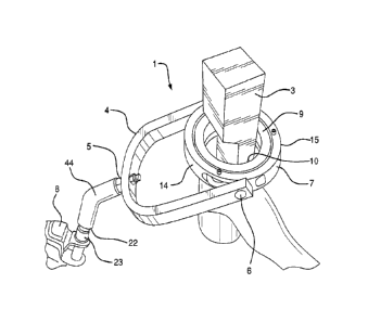
FIG. 9 depicts a gimbal assembly 108 according to an illustrative
embodiment of the invention wherein an alternative to pivot-mounting 'ears' 31
(shown in
FIG. 7) is provided. In both instances the pivot mounting ears offset the
outer gimbal
portion pivot locations from the plane of the outer gimbal portion. The pivot
ears 102,
shown in FIG. 9 however, include an adjustment mechanism to vary the position
of the tool
holder with respect to the yoke. The mechanism shown in FIG. 9 includes
threaded
members 104 attached to blocks 106. Blocks 106 are disposed on opposite sides
of gimbal
assembly 108. Threaded members 104 can be lengthened or shortened by rotating
them
with respect to blocks 106. Threaded members 104 are pivotally attached to
yoke 112 at
pivot locations 114. In this particular embodiment of the invention, threaded
members 104
are inserted into blocks 106 and adjusted to the desired length. Blocks 106
are then
attached to gimbal assembly 108 by screws 110. The particular embodiment of
the
invention shown in FIG. 9 has axle mounting locations 116 (partially shown) on
blocks 106
to allow gimbal assembly 108 to be disposed within yoke 112 such that the
pivot axis
extends through outer gimbal portion 118, rather than it being offset using
threaded
members 104. Other mechanisms for displacing outer gimbal portion 118 away
from the
pivot axis are within the scope of the invention. For example, telescoping
mechanisms with
appropriate stops and locking mechanisms can be used.
FIG. 9 also depicts yoke arm extension members 120. Yoke arm extension
members 120 function in a similar manner to threaded members 104, and also can
be
substituted with other extension mechanisms such as telescoping extensions.
The offsets
provided by threaded members 104 and extension members 120 can facilitate
installation
and use of tools of sizes and shapes that are not compatible with the non-
extended yoke
arms or the gimbal assembly in its non-offsetted position.
FIG. 9 also depicts a yoke mounting mechanism 122 having a first end
attached to yoke 112 and a second end attached to an articulating arm or part
intermediate
thereto. Yoke mounting mechanism 122 comprises two attachment parts 124, 126
which
either separate completely from one another or are hinged together, so they
can be
11
CA 02699293 2015-04-14
WO 2009/039047 PCT/US2008/076331
positioned to encircle the top bar 128 of yoke 112. A screw 130 or other
fastener secures
yoke mounting mechanism 122 to yoke 112. It is also possible for yoke mounting
mechanism 112 to slide on to yoke top bar 128. Yoke mounting mechanism 112
optionally
pivots at location 132. If no pivot is provided on yoke mounting mechanism
112, the yoke
can be pivotally connected to an articulating arm or intermediate component to
obtain an
analogous degree of freedom.
A number of embodiments of the invention will now be generally described.
In illustrative embodiments of the invention, the support and orienting
apparatus will
comprise a tool holder (such as inner gimbal portion 9) to secure the tool
within the
apparatus. To provide freedom of movement of the tool analogous to arm and
wrist rotation
for example, the secured tool will rotate within an outer component (such as
outer gimbal
portion 7). The inner and outer gimbal portions each have a rotation component
complementary to one another that allows or facilitates the inner gimbal
portion rotating
within the outer gimbal portion. An example of complementary rotation
components are
inner gimbal portion race 19 ("first rotation component") and outer gimbal
portion wheels
16 ("second rotation component"). The receptacles are preferably designed to
facilitate
removal or replacement of tools or tool components. Various configurations can
be used to
accomplish this, such as the arcuate segmenting shown in the figures (for
example major
and minor segments 14 and 15, respectively). The number of segments and the
means for
attaching them to one another can vary, provided they withstand the
anticipated application
of the device. Quick release, or hand-removable attachment mechanisms lend
themselves
well to the goal of easy tool replacement. As shown in FIG. 4a, for example,
segments of
the outer gimbal portion can be hinged. Hinging can also be used for the inner
gimbal
portion.
To secure the tool in the inner gimbal portion the inner gimbal portion will
have a tool grasping mechanism such as set crews or clamps.
The inner and outer gimbal portion combination can pivot on a yoke such as
part 4 in the figures. The shape of the yoke can vary from the U-shape shown
in the
diagrams, for example for particular types of tools or applications. The
primary function of
the yoke structure is to support the gimbal portions and provide a frame for
an additional
axis of rotation. In the illustrative figures, the inner gimbal portion has an
axis of rotation
12
CA 02699293 2015-04-14
WO 2009/039047 PCT/US2008/076331
with respect to the outer gimbal portion that is substantially perpendicular
to the axis of
rotation of the outer gimbal portion with respect to the yoke.
The yoke is preferably pivotally connected to a yoke support (such as part
44 in FIG. lb). It is noted that the yoke support can be pivotally connected
directly to the
outer gimbal portion, thereby eliminating the U-shaped portion of the yoke
structure. This
removes the degree of freedom provided by the pivotal connection between the
yoke and
yoke support, however that degree of freedom can be created by additional
pivoting
components.
The yoke support can be pivotally attached to a support arm, such as
articulated arm 8.
Turning back to FIG. la, support arm 8 and other articulated arms will be
described in more detail. The lifting structure or arm attached to embodiments
of the
inventive gimbal assembly comprises for example, a double section
parallelogram spring
arm, with preferably reduced friction joints, including, starting at the
proximal end: a hinge
with one or more vertical pivots, a first parallelogram segment with four
horizontal pivots, a
central hinge with one or more vertical pivots, a distal parallelogram segment
with four
horizontal pivots and a distal vertical pivot. A single parallelogram arm may
also be used.
Various other hinges, pivots and fastening components may also be employed.
Various spring powered 'equipoising' parallelogram arms, such as those
employed to support and position objects such as lamps, x-ray machines and
dental
equipment, can be employed in embodiments of the invention. These arms rely to
a greater or
lesser extent on friction to retain a selected angle or position, but do not
necessarily provide
consistent lift throughout the entire angular excursion of the parallelogram
links. Arms
having consistent lift can be particularly useful for many applications of
embodiments of the
invention. Iso-elastic arms that will be particularly suitable for use in
illustrative
embodiments of the invention are those with consistent lifting performance,
wherein the
fixed weight of the object being lifted is supported throughout the vertical
range of
articulation with nearly constant buoyancy.
13
CA 02699293 2015-04-14
WO 2009/039047 PCT/US2008/076331
Arms with single-spring geometries employing cams or cranks to
dynamically improve lifting consistency and range of parallelogram
articulation are
suitable for use with the invention.
Arms are tensioned, for example with springs, and can be adjustable.
'Biased hinges' may further improve arm performance by helping to
maintain the selected lateral position of the arm segments (which is termed
'centering').
Equipoising arms, such as those described in the patents/applications
mentioned above can provide the desired iso-elasticity and lateral and
vertical range.
Features, such as knob-adjusted payload adjustment to float the range of human
arm
weights from the lightest to the heaviest, and analogous 'shoulder, upper arm,
elbow and
forearm' segments can be advantageous to illustrative embodiments of the
invention.
A parking device can be incorporated, which may be either electrically or
mechanically activated, to permit a tool to be parked in a convenient stable
position when
not in use. Such devices can include for example, mechanical docking
components or
magnetic or electromagnetic devices. In an illustrative embodiment of the
invention, a hook
and mating eye permits immobilizing the entire support arm at a convenient
position and
height by, for example, swinging over to that position and permitting the hook
to rise into
the receiving eye. The operator can then open the gimbal gate and remove the
tool in order
to exchange it with another tool or perform other work with the tool that may
preclude or
does not require gimbaled support.
Combinations and permutations of any of the features described herein or
their equivalents are within the scope of the invention.
Embodiments of the invention also include a method of using a support and
orienting apparatus. The method comprises: (1) securing a tool in an inner
gimbal portion;
14
CA 02699293 2015-04-14
. .
WO 2009/039047
PCT/US2008/076331
(2) securing the inner gimbal portion to an outer gimbal portion, such that
the inner gimbal
portion rotates within the outer gimbal portion; and (3) attaching the inner
and outer gimbal
portion combination either directly or indirectly to an articulating arm. The
method can
further include using the tool to accomplish a task.
A further illustrative embodiment of the invention includes a plurality of
tools, each secured in an inner gimbal portion, configured to be inserted into
an outer
gimbal portion that is a part of a pivoting and articulating support system.
The invention
further includes a system comprising the plurality of tools, each in an inner
gimbal portion,
an outer gimbal portion, the outer gimbal portion secured to a frame that can
be pivotally
attached to an articulated arm. The system can further include the arm.