Note: Descriptions are shown in the official language in which they were submitted.
CA 02699336 2010-03-11
Method for determining the position of an intraoral measuring device
The invention relates to a method for determining the position of a measuring
device
performing measurements intraorally, which is to be moved relative to the
craniomandibular system of a patient and which measures positions within the
craniomandibular system or regions of the craniomandibular system, whereby the
position of the measuring device is measured by means of a position finding
sensor
that is in a stationary position relative to the measuring device. The
invention further
relates to a method and arrangements for evaluating and measuring the position
and pocket depth of periodontal pockets.
Known from EP-A-1 733 693 (Goldbach) is a medical tracking system with
infrared-
based operation. However, just like other systems (e.g. EP-A-1 523 950
(Foley)), it
requires an additional stand with infrared receivers and transmitters in the
operating
room for referencing. These systems link data from imaging systems with the
positional information of the navigation system for positioning instruments
for
stereotactic surgery, e.g. in neurosurgery.
There are first published reports on the use in dentistry of the above-
mentioned
systems for implant positioning (Mischkowski at al: Comparison of static and
dynamic computer-assisted guidance methods in implantology, in Int. J. Comput.
Dent. 2006 Jan; 9(1): 23-35). Here as well, image data is linked with
navigational
data in order to define the drilling direction for the implant.
CA 02699336 2010-03-11
WO 2009/034157 2 PCT/EP2008/062116
Marmulla R, at al: Intraoperative precision of mechanical, electromagnetic,
infrared
and laser-guided navigation Systems in computer-assisted surgery, in Mund
Kiefer
Gesichtschirurgie, 1998 May; 2 Suppl. 1; pages 145-8, describes the use of a
navigation system operating on an electromagnetic basis. However, there have
been
critical comments regarding the lack of precision of the results in the
presence of
metallic objects.
During intraoral scanning of teeth, the visible portion of a tooth or jaw
section, from
which 3D data is to be measured, is usually much smaller than the entire tooth
or
jaw, making it necessary to combine several images from different viewing
directions
to create a complete data set of the tooth or jaw region.
The difficulty of precisely determining the positions of regions of the
craniomandibular system, i.e. mandible and maxilla, teeth, as well as other
interesting regions such as pockets, has its roots in the fact that not only
do maxilla
and mandible move relative to each other, but the hand-guided scanner moves
relative to the jaw and the patient's head is in motion as well. In addition,
images of
jaw regions are recorded from various angles and viewpoints so that errors can
not
be ruled out even when employing mature merging software.
Even state-of-the-art software-based fitting-together or merging of individual
images
is complicated by the fact that teeth do not possess precisely defined corners
and
edges. If furthermore the positional relation of the pictures relative to each
other
(camera position) is not known, the computational effort can be quite
significant, e.g.
noticeably longer than 30 minutes for the Intraoral Scanning System of the
firm
CaDent, since the algorithms converge only slowly in the case of completely
unknown camera position and uncooperative dental geometries.
The evaluation of the electronic impression and the decision, whether the
process
may have to be repeated, result in unacceptably long waiting times for both
the
dental professional and the patient.
CA 02699336 2010-03-11
WO 2009/034157 3 PCT/EP2008/062116
In order to circumvent this problem, reference objects may be introduced into
the
mouth (US-B-7,065,243). During the intraoral measuring of one or several teeth
in
the presence of a reference, the reference pinpoints the position of a camera
that is
used to measure the tooth or teeth. Once the camera position relative to the
tooth or
teeth is known, the measurements are used to generate a 3D model that is
needed
for the manufacture of dental prostheses. A method of this type is complicated
and
in addition has the disadvantage that the reference is embodied as an open
cuboid
box that casts shadows onto the tooth or teeth.
US-A-2003/0219148 also relates to a method for generating a three-dimensional
model of a dental arch with the aid of three-dimensional referencing.
A method for intraoral scanning is also known from US-A-2006/0212260. Used for
this is a scanner that comprises an inertial or tracking system to determine
orientation and position.
An intraoral measuring system according to US-A-2005/0020910 features the
option
of integrating both a scanner as well as a receiver attached to the patient's
head
with a three-dimensional tracking system.
DE-B-100 45 381 relates to a device for determining the position of a medical
instrument, or apparatus, or body part. For this purpose, the object whose
position
is to be determined is equipped with active and passive reference bodies, so
that a
navigational system can determine the position. In this, it is possible to
employ
inclination-measuring as well as magnetic-field sensors.
Disclosed in EP-A-1 088 525 are a method and a device for aligning medical
images
on a patient. Provided for this purpose are holder elements, which can be
connected
to the patient's body and are equipped with marking or localizing means. The
purpose is to provide a three-dimensional localizing system
CA 02699336 2010-03-11
WO 2009/034157 4 PCT/EP2008/062116
for computer-assisted surgery, in order to facilitate the alignment relative
to medical
surgical procedures.
State of the art measurements of the depth of periodontal pockets or for the
diagnostic of dental caries do not use any augmentation with positional data.
Consequently, automatic processes for transmitting the measured data into the
patient management system of the dental clinic are not possible.
Today's work in diagnosing periodontal diseases is performed by inserting the
measuring probe manually into the gingival pocket and by reading a scale on
the
probe to determine the depth. From the location of the measuring, the doctor
communicates a value to the assistant, who then records the corresponding data
in
dependence on the tooth or position of the measurement relative to a tooth.
This
entails high costs in both time and personnel.
In the diagnostics of dental caries as well, the diagnosis including the tooth
position
is verbally transmitted or is entered into the clinic's computer by the
treatment
professional him/herself. Not only does this entail a great deal of lost time,
but there
are also hygienic concerns, since while working on a patient one also has to
operate
a keyboard, which is hard to maintain in a sufficiently sterile state.
Known in the art is only one electromechanical apparatus for determining the
pocket
depth, which however does not determine any positional data (Florida probe;
www.floridaprobe.de). The pocket depth is determined by a mechanical back
stop,
through which the pin-shaped probe slides until it touches the bottom of the
pocket.
The path traveled by the pin on its way to the pocket bottom is converted to
an
electrical signal dependent on a change in opening angle of a mechanical
expansion
device and is then transmitted to a PC. At least in case of the Florida probe,
PC
speech input reduces the risk of contamination from the keyboard.
Disclosed in DE-A-37 12 054 is a measuring probe for acquiring the depth of
gingival pockets. Also employed in this can be inductive or optical detecting
elements, which also include the use of light guides.
CA 02699336 2010-03-11
In accordance with US-A-5,100318, the depth of the gingival pockets is
measured by
means of ultrasound. The same is true for US-A-5,755,571, which proposes an
ultrasound measuring apparatus to measure the pocket depth. Also provided is
the
option of measuring the position of the tip of the measuring device relative
to the pocket
by means of a sensor.
Described in DE-C-38 36 743 is a capacitive measuring method for determining
the
accuracy-of-fit of dental prostheses such as crowns and bridges.
For the purpose of determining the distance between a crown and the tip of a
dental
root, DE-A-198 54 223 proposes a device that is used to generate first and
second
measuring signals, from which the position is determined.
Described in US-A-4,673,352 is a device for measuring the position and
movement of a
patient's mandible relative to the maxilla. For this purpose receivers that
are arranged
stationary on the patient's head receive ultrasound signals emitted by a
measuring
device.
For the purpose of acquiring the position surgical instrument, US-B-6,381,485
provides a
reference sensor at the patient's head. A magnetic field sensor is located on
the
surgical instrument.
In order to represent/display a jaw, it is necessary in accordance with EP-A-O
741 994 to
first introduce into a patient's oral cavity a device for position finding,
which is equipped
with markings or reference points. Connected to the device is a sensor. A
further sensor
originates from the patient's mandible.
EP-A-O 951 874 discloses a system for position finding by means of a reference
unit
attached to the head of a patient. For this purpose one attaches to a
patient's head a
headset containing a reference unit that is connected to a position-finding
unit via a
communication line.
AMENI)ED PAGE
CA 02699336 2011-10-04
6
The present invention is based on the objective to further develop a method
for
determining the position of a first sensor, which is movable relative to a
patient's
craniomandibular system and which is used to measure positions in the
craniomandibular system or regions of the craniomandibular system,
particularly
positions at or of teeth and/or regions of gingival pockets, in a manner so as
to eliminate
the need for any referencing systems existing independent of the patient, in
particular a
referencing system to be mounted on a stand in the treatment room. The method
also
should be insensitive to metals in the oral cavity. Furthermore, in comparison
to state-
of-technology solutions, the data amount to be processed is to be reduced
without any
accompanying decrease in accuracy. The measurements should be safe from
falsification due to movement of the patient during the measurements.
When employing an intraoral scanner as a sensor, the combining of partial
measurement data into a consistent 3D data set is to be accelerated by
providing
coarse positional data.
A further objective is to facilitate preferably fully automatic data
acquisition during
pocket-depth measurements and/or the detection of dental caries or plaque,
particularly
if a starting position of the measurements is known.
In accordance with the invention, at least some aspects of the above-described
problem
are overcome by using an inertial platform as the position finding sensor and
determining the positional data of the measuring device by additionally taking
into
account at least one second position finding sensor arranged in stationary
relation to the
maxilla of the craniomandibular system, and by evaluating the positional data
of the two
position finding sensors synchronously after the triggering of a starting
signal.
In accordance with a proposed independent solution, the invention intends that
as the
position finding sensor is used an inertial platform and that the
determination of the
position of the measuring device by means of the position finding sensor be
performed
in relation to a starting signal chosen as a starting point. The starting
signal may be of a
spatial nature, i.e. possess a stationary location relative to the
craniomandibular system.
CA 02699336 2011-10-04
6a
Starting from a first determination of position, which for example may take
place at a set
starting point as a reference point, one subsequently determines changes in
the
positional data of the measuring device by means of further measurements
spaced over
time.
In this, the changes in position of the measuring device are determined by
means of an
inertial platform, which is present or integrated in - or has a known spatial
relation to -
the measuring device. Measured are three degrees of freedom of translation and
three
degrees of freedom of rotation, which enables one to pinpoint the change in
location of
the scanning sensor relative to the craniomandibular system of the patient.
Preferably,
the change in position takes place taking into account data of a second
inertial platform,
which is arranged in a stationary location relative to the maxilla.
According to the invention, the new position relative to the first measurement
is
computed by integrating the movement changes. Any tilting in space can be
measured
directly, if necessary.
In this, the invention's solution does not operate by incorporating data that
has been
obtained by means of imaging processes, but rather is able to create three-
dimensional
imaging data on its own.
CA 02699336 2010-03-11
WO 2009/034157 7 PCT/EP2008/062116
The use of an inertial platform can involve disadvantages related to temporal
drift,
which is also known in gyro systems in aviation. This on principle requires
from time
to time a re-calibration to a fixed coordinate system. However, within the
short
measuring periods involved in recording the 3D data of the craniomandibular
system, this drift is so small that corrections are not really necessary.
For measurements in which patient movements can be assumed to be negligible in
comparison to the position of the measuring device or sensor, the inertial
platform in
the measuring device is sufficient.
For when patient movements are not negligible, the invention intends that the
further
position finding sensor (inertial platform) on the patient's head, i.e. in a
stationary
location relative to the maxilla of the craniomandibular system, be used to
measure
the movement that took place during the measuring period. Thus the patient's
head
movement can be measured separately from the actual movement of the measuring
device.
For this purpose, a frame such as a spectacle frame may be used. It is also
possible
to use a facebow for mounting the second sensor. Alternatively, a bite fork
with an
inertial platform may be attached to the maxilla or mandible.
Another option is that a bite block, which contains the at least one second
inertial
platform, is placed between the dental rows and the patient is requested to
close the
dental rows.
It is particularly intended that the positional data of the first position
finding sensor,
i.e. first sensor (inertial platform), be linked as first coordinates with
second
coordinates represented by the positional data of the optional at least one
second
position finding sensor, i.e. second sensor (inertial platform), and that the
linked
coordinate data be used to generate coordinates for the first sensor and the
at least
one
CA 02699336 2010-03-11
WO 2009/034157 8 PCT/EP2008/062116
second sensor in a common coordinate system, in which the coordinates of
positions or regions of the craniomandibular system are determined.
For measurements at the mandible it is preferable to attach one further
inertial
platform in a location stationary relative to the mandible. This for example
can be
accomplished using a bite block or a bite fork attached to the mandible.
Unfavorable
space conditions may make it necessary in clinical application to do without a
stationary positioning relative to the mandible of the at least one inertial
platform.
This is practicable if determining a position within the chewing plane is
sufficient. In
this case it is possible to assume, taking into account the movement of the
mandible
relative to the maxilla, that the mandible moves relative to the maxilla along
an arc-
shaped path of motion that is governed by the temporomandibular joint.
Measuring a
measuring point, e.g. between teeth 31 and 41 during the opening motion of the
mandible reveals the motion of the mandible. Every other point of the mandible
will
travel on a similar - in the mathematical sense - curve. Further, one can take
into
account a typical mouth opening size to perform an additional rough estimate.
To a first approximation, the position of a gingival pocket will always travel
on the
same arched path.
Because of the inertial platform that is fixed to the measuring device
(intraoral
scanner) and provides position-change data (either without or much more
precisely
with a further inertial platform arranged stationary relative to the maxilla),
one knows
the current rough position of the scanning sensor relative to the
craniomandibular
system and the positional change relative to earlier positions. This makes it
possible
to speed up the merging of individual 3D data sets or, in some cases with
difficult
geometry, to make it possible at all, since the employed algorithms have
difficulties
in particular in the rough determination of the relative positions of two or
more
individual data sets. If the rough position is known, the following fine-
adjustment of
the data sets relative to each other
CA 02699336 2010-03-11
WO 2009/034157 9 PCT/EP2008/062116
can be accomplished much simpler and faster, so that the scan results can be
linked
with relatively low computational effort.
The invention makes available an intraoral scanning system that comprises a
device
for determining rough positions and the changes in these positions relative to
the
craniomandibular system.
In accordance with an independently inventive suggestion, the intraoral
measuring
device is not only used for scanning a dental arch or a section thereof - in
order to
determine the position of teeth or regions that are to be provided with dental
reconstructions -, but also to measure the depth of gingival pockets or the
position
and extent of dental caries or plaque.
The latter is of importance particularly if it is intended for example to
measure
gingival pockets, i.e. their depth, without the usual recording of data by
calling out
the measuring points. Rather, if the starting position of a gingival pocket or
region of
a gingival pocket of a tooth is known, measurements of regions of the gingival
pocket of the same tooth and adjacent teeth can subsequently be performed
automatically and consequently recorded, since the location of the resulting
positional coordinates is determined from the position of the measuring
device, i.e.
the first sensor (inertial platform), in relation to the at least one second
sensor
arranged stationary relative to the maxilla.
In accordance with the invention this can be performed fully-automatically or
semi-
automatically. If a pocket-depth-measuring section of the measuring instrument
is
pushed into the pocket, then owing to the teaching according to the invention,
the
position of the measuring device can be determined and recorded automatically.
During semi-automatic measuring it will only be necessary to take a reading of
the
pocket depth on the measuring device (e.g. on the scale of a probe extending
from
the measuring device) and to transmit the reading to the patient documentation
software on the PC, e.g. by means of a voice-recognition system. The position
of
the measuring device itself is acquired automatically. In order to facilitate
automatic
position finding, a starting position must be specified, e.g. contact with the
gingiva
approximal between teeth 31 and 41. Once this position is known,
CA 02699336 2010-03-11
WO 2009/034157 10 PCT/EP2008/062116
then owing to the teaching according to the invention, during any movement of
the
measuring device the new position is determined automatically relative to the
first
position, so that the position of each measuring point can be acquired
automatically.
As mentioned above, in the semi-automatic acquisition it is only necessary to
enter
the pocket depth into a computer for each measurement, e.g. via a computer
keyboard or voice-recognition software, while the position itself is stored
automatically.
In addition to automatically determining the position of the measuring
location, the
measuring process itself can also be performed automatically without the need
to
read off data. This as well is to be seen as an independently inventive
suggestion.
This can be accomplished in various ways, e.g. using a drag indicator with an
electronic read-out (e.g. Florida probe), or pocket-depth measurements using
ultrasound, or opto-electronic or impedance-change methods.
Measurements obtained with a method of this type can then be stored
automatically
together with the positional information in a patient management system.
In particular, the measuring of pocket depths is performed by means of an
optical
light guide, in the form of one or several fibers of a material transparent to
electromagnetic radiation, e.g. glass, sapphire, or plastic, which is inserted
into the
pocket. The diameter of the optical light guide may be in the region of
between 50
pm and 1000 pm without this restricting the teaching of the invention. As soon
as
the optical light guide penetrates into the pocket, the light intensity and
spectral
distribution of the light, which is collected by the light guide along its
front face and is
transmitted to a receiver, are modified by the optical characteristics of the
gingiva
and the tooth. From this one can determine the penetration depth of the tip of
the
light guide into the pocket, whereby the measurement is terminated when the
front
face of the light guide touches the bottom of the pocket. The pocket depth is
subsequently calculated as the difference between the position where entry
into the
pocket was detected and the position where no further movement along the z
direction (along the depth of the pocket) takes place.
CA 02699336 2010-03-11
WO 2009/034157 11 PCT/EP2008/062116
The light captured by the light guide may be ambient light, which is emitted
by for
example the lighting of a dentist's chair. But it is also possible to conduct
light
through the light guide itself and to measure the light reflected at the fiber
end by
means of a photodiode or another light detector.
A further option is to measure the light backscattered into the cladding of
the light
guide, or changes in that light.
According to a further proposal at least two optical guides are inserted into
the
pocket, whereby light is emitted by one or several guides and light is
received and
subsequently analyzed via at least one other guide. This increases the
detection
sensitivity of the reflected signal, and different numerical apertures, light
guide
diameters, and distances between light guides may be used to select a region
from
where the light reflected into the light guide preferably is to be received.
When using
several light guides, the spacing between light guides preferably should
correspond
to 0.5 to 3 times the light guide diameter, but need not be limited to this.
It is also possible to use a coaxial arrangement of a small light guide tube
and light
guide loosely inserted into the small tube.
According to a different proposal it is intended to use a light guide whose
cladding
and coating has been removed and whose core has been roughened. The
roughened light guide subsequently is housed in an air jacket or at least a
coating of
a material with a low refractive index x with x << 1.3. A design of this type
ensures
that the optical fiber in its roughened region has nearly isotropic emissions.
Alternatively a small rod of a scattering medium can be attached to the end of
a
fiber, which for an adequate choice of the scattering coefficient
(0.1 /mm<ps<100/mm)
CA 02699336 2010-03-11
WO 2009/034157 12 PCT/EP2008/062116
will also generate a light intensity that is most homogeneous along the length
of the
small rod.
Now one has the option of charging the fiber with light of one or several
wavelengths, by means of for example an LED, a laser diode, or another light
source. If necessary it is also possible not to illuminate the fiber, but use
it to only
pick up ambient light. Measurements of this type may be subject to errors.
If the fiber is charged with light, then this will be emitted more or less
isotropically
from the roughened end and the corresponding reflected light is gathered. As
soon
as the roughened region penetrates into the pocket, the reflection rate will
change
from that of a fiber to air reflection to that of a fiber to tissue reflection
and the
reverse case. This results in a change in intensity and spectral distribution
of the
reflected light. The degree of change corresponds to the penetration depth of
the
sensor into the gingival pocket. The sensor is active at all times and
directly detects
the penetration into the pocket. The deeper the sensor is located inside the
pocket,
the more noticeable will be a signal change.
For the purpose of increasing the sensitivity it is also possible to use two
corresponding fibers that are surrounded by air or sheathing with a very low
refractive index, whereby one fiber serves as sensor and the other fiber as
receiver
with regard to their roughened regions. Direct light transfer from the
transmitter to
the receiver is prevented by screening between the sensors. In this case the
light
guide acting as the receiver only detects light reflecting from tooth or
tissue,
whereby the reflected light will be attenuated and diffracted differently for
each
wavelength, making it possible to draw conclusions about the characteristics
of the
tissue or tooth that the light passed through or that reflected the light.
Differences
between the wavelengths increase in dependence on the penetration depth of the
fiber into the material.
CA 02699336 2010-03-11
WO 2009/034157 13 PCT/EP2008/062116
Measurements of the spectrum of the backscattered light can also be used to
determine whether the tissue or gingiva is inflamed. The perfusion of the
tissue with
blood changes in dependence on the extent of the inflammation. The optical
characteristics of blood are different from those of the tissue. The extent of
perfusion
can be determined if one uses applied light of suitable wavelengths. For
reference
one can use two components of the tissue, namely proteins and water, whereby
proteins show a noticeable absorption of wavelengths below 350 nm and water
for
those above 1500 nm. The absorption maximum of blood is at approximately 400
nm
with moderate absorption taking place in the range between 650 nm and 1000 nm.
Measuring the ratio of the reduced blood absorption in the wavelength regions
< 350
nm and > 1500 nm relative to the significant blood absorption in the
wavelength
region 400 nm to 1000 nm allows conclusions to be drawn about the blood
perfusion
in the tissue. Methods relating to this can be combined in any manner with the
determination of gingival pocket depth by means of optical fibers.
However, it is also possible to determine the pocket depth via impedance
measurements. An electrically conducting tip, such as e.g. a periodontal
probe, can
be inserted into the pocket while simultaneously measuring the resistance of
the
tissue. As soon as the tip of the probe comes into contact with crevicular
fluid, the
resistance will drop, e.g. to a value lower than 200 kS2. The resistance in
air is
greater than 1 MK 2. The penetration depth of the tip into the pocket
subsequently is
determined by moving the sensor in order to calculate the pocket depth in this
manner. Also used may be a bipolar needle that is coated with a saliva-
repellent
surface such as Teflon.
Alternatively it is possible to use a non-conducting probe body that in some
regions
is equipped with conducting annular sections at different distances from the
probe
tip. During the penetration of the probe into the pocket, one ring after
another is
covered by fluid and the impedance between the rings changes. Also feasible is
the
performance of capacitive measurements.
CA 02699336 2010-03-11
WO 2009/034157 14 PCT/EP2008/062116
It is also possible to measure the gradual immersion of the probe into the
periodontal pocket by means of layer with average or high resistance per unit
length
that is applied onto the probe. Here one uses the characteristics of a
potentiometer.
An independently inventive teaching allows determining the location or areal
extent
of dental caries or plaque by means of the first position finding sensor. In
this, one
utilizes the different reflection characteristics of dental caries or plaque
in
comparison to healthy tooth regions.
Also possible is the detection/acquisition of the movement of the mandible
relative to
the maxilla, if one position finding sensor (inertial platform) is attached to
the head of
the patient and one further position finding sensor (inertial platform) is
attached to
the mandible. In particular, this allows performing dynamic occlusion
measurements.
Further details, advantages, and features of the invention are not only found
in the
claims and the characteristic features contained therein, on their own and/or
in
combination, but also in the following description of preferred embodiment
examples
illustrated in the figures.
Figure 1 shows a schematic illustration of first and second position finding
sensors
that are aimed at a craniomandibular system,
Figure 2 shows a flow chart,
Figure 3 shows a first embodiment of an arrangement for measuring the depth of
a
gingival pocket,
Figure 4 shows a further schematic illustration of measuring sensors,
CA 02699336 2010-03-11
WO 2009/034157 15 PCT/EP2008/062116
Figure 5 shows a third embodiment for measuring the depth of a gingival
pocket,
Figure 6 shows a fourth embodiment for measuring the depth of a gingival
pocket,
Figure 7 shows a fifth embodiment for measuring the depth of a gingival
pocket,
Figure 8 shows a sixth embodiment for measuring the depth of a gingival
pocket,
and
Figure 9 shows a seventh embodiment for measuring the depth of a gingival
pocket.
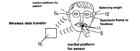
Figure 1 purely schematically shows a measuring device to be referred to as an
intraoral scanner 10, into which is integrated an inertial platform (first
sensor), which
allows detection of the position of the measuring device in dependence on its
motion
along the X, Y, and Z directions as well as rotation about the respective
axes. The
inertial platform may be based, on for example an ADIS 16355.
The position of the measuring device 10 and thus the first position finding
sensor 11
is determined relative to the position of at least one second position finding
sensor
14 by means of a computer 16, to which the data of the first position finding
sensor
and the second position finding sensor 14 are transmitted, ideally in a
wireless
fashion. The second sensor 14 also contains an inertial platform. The second
position finding sensor 14 may be integrated into the temple arms of
spectacles or in
a facebow, or into bite blocks that can be positioned between the mandible and
maxilla. A balance weight 12 is attached to the spectacle frame to realize a
symmetrical weight distribution.
CA 02699336 2010-03-11
WO 2009/034157 16 PCT/EP2008/062116
Thus the computer uses the data of the first position finding sensor 11 and
the
second position finding sensor 14 positioned stationary relative to the
maxilla to
determine the positions of the intraoral scanner, and links them with the 3D
data
measured at the respective positions. This speeds up the rough positioning of
the
individual data sets within the common coordinate system (step 20 in figure
2). After
step 20 the 3D data sets are located within a common coordinate system (step
22).
Subsequently performed are fine adjustments to find the best-possible position
of the
data sets relative to each other (step 24). The uniform 3D data set 26
obtained in this
manner now can be used in the manufacture of dental prostheses after further
known steps.
The invention's method offers significant savings in computing time, in
particular for
the digital representation of regions of the mandible and/or maxilla, and
avoids
incorrect representations, since the positions of the intraoral scanner
relative to a
region to be scanned are determined at least roughly by the inertial platforms
or
corresponding position-finding means with equivalent technical effect, which
simplifies the task of registering the partial data sets obtained at different
viewpoint
angles. This rules out incorrect assignments that would be possible with
completely
unknown scanner positions.
In accordance with the embodiment example that employs two position finding
sensors, the first position finding sensor transmits data (acceleration
values) that are
used to compute the change in location of the measuring device relative to the
previous measuring location. The second position finding sensor transmits data
that
allow drawing conclusions on the change in position of the patient relative to
the
patient's original position.
Naturally it is still within the scope of the invention to employ only one
position finding
sensor that determines data related to the change in position between the
individual
measuring locations. This is accomplished on the basis of the data detected by
the
inertial platform,
CA 02699336 2010-03-11
WO 2009/034157 17 PCT/EP2008/062116
i.e. the recording of acceleration values, which in combination with their
progression
over time allows the computation of the resulting change in position.
On principle, no absolute positions are detected in the 6 degrees of freedom.
However, absolute positions can be determined in relation to a known starting
position.
In order to measure the depth of gingival pockets at different positions of a
tooth, the
method according to the invention, i.e. the determining of the positional
location of
the measuring device 10, can be employed using the first position finding
sensor on
its own or in combination with a or the second position finding sensor 14,
whereby a
sensor element, such as a pin or optical guide, extending from the measuring
device
10, is used to measure the pocket depth. But it is also possible to determine
the
pocket depth using ultrasound, in which case the transmitter and receiver
originate
from the sensor. The pocket depth also can be measured by means of impedance
metering.
However, the measurement preferably is performed opto-electronically. In
accordance with figure 3, an optical guide in form of an optical fiber 28
consisting of
plastic or glass is surrounded by a light-conducting coating 30. The light
guide
subsequently is inserted into a gingival pocket 32. Light from a light emitter
such as
at least one light-emitting diode or laser diode 34 is, emitted via the light
guide 28,
and subsequently radiation reflected in the pocket 32 is guided back to the
light
sensor 36 via the fiber 28. For short distances, it is also possible to guide
the
reflected light back to a receiver via coupling into the front face 34 of the
coating 30.
This entails the advantage of spatially decoupling the light paths of the
transmitter
and receiver. At the point in time when the front face of the fiber comes into
contact
with the gingiva, i.e. enters the gingival pocket, the reflected light shows
changes in
its intensity and - if more than one wavelength is used - also its spectrum.
Consequently the time of entry into the gingival pocket is known. The movement
along the pocket direction terminates at the bottom of the pocket. The
distance
traveled
CA 02699336 2010-03-11
WO 2009/034157 18 PCT/EP2008/062116
since the time of entry corresponds to the pocket depth and can be determined
by
means of the known positional data from the inertial platform.
It is also possible to insert two optical guides 38, 40 side by side into a
pocket,
whereby light is introduced via one guide, e.g. the optical guide 38, so that
the
optical guide or fiber 40 can gather radiation reflected in the pocket, or by
the tissue,
or by the tooth bordering the pocket, and feed it to a receiver for
interpretation. The
separation d between the guides 38, 40 should preferably be 0.5 to 3.0 times
as
large as the diameter of each guide 38, 40.
As illustrated in figure 5 it is also possible to use a coaxial embodiment. A
light guide
42 is positioned inside a small tube 40 of glass, sapphire, or quartz so that
it is not in
contact with the interior surface of the small glass tube. As soon as the
assembly
comes into contact with the gingiva or is immersed into the gingival pocket,
the
intensity and spectral distribution of the light guided back through the
material of the
small tube will change. To prevent liquid from penetrating into the air gap
40a, the
assembly is sealed with a transparent window of the same material as the
material
of the small tube.
The embodiment example shown in figure 6 employs a light guide 44 that is
roughened in its end region 46. For this purpose both the cladding 48 as well
as the
coating 50 of the light guide are removed. The roughened end region 46
subsequently is arranged inside an enveloping element 50a and is arranged with
clearance to its inner surface, whereby the space in between is filled with
air. This
results in a sudden change in the refractive index, which allows a nearly
uniform
light emission. Instead of using an enveloping element 50a with air gap it is
also
possible to coat the roughened section 46, for example with a material having
a low
refractive index such as Teflon.
The roughened region offers the advantage of nearly isotropic emission of
light and
of nearly isotropic gathering of reflected light. As soon as the roughened
region is
pushed into the pocket, the optical characteristics of the periodontal tissue
traversed
by the light will change the amount and spectral distribution
CA 02699336 2010-03-11
WO 2009/034157 19 PCT/EP2008/062116
of the backscattered light in dependence on the penetration depth into the
periodontal pocket.
In this manner it is not only possible to determine the pocket depth, but also
to detect
possible inflammation of the gingiva. For this purpose the light guide is
charged with
radiation of a wavelength region in which the components characterizing the
tissue,
i.e. protein and water or blood, absorb the radiation to a particularly high
degree.
Subsequently, ratios of intensities in characteristic absorption regions are
compared
to infer results on the type and extent of the inflammation.
Figure 7 illustrates an embodiment version in which - in accordance with
figure 6 - a
light guide 54, which has been stripped of coating and cladding at its
roughened
end, guides and emits radiation into the region of interest to be measured and
a light
guide 56 prepared in the same manner gathers radiation reflected from the
region
and feeds it to a receiver. In this the active, i.e. roughened, regions of the
light
guides 54, 56 should be optically separated or shadowed. Because of this
screening, the light must travel a further distance through the tissue.
Consequently
this arrangement becomes more sensitive to variations in the optical
characteristics
of the tissue and to the penetration depth into the gingival pocket.
It is also possible to perform measurements of impedance to determine the
pocket
depth. For this one can employ a conducting tip, such as the tip of a
periodontal
probe, with impedance that varies in dependence on contact with crevicular
fluid.
When the tip is not in contact with fluid but rather moves through air, the
resistance
will be greater than 1 M. At the very moment that contact is established with
the
fluid in the gingival pocket, the resistance drops to values of less than 200
kQ. This
change in resistance is used as an indicator of penetration into the pocket.
Subsequently the tip is moved into the pocket and all the way to the bottom
and the
shifting distance is determined by means of the first sensor equipped with the
inertial
platform, in order to automatically determine the depth. The end point is
considered
reached when the motion into the pocket stops.
CA 02699336 2010-03-11
WO 2009/034157 20 PCT/EP2008/062116
Another option is to insert into the pocket a tip that is equipped with
electrodes in
planes that extend in parallel and are electrically insulated relative to each
other,
whereby the tissue and the fluid present in the pocket will create an
electrically
conducting connection between the electrodes. A corresponding design is shown
in
figure 8. Around a conducting core 60 are grouped alternating insulation
layers 59
and conducting layer 62. This creates conductive annuli, each of which is
equipped
with its own pad electrode 61. If the insulation layer between the electrodes
is wetted
by a conductive fluid or if tissue comes into contact with two neighboring
electrodes,
the resistance between these two electrodes drops significantly, allowing a
stepwise
measurement of the penetration depth of the probe into a fluid or into the
periodontal
pocket. A practical design version can resolve changes in penetration depth of
0.5
mm - 1 mm. In order to be able to perform a depth measurement, the free ends
of
the conducting core 60 or the conducting layers terminate in different planes,
as is
indicated in the figure.
Pockets can also be measured by way of a capacitive measurement. For this
purpose two or more electrodes 64 are arranged on opposite sides of a small
carrier
rod 63 of a material having a low dielectric coefficient, e.g. Teflon or
polypropylene,
which in combination with the tissue that the probe is immersed in form a
capacitor.
The electrodes 64 are coated by a preferably hydrophobic insulating layer and
are
connected to evaluation electronics via connecting leads 67. The capacitance
of the
assembly changes in dependence on the immersion depth 65.
If - as in the embodiment version according to figure 9 - the insulation 66 is
removed and the electrodes 64 are produced from a medium to high resistance
material it is possible to determine the immersion depth from the continuous
change
in resistance of the assembly.
The intraoral scanner 10 not only can be used to automatically determine
positions
in the craniomandibular system or regions of the craniomandibular system, such
as
local arrangements of teeth or measuring points with simultaneous depth
measurement of a gingival pocket, but it is also possible to determine the
position
and extent of dental caries or plaque. For this one utilizes the difference in
reflection
spectra of a healthy
CA 02699336 2010-03-11
WO 2009/034157 21 PCT/EP2008/062116
tooth compared to regions affected by caries or plaque, which can be evaluated
together with the position finding of the first sensor.