Note: Descriptions are shown in the official language in which they were submitted.
CA 02699436 2012-03-20
CA 02699436 2010-04-08
1
HEATING AND COOLING UNIT., AND HEATING AND COOLING
APPARATUS
BACKGROUND
1. Technical Field
The present invention relates to a heating and cooling unit
and a heating and cooling apparatus for adjusting the temperature
of feed air to be fed and supplying air to the room inside.
2. Description of Related Art
A heating and cooling apparatus for carrying out comfortable
heating and cooling by, for example, burying a heating and cooling
unit provided with a radiation panel, in which a plurality of pipes for
letting heating medium or cooling medium through are installed, in
CA 02699436 2010-04-08
2
the ceiling and carrying out radiation heating or radiation cooling is
in widespread use instead of a conventional heating and cooling
apparatus (e.g., a multi air conditioner or a fan coil unit) for blowing
cold air or warm air directly to the room inside.
For example, disclosed in Patent Literature 1 is a ceiling
heating-cooling radiation panel comprising: a pipe support part,
which is formed to be integrated with a radiation panel body and in
which a pipe for letting temperature medium through can be fitted
from the thickness direction of the radiation panel body; and a pipe
screw member, which is engaged with the pipe support part to fix
the pipe for letting temperature medium through, whereby
attachment of the pipe for letting temperature medium through can
be facilitated and replacement of the pipe for letting temperature
medium through can be carried out easily even after installation
thereof. (refer to Japanese Patent Application Laid-Open No.
H7-19533 (1995)).
SUMMARY
On the other hand, a heating and cooling apparatus such as a
multi air conditioner or a fan coil unit described above has a problem
that the wind velocity of cold air or warm air from an indoor
equipment installed at the room inside is too high, and causes the
user of the room inside to feel a draft and tends to cause
temperature unevenness at the room inside.
Moreover, the air conditioning efficiency of the heating and
CA 02699436 2010-04-08I
3
cooling apparatus described above, which uses radiation cooling or
radiation heating, is low since only low heat or high heat due to
radiation cooling or radiation heating is employed therein, and the
range of use of the heating and cooling apparatus is limited. For
example, it is not appropriate to use the heating and cooling
apparatus in a place having poor thermal insulation properties, a
place having a large thermal load, or a place having much air
flowing into and out thereof. Moreover, there is another problem
that it is necessary to provide measures against dew condensation or
the like separately, which causes cost increase.
However, the ceiling heating-cooling radiation panel of the
Patent Literature 1 cannot resolve the above problems.
The present invention has been made in view of such a
situation, and an object thereof is to provide a heating and cooling
unit and a heating and cooling apparatus in which since supplying
mixed air which is obtained by mixing feed air to be fed and
circulated air from the room inside, to the room inside in a laminar
manner, and emitting heat obtaining from the mixed air, to the room
inside so as to carry out an air conditioning of the room inside, it
becomes to possible to get high efficiency and high power, to reduce a
space unsuitable for air conditioning than air conditioning by the
conventional radiation panel employing only heat emission, to
prevent a draft and temperature unevenness, to expand the range of
usage of the apparatus, and to avoid the need of a measures against
dew condensation.
CA 02699436 2010-04-08 1
4
A heating and cooling unit according to the present invention
is characterized by comprising: a mixer case for supplying mixed air,
which is obtained by mixing circulated air from the room inside with
feed air to be fed, to the room inside; a guide path, which is
communicatively connected with the circulated air, for guiding the
feed air to the mixer case; and a heat storage radiation member,
which is attached in the mixer case in a thermally-conductive
manner, for obtaining heat from the mixed air and radiating the
heat to the room inside.
In the present invention, feed air to be fed is blown through
the guide path to the mixer case. In such a manner, the circulated
air flows through the guide path into the mixer case and is mixed
with the feed air to become mixed air. The heat storage radiation
member obtains low heat or high heat from the mixed air and carries
out radiation cooling or radiation heating to the room inside.
A heating and cooling unit according to the present invention
is characterized by comprising: an adjustment case for adjusting the
flow of the feed air; and a box member, which has an opening at one
face thereof and is buried in a wall at the room inside with said one
face facing the room inside, for housing the adjustment case, the
mixer case and the guide path, wherein a circulated air path
communicatively connecting from the opening to the guide path is
formed inside said box member.
In the present invention, the box member houses therein the
CA 02699436 2010-04-08 I
5
adjustment case, the mixer case and the guide path, and the
circulated air path is further formed. Circulated air enters the box
member via the opening, travels through the circulated air path and
the guide path, and flows into the mixer case.
A heating and cooling unit according to the present invention
is characterized in that the heat storage radiation member
comprises a plurality of juxtaposed flow dividing fins for dividing the
flow of mixed air to be supplied to the room inside and letting the
mixed air through.
In the present invention, the flow of mixed air to be supplied
to the room inside is divided into a plurality of layers by the flow
dividing fins of the heat storage radiation member, and the mixed
air is supplied to the room inside in a so-called multi-layer flow
manner, and therefore the draft to be given to the user of the room
inside is suppressed.
A heating and cooling unit according to the present invention
is characterized in that the heat storage radiation member
comprises an elliptical heat storage pipe penetrating the plurality of
flow dividing fins in a juxtaposition direction of the flow dividing
fins.
In the present invention, since the heat storage pipe has an
elliptical shape, a pressure loss to be caused by collision between the
mixed air and the heat storage pipe while the mixed air passes the
heat storage radiation member and is fed to the room inside can be
reduced, and the mixed air passes the heat storage radiation
CA 02699436 2010-04-08
6
member smoothly and is supplied to the room inside. Moreover, the
heat storage pipe strengthens the flow dividing fins and radiates
heat, which is obtained from the mixed air and stored, to the room
inside.
A heating and cooling unit according to the present invention
is characterized by comprising a plurality of short tubular
protrusions, which are formed to protrude from a face of the flow
dividing fins, for changing the direction of radiation heating toward
the room inside and dividing the flow of the mixed air.
In the present invention, the short tubular protrusions
change the direction of radiation heating toward the room inside and
further divide the flow of mixed air to be supplied to the room inside.
Moreover, since the protrusions come into contact with the mixed air
at this time, heat is obtained from the mixed air and transferred not
only by the flow dividing fins but also by the protrusions more
uniformly over the entire area of the heat storage radiation member,
and occurrence of temperature unevenness in radiation heating to
the room inside and in supply of mixed air is inhibited.
A heating and cooling unit according to the present invention
is characterized in that the protrusions are juxtaposed in the
longitudinal direction of the flow dividing fins so as to reach or
almost reach adjacent flow dividing fins, the mixer case comprises
an aperture face, which has an aperture where mixed air to be
supplied to the room inside passes and faces said room inside, and
the aperture is positioned below the protrusions.
CA 02699436 2010-04-08 I
7
In the present invention, the flow of mixed air in the mixer
case is divided by the protrusions and the mixed air passes the
aperture of the aperture face positioned below the protrusions and
enters the room inside through the opening. Moreover, the
direction of radiation heat from the mixed air is changed by the
protrusions and the radiation heat passes the aperture of the
aperture face and enters the room inside through the opening.
A heating and cooling unit according to the present invention
is characterized in that the box member has a flat shape, the mixer
case has a flat box shape, the circulated air path is formed at the
outer side of one face opposed to the aperture face and the outer side
of any two opposed side faces adjacent to the aperture face, a
rectangular air suction port for suctioning adjusted air from the
adjustment case and circulated air from the room inside is provided
at the midpoint between the two opposed side faces on the one face of
the mixer case, the adjustment case comprises a rectangular air
blowoff port for blowing out the adjusted air, and said air blowoff
port is located to be matched with the air suction port of the mixer
case.In the present invention, adjusted air in the adjustment case
is blown out from the air blowoff port and suctioned into the air
suction port at a position matched with the air blowoff port. In
such a manner, circulated air from the room inside is suctioned
together from the circulated air path, which is formed at the outer
side of the one face of the mixer case and the outer side of the two
CA 02699436 2010-04-08
8
opposed side faces, and is mixed in the mixer case.
A heating and cooling unit according to the present invention
is characterized in that the adjustment case is a box member which
narrows toward the air blowoff port.
In the present invention wherein the adjustment case is a box
member which narrows toward the air blowoff port, the wind
direction, the air pressure (wind pressure) and the like are adjusted
due to collision with the inner face of the adjustment case or the like
before blowing out of feed air from the air blowoff port, and the feed
air is blown out from the air blowoff port as the adjusted air.
A heating and cooling unit according to the present invention
is characterized in that the air blowoff port or the air suction port is
constructed to be able to adjust the volume of air passing through.
In the present invention, the volume of adjusted air to be
blown out from the air blowoff port of the adjustment case and the
volume of the adjusted air and circulated air to be suctioned into the
air suction port of the mixer case can be respectively adjusted as
occasion arises.
A heating and cooling unit according to the present invention
is characterized in that a pair of an air blowoff port door member
and a pair of an air suction port door member for adjusting the
volume of air to pass the air blowoff port or the air suction port are
respectively attached to edge parts of both long sides of the air
blowoff port or the air suction port so as to be slidable.
In the present invention, the volume of adjusted air to be
CA 02699436 2010-04-08 1
9
blown out from the air blowoff port of the adjustment case is
adjusted by opening or closing the air blowoff port door member, and
the volume of the adjusted air and circulated air to be suctioned into
the air suction port of the mixer case is adjusted by opening or
closing the air suction port door member.
A heating and cooling unit according to the present invention
is characterized in that the guide path includes a part of each of the
air blowoff port door member and the air suction port door member,
and the air blowoff port door member and the air suction port door
member are located at opposed positions across a space.
In the present invention wherein the air blowoff port door
member and the air suction port door member are located at opposed
positions across a space, and the air pressure lowers at the
periphery of the guide path while the adjusted air flows from the air
blowoff port door member (air blowoff port) into the air suction port
door member (air suction port), and air at the periphery of the guide
path (circulated air) is suctioned into the air suction port door
member (air suction port) through the guide path.
A heating and cooling unit according to the present invention
is characterized in that a guiding piece for guiding the feed air to the
air blowoff port is provided inside the adjustment case.
In the present invention, when the feed air is fed to the
adjustment case, the feed air collides with the guiding piece inside
the adjustment case, the wind direction thereof is changed, and the
feed air is guided to the air blowoff port.
CA 02699436 2010-04-081
10
A heating and cooling unit according to the present invention
is characterized in that the adjustment case comprises: an inlet for
receiving the feed air; and a suppression structure for suppressing
occurrence of ununiformity in the wind pressure and the wind
velocity of feed air in the adjustment case depending on the distance
from said inlet.
In the present invention, the suppression structure
suppresses occurrence of ununiformity in the wind pressure and the
wind velocity in the adjustment case, such as occurrence of
unevenness in the distribution of feed air in the adjustment case,
depending on the distance from the inlet, that is, from the windward
side in the vicinity of the inlet to the leeward side.
A heating and cooling unit according to the present invention
is characterized in that the suppression structure is a rectangular
plate material, which is located to be opposed to the air blowoff port
in a manner such that the distance from said air blowoff port
gradually increases or decreases along the longitudinal direction of
the air blowoff port, and the inlet is formed at one end side of the
suppression structure where the distance is the largest.
In the present invention which is constructed in a manner
such that the distance between the suppression structure and the
air blowoff port is the largest at the inlet side and gradually
decreases along the longitudinal direction of the air blowoff port, the
suppression structure suppresses decrease in air distribution
depending on the distance from the inlet, that is, occurrence of a
CA 02699436 2010-04-08
11
difference in, for example, the wind pressure or the wind velocity
with the distance from the inlet in the adjustment case.
A heating and cooling unit according to the present invention
is characterized in that a heat storage member for obtaining heat
from the mixed air and storing the heat is filled in the heat storage
pipe.
In the present invention, the heat storage pipe (heat storage
member) obtains heat from the mixed air and stores the heat. The
stored heat is radiated to the room inside via the opening of the box
member.
A heating and cooling unit according to the present invention
is characterized in that the aperture face of the mixer case has an
area smaller than the opening of the box member, a passage
clearance where circulated air to be suctioned into the circulated air
path passes is formed between an edge of the opening of the box
member and an edge of the aperture face, and a lighting system for
lighting the room inside is provided at said passage clearance in a
manner such that the circulated air can pass.
In the present invention, the lighting system provided at the
passage clearance lights the room inside. At this time, heat
emitted by the lighting system is given to circulated air to be
suctioned into the circulated air path so as to be used for reheating
or preheating in mixing of the feed air and circulated air.
The present invention provides a heating and cooling
apparatus supplying mixed air which is obtained by mixing feed air
CA 02699436 2010-04-08
12
to be fed with circulated air from the room inside, to the room inside,
characterized by comprising a heat exchanger, a fan passing the feed
air to the heat exchanger, and a heating and cooling unit rectifying
the mixed air of the feed air passing through the heat exchanger and
being treated, and the circulated air so as to supply to the room
inside, and emitting the heat of the mixed air to the room inside.
In the present invention, the feed air is passed through the
heat exchanger by the fan, and the feed air is heat exchanged at this
time. The feed air after being treated and passing through the heat
exchanger so as to be heat exchanged as mentioned above is mixed
with the circulated air in the heating and cooling unit so as to
become the mixed air, and the mixed air is rectified so as to be fed to
the room inside. Further, the heating and cooling unit obtains the
heat from the mixed air, and emits the heat to the room inside.
The heating and cooling apparatus according to the present
invention is characterized by comprising a mixer case mixing the
feed air after being treated with the circulated air, and being
structured so as to induce and suction the circulated air into the
mixer case by using the feed air after being treated.
In the present invention, the feed air after being treated and
the circulated air are mixed in the mixer case of the heating and
cooling unit. Further, the heating and cooling unit induces and
suctions the circulated air into the mixer case, for example, by using
a reduction of an air pressure generated in the vicinity of the feed air
when the feed air after being treated flows.
CA 02699436 2010-04-08
13
The heating and cooling apparatus according to the present
invention is characterized in that the heating and cooling unit is
formed into a rectangular parallelepiped shape, the heat exchanger
and the fan are respectively arranged in both sides of the heating
and cooling unit sandwiched therebetween, and an air blowing path
communicatively connecting the heat exchanger, the fan and the
heating and cooling unit is provided.
According to the present invention, a reduction of noise
caused by an elongation of a moving distance is achieved by moving
the feed air after being treated passing through the heat exchanger
in one side of the heating and cooling unit to the fan in the other side
of the heating and cooling unit along the air blowing path.
A heating and cooling apparatus according to the present
invention is characterized in that the heating and cooling unit is
formed into a rectangular parallelepiped shape, the heat exchanger
and the fan are arranged in a face side of the heating and cooling
unit, and a air blowing path communicatively connecting the heat
exchanger, the fan and the heating and cooling unit is provided.
In the present invention, since the heat exchanger and the
fan are arranged in a face side of the heating and cooling unit, to
shorten the air blowing path, and it is possible to achieve a compact
structure of the apparatus.
A heating and cooling apparatus according to the present
invention is characterized by comprising a casing housing the heat
exchanger, the fan and the heating and cooling unit, the casing
CA 02699436 2010-04-081
14
being provided with an opening part facing to the room inside, and
the opening part being provided with a lighting system so as to
freely open and close or be detachable.
In the present invention, the lighting system is provided in
the opening part facing to the room inside of the casing so as to
freely open and close or be detachable, and a user does maintenance
by detaching the lighting system as occasion demands, or does
maintenance on the inner side of the apparatus via the opening part.
A heating and cooling apparatus according to the present
invention is characterized by comprising a detector detecting a
human body in the room inside, and a controller controlling one or
both of an air conditioning performance and the light modulation of
the lighting system, based on a detection result of the detector.
In the present invention, the controller carries out, any one or
both of a control of the air conditioning performance such as
increase / decrease of air volume, blowoff temperature and the like
or turning on and off thereof, and a control of the light modulation of
the lighting system such as increase / decrease of lighting intensity
or turning on and off thereof, based on the detection result of the
detector.
A heating and cooling apparatus according to the present
invention is characterized by comprising a casing housing the heat
exchanger, the fan and the heating and cooling unit, the casing
being provided with an opening part facing to the room inside, and
the opening part being provided with a maintenance and inspection
CA 02699436 2010-04-08I
15
panel so as to freely open and close or be detachable.
In the present invention, the maintenance and inspection
panel is provided in the opening part facing to the room inside of the
casing so as to freely open and close or be detachable, and a user
does maintenance by detaching the maintenance and inspection
panel as occasion demands.
A heating and cooling apparatus according to the present
invention is characterized by comprising a detector detecting a
human body in the room inside, and a controller controlling an air
conditioning performance based on a detection result of the detector.
In the present invention, the controller carries out a control of
an air conditioning performance, for example, increase / decrease of
air volume, blowoff temperature and the like, or turning on and off
thereof, based on the detection result of the detector.
A heating and cooling apparatus according to the present
invention is characterized in that a heat transfer pipe of the heat
exchanger is an elliptical pipe.
In the present invention, it is possible to reduce a pressure
loss to be caused by collision between the feed air and the heat
transfer pipe while the feed air passes through the heat exchanger,
and the feed air passes through the heat exchanger smoothly.
A heating and cooling apparatus according to the present
invention is characterized in that the casing is provided in a ceiling
of the room inside, and is structured such that the air in a back side
of the ceiling is used as the feed air, and said air passes through the
CA 02699436 2010-04-08
16
heat exchanger.
In the present invention, the air in the back side of the ceiling
is passed through the heat exchanger by the fan, and the air in the
back side of the ceiling is heat exchanged at this time.
A heating and cooling apparatus according to the present
invention is characterized in that the heating and cooling unit is
provided with a guide path which is communicatively connected
with the circulated air, for guiding the feed air to the mixer case, and
a heat storage radiation member, which is attached in the mixer
case in a thermally-conductive manner, for obtaining heat from the
mixed air, and radiating the heat to the room inside.
In the present invention, the feed air is blown through the
guide path to the mixer case. In such a manner, the circulated air
is induced and suctioned, flows into the mixer case through the
guide path, is mixed with the feed air, and becomes the mixed air.
The heat storage radiation member obtains low heat or high heat
from the mixed air and carries out radiation cooling or radiation
heating to the room inside.
A heating and cooling apparatus according to the present
invention is characterized in that the heating and cooling unit is
provided with an adjustment case for adjusting the flow of the feed
air after being treated, and a box member, which is housed in the
casing, has an opening in the opening part side of the casing, and
houses the adjustment case, the mixer case and the guide path, and
a circulated air path communicatively connecting the opening to the
CA 02699436 2010-04-08
17
guide path is formed inside the box member.
In the present invention, the box member houses therein the
adjustment case, the mixer case and the guide path, and the
circulated air path is further formed. Circulated air enters the box
member via the opening, travels through the circulated air path and
the guide path, and flows into the mixer case.
A heating and cooling apparatus according to the present
invention is characterized in that the heat storage radiation member
is provided with a plurality of juxtaposed flow dividing fins for
dividing flow of mixed air to be supplied to the room inside and
letting the mixed air through.
In the present invention, the flow of mixed air to be supplied
to the room inside is divided into a plurality of layers by the flow
dividing fins of the heat storage radiation member, and the mixed
air is supplied to the room inside in a so-called laminar manner, and
therefore the draft to be given to the user of the room inside is
suppressed.
A heating and cooling apparatus according to the present
invention is characterized in that the heat storage radiation member
comprises an elliptical heat storage pipe penetrating the plurality of
flow dividing fins in a juxtaposition direction of the flow dividing
fins.
In the present invention, since the heat storage pipe has an
elliptical shape, a pressure loss to be caused by collision between the
mixed air and the heat storage pipe while the mixed air passes the
CA 02699436 2010-04-08
18
heat storage radiation member and is fed to the room inside can be
reduced, and the mixed air passes the heat storage radiation
member smoothly and is supplied to the room inside. Moreover, the
heat storage pipe strengthens the plurality of flow dividing fins and
radiates heat, which is obtained from the mixed air and stored, to
the room inside.
A heating and cooling apparatus according to the present
invention is characterized in that the heating and cooling unit is
provided with a plurality of short tubular protrusions, which are
formed to protrude from a face of the flow dividing fins, for changing
the direction of radiation heating toward the room inside and
dividing the flow of the mixed air.
In the present invention, the short tubular protrusions
change the direction of radiation heating toward the room inside and
further divide the flow of mixed air to be supplied to the room inside.
Moreover, since the protrusions come into contact with the mixed air
at this time, heat is obtained from the mixed air and transferred not
only by the flow dividing fins but also by the protrusions more
uniformly over the entire area of the heat storage radiation member,
and occurrence of temperature unevenness in radiation heating to
the room inside and in supply of mixed air is inhibited.
A heating and cooling apparatus according to the present
invention is characterized in that the protrusions are juxtaposed in
the longitudinal direction of the flow dividing fins so as to reach or
almost reach adjacent flow dividing fins, the mixer case comprises
CA 02699436 2010-04-08
19
an aperture face, which has an aperture where mixed air to be
supplied to the room inside passes and faces said room inside, and
the aperture is positioned below the protrusions.
In the present invention, the flow of mixed air in the mixer
case is divided by the protrusions and the mixed air passes the
aperture of the aperture face positioned below the protrusions and
enters the room inside through the opening. Moreover, the
direction of radiation heat from the mixed air is changed by the
protrusions and the radiation heat passes the aperture of the
aperture face and enters the room inside through the opening.
A heating and cooling apparatus according to the present
invention is characterized in that the box member has a flat shape,
the mixer case has a flat box shape, the circulated air path is formed
at the outer side of one face opposed to the aperture face of the mixer
case and the outer side of any two opposed side faces adjacent to the
aperture face, a rectangular air suction port for suctioning adjusted
air from the adjustment case and circulated air from the room inside
is provided at the midpoint between the two opposed side faces on
the one face of the mixer case, the adjustment case comprises a
rectangular air blowoff port for blowing out the adjusted air, and
said air blowoff port is located to be matched with the air suction
port of the mixer case.
In the present invention, adjusted air in the adjustment case
is blown out from the air blowoff port and suctioned into the air
suction port at a position matched with the air blowoff port. In
CA 02699436 2010-04-08 1
20
such a manner, circulated air is suctioned together from the
circulated air path, which is formed at the outer side of the one face
of the mixer case and the outer side of the two opposed side faces,
and is mixed in the mixer case.
A heating and cooling apparatus according to the present
invention is characterized in that the adjustment case is a box
member which narrows toward the air blowoff port.
In the present invention wherein the adjustment case is a box
member which narrows toward the air blowoff port, the wind
direction, the air pressure (wind pressure) and the like are adjusted
due to collision with the inner face of the adjustment case or the like
before blowing out of feed air from the air blowoff port, and the feed
air is blown out from the air blowoff port as the adjusted air.
A heating and cooling apparatus according to the present
invention is characterized in that a pair of an air blowoff port door
member and a pair of an air suction port door member for adjusting
the volume of air to pass the air blowoff port or the air suction port
are respectively attached to edge parts of both long sides of the air
blowoff port or the air suction port so as to be slidable.
In the present invention, the volume of adjusted air to be
blown out from the air blowoff port of the adjustment case is
adjusted by opening or closing the air blowoff port door member, and
the volume of the adjusted air and circulated air to be suctioned into
the air suction port of the mixer case is adjusted by opening or
closing the air suction port door member.
CA 02699436 2010-04-08
21
A heating and cooling apparatus according to the present
invention is characterized in that the guide path has a part of each
of the air blowoff port door member and the air suction port door
member, and the air blowoff port door member and the air suction
port door member are located at opposed positions across a space.
In the present invention wherein the air blowoff port door
member and the air suction port door member are located at opposed
positions across a space, and the air pressure lowers at the
periphery of the guide path while the adjusted air flows from the air
blowoff port door member (air blowoff port) into the air suction port
door member (air suction port), and air at the periphery of the guide
path (circulated air) is suctioned into the air suction port door
member (air suction port) through the guide path.
A heating and cooling apparatus according to the present
invention is characterized in that a guiding piece for guiding the
feed air after being treated to the air blowoff port is provided inside
the adjustment case.
In the present invention, when the feed air is fed to the
adjustment case, the feed air collides with the guiding piece inside
the adjustment case, the wind direction thereof is changed, and the
feed air is guided to the air blowoff port.
A heating and cooling apparatus according to the present
invention is characterized in that the adjustment case is provided
with an inlet which is communicatively connected with the air
blowing path and receives the feed air after being treated, and a
CA 02699436 2010-04-081
22
suppression structure of a rectangular plate member which is
arranged so as to be opposed to the air blowoff port in a manner such
that a distance from the air blowoff port gradually increases or
decreases along a longitudinal direction of the air blowoff port, and
the inlet is formed in one end side of the suppression structure
where the distance is the largest.
In the present invention which is constructed in a manner
such that the distance between the suppression structure and the
air blowoff port is the largest at the inlet side and gradually
decreases along the longitudinal direction of the air blowoff port, the
suppression structure suppresses occurrence of a difference in the
wind pressure and the wind velocity of feed air in the adjustment
case, depending on the distance from the inlet, that is, from the
windward side in the vicinity of the inlet to the leeward side
A heating and cooling apparatus according to the present
invention is characterized in that the air blowing path is constructed
so as to be used as a humidification space for humidifying the feed
air after being treated.
In the present invention, the feed air after being treated
passing through the air blowing path is humidified by the
humidification space, and flows into the adjustment case via the
inlet of the adjustment case.
With the heating and cooling unit according to the present
invention, circulated air, which is made to enter the mixer case
through the guide path due to decreasing air pressure at the
CA 02699436 2010-04-08
23
periphery of the guide path, and the feed air are mixed in the mixer
case and supplied to the room inside while the feed air flows into the
mixer case, and therefore it is possible to control the dew point and
to forgo a drain treatment equipment for measures against dew
condensation so as to reduce the cost. Moreover, it is possible to
reduce the cost by reduction of blast power and downsizing of
equipments such as a duct by increasing the cooling capacity or the
heating capacity per unit air volume of feed air (lowering or raising
the air supply temperature than usual) so as to decrease the air
supply volume.
Moreover, since radiation cooling or radiation heating to the
room inside is carried out from the heat storage radiation member
and the mixer case, which is thermally conducted via the heat
storage radiation member, it is possible to allow radiation heat (low
heat or high heat) to reach a long-distance point with high efficiency,
to suppress occurrence of temperature unevenness at the room
inside, which is a space to be adjusted, so as to uniform the
temperature distribution, to forgo a heat source of heat medium
because of obtaining heat from the mixed air, to eliminate the
possibility of leakage of medium to occur when heat medium is used,
and to simplify the equipments.
With the heating and cooling unit according to the present
invention, since circulated air is further suctioned from the room
inside when circulated air in the circulated air path is suctioned via
the guide path into the mixer case and the air pressure in the
CA 02699436 2010-04-08
24
circulated air path lowers, such a structure functions as a so-called
circulator and therefore it is unnecessary to provide a device for
feeding the circulated air to the mixer case separately and it is
possible to reduce the operating cost.
It is to be noted that the present invention carries out heat
emission to the room inside from the heat storage radiation member
via the opening as well as heat emission from the mixer case while a
conventional radiation panel carries out only heat emission from the
panel face, and therefore radiation (emission) energy can reach a
long-distance point at a high rate. The temperature distribution of
air at the room inside is uniformed due to synergetic effect of; the
above long-distance radiation action; a heat transfer action to a
long-distance point and to a wide area caused by decreasing the
temperature difference between the room inside and the mixed air
so as to prevent the mixed air from remaining close to the ceiling
and emitting the mixed air in a laminar manner; and a circulator
action to be caused by suctioning (induction) the circulated air, and
comfortable air conditioning with high efficiency and high power can
be achieved without the draft and temperature unevenness.
Accordingly, space unsuitable for air conditioning is less than air
conditioning employing only heat emission, and the present
invention can be used more extensively.
With the heating and cooling unit according to the present
invention, it is possible to suppress the draft to be given to the user
of the room inside and to further uniform the temperature
CA 02699436 2010-04-08
25
distribution at the room inside by dividing the flow of the mixed air
and supplying the mixed air to the room inside in a laminar manner.
Moreover, it is possible to transfer heat of mixed air efficiently and
reliably to the entire area of the heat storage radiation member by
the flow dividing fins and storage the heat, to conduct heat
uniformly to the mixer case, and to always carry out stable heat
emission.
With the heating and cooling unit according to the present
invention, the heat storage pipe radiates heat obtained from the
mixed air to the room inside and functions as a strengthening
member. Moreover, the heat storage pipe can prevent occurrence of
deformation such as warping of the flow dividing fins or the heat
storage radiation member, and the mixed air can smoothly pass the
heat storage radiation member with a low pressure loss in feed of
the mixed air, which has passed the heat storage radiation member,
to the room inside.
With the heating and cooling unit according to the present
invention wherein a plurality of short tubular protrusions formed to
protrude from a face of the flow dividing fins change the direction of
radiation heating toward the room inside and the flow of mixed air
to be supplied to the room inside is further divided, heat from the
mixed air is obtained and transferred by contact between the
protrusions and the mixed air further uniformly over the entire area
of the heat storage radiation member, occurrence of unevenness in
radiation heating to the room inside and in supply of mixed air is
CA 02699436 2010-04-08
26
inhibited, and temperature unevenness at the room inside can be
suppressed.
With the heating and cooling unit according to the present
invention, a row of the protrusions of the flow dividing fins are
positioned above the aperture of the mixer case so as to obstruct the
aperture, flow division of mixed air in the longitudinal direction of
the flow dividing fins is prompted, bypass (go by) to the aperture can
be prevented reliably, and heat of mixed air can be transferred
uniformly throughout the entire area of the heat storage radiation
member. Moreover, since heat is also emitted obliquely downward
from the flow dividing fins through the aperture of the mixer case to
the room inside by the protrusions, the radiation (emission) energy
can reach a wide area, the temperature distribution of air at the
room inside is further uniformed, and comfortable air conditioning
without temperature unevenness is achieved.
With the heating and cooling unit according to the present
invention wherein mixed air is delivered along a central part of the
mixer case and blown to the room inside through the heat storage
radiation member, the flow of mixed air is divided reliably and the
mixed air is made to flow in a laminar manner throughout the entire
area of the heat storage radiation member without uneven
distribution or bypass, heat can be conducted uniformly throughout
the entire area of the mixer case, an effective air conditioning area
per a unit is wide, and the air conditioning efficiency can be
enhanced. Moreover, the box member, which has a flat shape, can
CA 02699436 2010-04-08
27
be installed easily even in a narrow ceiling, for example.
Furthermore, only one air blowoff port is required for the
adjustment case, and therefore the structure can be simplified and
manufacturing can be facilitated.
With the heating and cooling unit according to the present
invention, unevenness in the air volume and the wind velocity of
adjusted air to be blown out from the air blowoff port can be
suppressed over the entire face of the air blowoff port, the volume of
circulated air to be suctioned via the guide path into the mixer case
due to decreasing air pressure at the periphery of the guide path
while the adjusted air flows from the adjustment case into the mixer
case also becomes constant, and stable heating and cooling effect can
be produced.
With the heating and cooling unit according to the present
invention wherein the volume of the adjusted air to pass the air
blowoff port or the air suction port can be adjusted, the ratio of the
adjusted air and circulated air in supply of the mixed air can be
adjusted, and the air volume and the wind velocity of mixed air to be
fed to the room inside can be changed as occasion arises.
With the heating and cooling unit according to the present
invention wherein a pair of an air blowoff port door member and a
pair of an air suction port door member for adjusting the volume of
the adjusted air to pass the air blowoff port or the air suction port
are respectively attached to edge parts of both long sides of the
rectangular air blowoff port or the rectangular air suction port, the
CA 02699436 2010-04-081
28
volume of the adjusted air to pass the air blowoff port or the air
suction port can be adjusted, the ratio of the adjusted air and
circulated air in supply of the mixed air can be adjusted, and the air
volume and the wind velocity of mixed air to be fed to the room
inside can be changed as occasion arises.
With the heating and cooling unit according to the present
invention wherein circulated air in the circulated air path is
suctioned into the mixer case through the space between the air
blowoff port door member and the air suction port door member
while the adjusted air flows from the adjustment case into the mixer
case, it is unnecessary to provide a device for feeding the circulated
air to the mixer case separately, and it is possible to reduce the
operating cost.
With the heating and cooling unit according to the present
invention wherein the adjustment case comprises a guiding piece for
guiding the feed air to the air blowoff port, unevenness in the air
volume and the wind velocity of adjusted air to be blown out from
the air blowoff port can be suppressed over the entire face of the
rectangular air blowoff port.
With the heating and cooling unit according to the present
invention, it is possible to prevent occurrence of unevenness in the
wind pressure and the wind velocity depending on the distance from
the inlet in the adjustment case and to suppress ununiformity in the
wind pressure and the wind velocity of adjusted air to be blown from
the air blowoff port.
CA 02699436 2010-04-08
29
With the heating and cooling unit according to the present
invention wherein the inner space of the adjustment case is
downsized from the windward side to the leeward side in the
longitudinal direction of the air blowoff port, the wind pressure and
the wind velocity can be uniformed over the entire area in the
longitudinal direction of the air blowoff port and ununiformity does
not arise. Accordingly, unevenness does not arise in suction of
circulated air, the circulation effect is enhanced, circulated air and
adjusted air can be mixed evenly, temperature unevenness does not
arise in air to be emitted from the mixer case, and stable air
conditioning can be achieved.
With the heating and cooling unit according to the present
invention wherein a heat storage member for obtaining heat from
the mixed air and storing the heat is filled in the heat storage pipe,
it is possible to uniform the heat distribution all over the heat
storage radiation member, and to produce further stable heating and
cooling effect including less temperature unevenness at the room
inside.
With the heating and cooling unit according to the present
invention, it is unnecessary to provide an installation space for
providing the lighting device separately, the degree of freedom in
designing is enhanced by using the ceiling face widely when the
heating and cooling unit is installed in a ceiling face, and the cost of
equipments for installation of the lighting system can be reduced.
Moreover, when the cooling capacity per unit air volume of the feed
CA 02699436 2010-04-08
30
air is enlarged (when the air supply temperature is lowered than
usual), heat from the lighting system is used for reheating of feed air
and therefore it is possible to prevent dew condensation reliably and
to further reduce the cost by further decreasing the air supply
volume. Moreover, at the time of heating, the capacity of a device
for feeding the feed air can be lowered and the heating capacity can
be enhanced by using heat of the lighting system for preheating of
feed air.
With the heating and cooling apparatus according to the
present invention, comfortable air conditioning with high efficiency
and high power can be achieved without the draft and temperature
unevenness, due to the heat emission (radiation) and the laminar
mixed air supplying. Accordingly, the space unsuitable for the air
conditioning is less than the air conditioning by the conventional
radiation panel employing only heat emission, and the range of use
of the apparatus is wide.
With the heating and cooling apparatus according to the
present invention, since the air in the room inside corresponding to
the space to be air conditioned is induced and suctioned so as to be
reheated, it is possible to prevent the dew condensation at a time of
cooling, and an energy saving and a cost saving can be achieved.
With the heating and cooling apparatus according to the
present invention, since all the functions are put together and
integrated into the apparatus, it is easy to install, and it is possible
to achieve a space saving.
CA 02699436 2010-04-08
31
With the heating and cooling apparatus according to the
present invention, since it is possible to individually control the air
conditioning performance per apparatus, it is possible to deal with a
dispersion of the heat load at the window side and the like, and to
carry out the comfortable air conditioning.
With the heating and cooling apparatus according to the
present invention, it is possible to utilize various systems such as
cold / hot water, a heat pump as a heat source of the heat exchanger.
With the heating and cooling apparatus according to the
present invention, it is possible to use the space inside the casing
more effectively so as to achieve a compact structure of the entire
apparatus.
With the heating and cooling apparatus according to the
present invention, since it is possible to keep the air blowing
distance within the apparatus long, it is possible to reduce a noise
energy, and to improve quietness and comfortableness.
With the heating and cooling apparatus according to the
present invention, it is unnecessary to provide the installation space
for the lighting system separately, for example, in the case that the
heating and cooling apparatus is installed in the ceiling face, the
degree of freedom in designing is enhanced by using the ceiling face
widely, and the cost of equipments for installation of the lighting
system can be reduced. Moreover, when the cooling capacity per
unit air volume of the feed air is enlarged (when the air supply
temperature is lowered than usual), heat from the lighting system is
CA 02699436 2010-04-08
32
used for reheating of feed air and therefore it is possible to prevent
dew condensation reliably and to further reduce the cost by further
decreasing the air supply volume. Moreover, at the time of heating,
the capacity of a device for feeding the feed air can be lowered and
the heating capacity can be enhanced by using heat of the lighting
system for preheating of the feed air.
With the heating and cooling apparatus according to the
present invention, it is possible to easily do maintenance on the heat
exchanger, the fan and the like from the opening part without
detaching the entire apparatus from the ceiling, and workability
becomes good. Further, it is possible to use the opening part as an
inspection port, and it is unnecessary to provide the inspection port
in the ceiling separately, whereby a cost reduction can be achieved.
With the heating and cooling apparatus according to the
present invention, it is possible to use the opening part of the casing
as the attaching space and the inspection port of the lighting system,
and it is unnecessary to provide the inspection port in the ceiling
separately, whereby a cost reduction can be achieved.
With the heating and cooling apparatus according to the
present invention, any vain energy is not used for air conditioning
and lighting when no person exists in the space to be air conditioned
(the room inside), and an energy saving is achieved.
With the heating and cooling apparatus according to the
present invention, since the heat transfer pipe of the heat exchanger
is the elliptical pipe, the pressure loss is less, and it is possible to
CA 02699436 2010-04-08
33
keep the effective length of the heat transfer pipe long without
increasing the air blowing power, whereby in the case that the air
conditioning heat exchanger is constructed by the cold / hot water
coil, it is possible to significantly reduce the power of the pump due
to the great temperature difference and the less water amount.
With the heating and cooling apparatus according to the
present invention, since the back side of the ceiling is used as the
so-called ceiling chamber, a duct is unnecessary and a cost reduction
can be achieved. Since the heat in the back side of the ceiling is
treat simultaneously, it is possible to prevent the heat emission from
the ceiling face at a time of cooling, thereby achieving an energy
saving.
With the heating and cooling apparatus according to the
present invention, since the circulated air which is made to enter the
mixer case through the guide path due to decreasing air pressure at
the periphery of the guide path, and the feed air are mixed in the
mixer case and supplied to the room inside while the feed air flows
into the mixer case, and therefore it is possible to control the dew
point to forgo a drain treatment equipment for measures against
dew condensation so as to reduce the cost. Moreover, it is possible
to reduce the cost by reduction of blast power and downsizing of
equipments such as a duct by increasing the cooling capacity or the
heating capacity per unit air volume of feed air (lowering or raising
the air supply temperature than usual) so as to decrease the air
supply volume.
CA 02699436 2010-04-08i
34
With the heating and cooling apparatus according to the
present invention, since circulated air is further suctioned from the
room inside when circulated air in the circulated air path is
suctioned via the guide path into the mixer case and the air pressure
in the circulated air path lowers, such a structure functions as a
so-called circulator and therefore it is unnecessary to provide a
device for feeding the circulated air to the mixer case separately and
it is possible to reduce the operating cost.
It is to be noted that the present invention carries out heat
emission to the room inside from the heat storage radiation member
via the opening as well as heat emission from the mixer case while a
conventional radiation panel carries out only heat emission from the
panel face, and therefore radiation (emission) energy can reach a
long-distance point at a high rate. The temperature distribution of
air at the room inside is uniformed due to synergetic effect of; the
above long-distance radiation action; a heat transfer action to a
long-distance point and to a wide area caused by decreasing the
temperature difference between the room inside and the mixed air
so as to prevent the mixed air from remaining close to the ceiling
and emitting the mixed air in a laminar manner; and a circulator
action to be caused by suctioning (induction) the circulated air, and
comfortable air conditioning with high efficiency and high power can
be achieved without the draft and temperature unevenness.
Accordingly, space unsuitable for air conditioning is less than air
conditioning employing only heat emission, and the present
CA 02699436 2010-04-08
35
invention can be used more extensively.
With the heating and cooling apparatus according to the
present invention, it is possible to suppress the draft to be given to
the user of the room inside and to further uniform the temperature
distribution at the room inside by dividing the flow of the mixed air
and supplying the mixed air to the room inside in a laminar manner.
Moreover, it is possible to transfer heat of mixed air efficiently and
reliably to the entire area of the heat storage radiation member by
the flow dividing fins and storage the heat, to conduct heat
uniformly to the mixer case, and to always carry out stable heat
emission.
With the heating and cooling apparatus according to the
present invention, the heat storage pipe radiates heat obtained from
the mixed air to the room inside and functions as a strengthening
member. Moreover, the heat storage pipe can prevent occurrence of
deformation such as warping of the flow dividing fins or the heat
storage radiation member, and the mixed air can smoothly pass the
heat storage radiation member with a low pressure loss in feed of
the mixed air, which has passed the heat storage radiation member,
to the room inside.
With the heating and cooling apparatus according to the
present invention wherein a plurality of short tubular protrusions
formed to protrude from a face of the flow dividing fins change the
direction of radiation heating toward the room inside and the flow of
mixed air to be supplied to the room inside is further divided, at this
CA 02699436 2010-04-08
36
time, heat from the mixed air is obtained and transferred by contact
between the protrusions and the mixed air further uniformly over
the entire area of the heat storage radiation member and
temperature unevenness at the room inside can be suppressed.
With the heating and cooling apparatus according to the
present invention, a row of the protrusions of the flow dividing fins
are positioned above the aperture of the mixer case so as to obstruct
the aperture, flow division of mixed air in the longitudinal direction
of the flow dividing fins is prompted, bypass (go by) to the aperture
can be prevented reliably, and heat of mixed air can be transferred
uniformly throughout the entire area of the heat storage radiation
member. Moreover, since heat is also emitted obliquely downward
from the flow dividing fins through the aperture of the mixer case to
the room inside by the protrusions, the radiation (emission) energy
can reach a wide area, the temperature distribution of air at the
room inside is further uniformed, and comfortable air conditioning
without temperature unevenness is achieved.
With the heating and cooling apparatus according to the
present invention wherein mixed air is delivered along a central part
of the mixer case and blown to the room inside through the heat
storage radiation member, the flow of mixed air is divided reliably
and the mixed air is made to flow in a laminar manner throughout
the entire area of the heat storage radiation member without uneven
distribution or bypass, heat can be conducted uniformly throughout
the entire area of the mixer case, an effective air conditioning area
CA 02699436 2010-04-08
37
per an element is wide, and the air conditioning efficiency can be
enhanced. Moreover, the box member, which has a flat shape, can
be installed easily even in a narrow ceiling, for example.
Furthermore, only one air blowoff port is required for the
adjustment case, and therefore the structure can be simplified and
manufacturing can be facilitated.
With the heating and cooling apparatus according to the
present invention, unevenness in the air volume and the wind
velocity of adjusted air to be blown out from the air blowoff port can
be suppressed over the entire face of the air blowoff port, the volume
of circulated air to be suctioned via the guide path into the mixer
case due to decreasing air pressure at the periphery of the guide
path while the adjusted air flows from the adjustment case into the
mixer case also becomes constant, and stable heating and cooling
effect can be produced.
With the heating and cooling apparatus according to the
present invention wherein a pair of an air blowoff port door member
and a pair of an air suction port door member for adjusting the
volume of the adjusted air to pass the air blowoff port or the air
suction port are respectively attached to edge parts of both long
sides of the rectangular air blowoff port or the rectangular air
suction port, the volume of the adjusted air to pass the air blowoff
port or the air suction port can be adjusted, the ratio of the adjusted
air and circulated air in mixing of the mixed air can be adjusted, and
the air volume and the wind velocity of mixed air to be fed to the
CA 02699436 2010-04-08i
38
room inside can be changed as occasion arises.
With the heating and cooling apparatus according to the
present invention wherein circulated air in the circulated air path is
suctioned into the mixer case through the space between the air
blowoff port door member and the air suction port door member
while the adjusted air flows from the adjustment case into the mixer
case, it is unnecessary to provide a device for feeding the circulated
air to the mixer case separately, and it is possible to reduce the
operating cost.
With the heating and cooling apparatus according to the
present invention wherein the adjustment case comprises a guiding
piece for guiding the feed air to the air blowoff port, unevenness in
the air volume and the wind velocity of adjusted air to be blown out
from the air blowoff port can be suppressed over the entire face of
the rectangular air blowoff port.
With the heating and cooling apparatus according to the
present invention, it is possible to prevent occurrence of unevenness
in the wind pressure and the wind velocity depending on the
distance from the inlet in the adjustment case and to suppress
ununiformity in the wind pressure and the wind velocity of adjusted
air to be blown from the air blowoff port. Specifically, the inner
space of the adjustment case is downsized from the windward side to
the leeward side in the longitudinal direction of the air blowoff port,
the wind pressure and the wind velocity can be uniformed over the
entire area in the longitudinal direction of the air blowoff port and
CA 02699436 2010-04-08
39
ununiformity does not arise. Accordingly, unevenness does not
arise in suction of circulated air, the circulation effect is enhanced,
circulated air and adjusted air can be mixed evenly, temperature
unevenness does not arise in air to be emitted from the mixer case,
and stable air conditioning can be achieved.
With the heating and cooling apparatus according to the
present invention, since the air blowoff path doubles as the
humidification space for humidifying the feed air, it is possible to
prevent the apparatus from being increased in size and cost.
With the heating and cooling apparatus according to the
present invention, since it is possible to sufficiently secure the
vaporization and absorption distance in the humidification of the
feed air, by the air blowing path, it is possible to enhance a
saturation effect even in the compact air conditioning apparatus
such as the fan coil and to enhance comfort by extending the
temperature control range.
BRIEF DESCRIPTION OF THE SEVERAL VIEWS OF THE
DRAWINGS
FIG. 1 is a perspective view of a heating and cooling unit of
the present invention viewed from the bottom face side thereof.
FIG. 2 is a plan view of a heating and cooling unit of the
present invention.
FIG. 3 is a plan view of a heating and cooling unit of the
present invention wherein a part of an upper face of a mixer case
CA 02699436 2010-04-08
40
thereof is cut away.
FIG. 4 is a sectional side view of an adjustment case and a
mixer case of a heating and cooling unit of the present invention
FIG. 5 is an overall sectional view viewed from the E
direction of FIG. 2.
FIG. 6 is a sectional view for illustrating a main part of a
variation of a heat storage radiation flow divider of Embodiment 1 of
the present invention.
FIG. 7 is a sectional view of a main part of an adjustment
case and a mixer case viewed from the F direction of FIG. 4.
FIG. 8 is a perspective view of a heating and cooling unit of
the present invention wherein a part of an upper face of an
adjustment case thereof is cut away.
FIG. 9 is a sectional view of a main part of a heating and
cooling unit of Embodiment 2 of the present invention.
FIG. 10 is a sectional view of a main part of a heat storage
radiation flow divider of Embodiment 3 of the present invention
wherein a part thereof is omitted.
FIG. 11 is a sectional view of a main part of a mixer case and
a heat storage radiation flow divider of Embodiment 3 viewed from
the J direction of FIG. 10.
FIG. 12 is a perspective view illustrating the case of
installing an induction emission air conditioning apparatus
according to Embodiment 4 of the present invention in a ceiling
wherein a part of an upper face thereof is cut away, and viewed from
CA 02699436 2010-04-08i
41
the above.
FIG. 13 is a perspective view of the induction emission air
conditioning apparatus according to Embodiment 4 of the present
invention viewed from a room inside side thereof.
FIG. 14 is a brief explanatory view illustrating an example of
usage of the induction emission air conditioning apparatus according
to Embodiment 4 of the present invention.
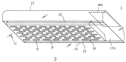
FIG. 15 is a plan view of a heating and cooling unit of the
induction emission air conditioning apparatus according to
Embodiment 4 of the present invention.
FIG. 16 is a plan view of a heating and cooling unit in the
induction emission air conditioning apparatus according to
Embodiment 4 of the present invention wherein a part of an upper
face of a mixer case of a heating and cooling unit is cut away.
FIG. 17 is a sectional side view of an adjustment case and a
mixer case of a heating and cooling unit in the induction emission air
conditioning apparatus according to Embodiment 4 of the present
invention.
FIG. 18 is a sectional view of a whole viewed from the E
direction of FIG. 15.
FIG. 19 is a sectional view for illustrating a main part of an
adjustment case and a mixer case viewed from the F direction of FIG.
17.
FIG. 20 is a perspective view of a heating and cooling unit in
the induction emission air conditioning apparatus according to
CA 02699436 2010-04-08
42
Embodiment 4 of the present invention wherein a part of an upper
face of an adjustment case of a heating and cooling unit is cut away.
FIG. 21 is a brief side view illustrating an example of
attachment and detachment of a lighting system of the heating and
cooling unit, in the induction emission air conditioning apparatus
according to Embodiment 4 of the present invention.
FIG. 22 is a bottom view of the induction emission air
conditioning apparatus according to Embodiment 4 of the present
invention wherein a lighting system is detached, and viewed from
the room inside side.
FIG. 23 is a perspective view of an induction emission air
conditioning apparatus according to Embodiment 6 of the present
invention viewed from a room inside.
FIG. 24 is a perspective view of an induction emission air
conditioning apparatus according to Embodiment7 of the present
invention viewed from a room inside.
FIG. 25 is a perspective view of an induction emission air
conditioning apparatus according to Embodiment 8 of the present
invention wherein a part of an upper face of a casing is cut away,
and viewed from the above.
FIG. 26 is a perspective view of an induction emission air
conditioning apparatus according to Embodiment 8 of the present
invention viewed from a room inside.
FIG. 27 is a perspective view of an induction emission air
conditioning apparatus according to Embodiment 9 of the present
CA 02699436 2010-04-081
43
invention wherein a part of an upper face of a casing is cut away,
and viewed from the above.
FIG. 28 is a perspective view of an induction emission air
conditioning apparatus according to Embodiment 10 of the present
invention wherein a part of an upper face of a casing is cut away,
and viewed from the above.
DETAILED DESCRIPTION
A description will be specifically given below of a case that a
heating and cooling unit according to the present invention is a
so-called pneumatic radiation laminar flow unit of the heating and
cooling apparatus as an example, with reference to the drawings.
The heating and cooling unit (the pneumatic radiation
laminar flow unit) is buried in a ceiling at the room inside, for
example, and adjusts temperature and humidity of adjusted air
(feed air) supplied from an air conditioning apparatus (not
illustrated) so as to supply the air to the room inside.
(Embodiment 1)
FIG. 1 is a perspective view of a heating and cooling unit 1 of
the present invention viewed from the bottom face side thereof, and
FIG. 2 is a plan view of the heating and cooling unit 1 of the present
invention. The heating and cooling unit 1 of the present invention
comprises: a hood (box member) 13; an adjustment case 11 for
receiving air-conditioned air from the air conditioning apparatus
and adjusting the flow of the air-conditioned air; and a mixer case 16
CA 02699436 2010-04-08
44
for mixing air-conditioned air delivered from the adjustment case 11
with circulated air from the room inside and delivering the air to the
room inside.
FIG. 3 is a plan view of the heating and cooling unit 1 of the
present invention wherein a part of an upper face of the mixer case
16 thereof is cut away, FIG. 4 is a sectional side view of the
adjustment case 11 and the mixer case 16 of the heating and cooling
unit 1 of the present invention, FIG. 5 is an overall sectional view
viewed from the E direction of FIG. 2, and FIG. 7 is a sectional view
of a main part of the adjustment case 11 and the mixer case 16
viewed from the F direction of FIG. 4.
The hood 13 of the heating and cooling unit 1 of the present
invention is buried in a ceiling C at room inside S, and the
adjustment case 11 and the mixer case 16 are held inside the hood
13.
The hood 13 is a flat rectangular parallelepiped box member
having a lower opening part 14 at one face thereof. The hood 13 is
buried in the ceiling C in a manner such that the one face having the
lower opening part 14 faces the room inside S so as to form a flat face
with the ceiling C, and a rectangular inspection port 19A is provided
at one end part of the other face opposed to the one face. The
inspection port 19A penetrates the hood 13 from the inside thereof to
the outside thereof, and a cover is provided so as to be openable and
closable. Moreover, a rectangular inspection panel 17A is attached
to the one face of the hood 13 at a position opposed to the inspection
CA 02699436 2010-04-08
45
port 19A so as to be detachable. The inspection panel 17A is
attached at a position close to one end side of the hood 13 in the
vicinity of the inspection port 19A so as to form a flat face with the
ceiling C. The hood 13 of the heating and cooling unit 1 of the
present invention having such a structure can be easily installed
even in a narrow ceiling.
Moreover, the adjustment case 11 is attached to the other
face of the hood 13, the mixer case 16 is located below the
adjustment case 11 so as to be opposed to the adjustment case 11,
and the adjustment case 11 and the mixer case 16 are surrounded by
a side wall of the hood 13. It is to be noted that a circulated air
path 15 for delivering circulated air at the room inside S from the
lower opening part 14 to a guide path K, which will be described
later, is formed between the adjustment case 11 and mixer case 16
and the inside of the hood 13. That is, the circulated air path 15 is
communicatively connected with the room inside (circulated air) so
that circulated air can always enter or exit the circulated air path 15,
and circulated air is suctioned into the guide path K via the
circulated air path 15.
The adjustment case 11 comprises: an air inlet 18 for
receiving air-conditioned air from the air conditioning apparatus; a
holder case part 11B for holding air-conditioned air from the air inlet
18 and adjusting the flow, such as the wind direction, the wind
velocity or the air volume, of air-conditioned air; and an air blowoff
port 12A for blowing adjusted air, the flow of which is adjusted at
CA 02699436 2010-04-08
46
the holder case part 11B, outward from the adjustment case 11.
The air blowoff port 12A has a rectangular shape and is formed at
the lower side of the holder case part 11B, and the adjustment case
11 is constructed to narrow toward the air blowoff port 12A.
The air inlet 18 has a cylindrical shape and is provided to
penetrate the other face of the hood 13 from the inside thereof to the
outside thereof in the vicinity of the inspection port 19A of the hood
13.
With the above structure, maintenance on the heating and
cooling unit 1 can be carried out easily from the inspection panel 17A
without detaching the entire heating and cooling unit 1 from the
ceiling C or providing an inspection port at the ceiling C separately.
Moreover, since the air inlet 18 of the adjustment case 11 is
positioned adjacent to the inspection port 19A, construction,
maintenance and the like of a fan duct (omitted in the drawings) of
air-conditioned air can be carried out using the inspection panel 17A
and the inspection port 19A, and satisfactory workability is realized.
It is to be noted that the present invention is not limited to this and
may be constructed without providing the inspection panel 17A and
the inspection port 19A.
The holder case part 11B is connected with an edge at the
lower side of the air inlet 18, has a taper shape narrowing downward,
and is a box member extended along the longitudinal direction of the
hood 13. A plurality of small wall strip parts 7, 7, ... 7 for guiding
air-conditioned air from the air inlet 18 to the air blowoff port 12A
CA 02699436 2010-04-08
47
and an inclined plate (suppression structure) 11a for suppressing
unevenness of the air volume and the wind velocity of adjusted air to
be blown from the air blowoff port 12A are provided inside the holder
case part 11B.
FIG. 8 is a perspective view of the heating and cooling unit 1
of the present invention wherein a part of an upper face of the
adjustment case 11 thereof is cut away. The holder case part 11B
comprises two opposed inclined walls 7B, 7B, which are inclined in a
symmetric fashion, and the small wall strip parts 7, 7, ... 7 are
provided to protrude from the inside of the respective inclined walls
7B, 7B. The small wall strip parts 7, 7, ... 7 have a rectangular
shape and are juxtaposed at an interval at the inclined walls 7B, 7B
in a manner such that the longitudinal direction thereof is oriented
to the vertical direction. When air-conditioned air from the air
inlet 18 collides with the small wall strip parts 7, 7, ... 7, the wind
direction thereof is changed and the air-conditioned air can be
guided toward the air blowoff port 12A.
The dimension (height) of the small wall strip parts 7, 7, ... 7
in the protrusion direction and the dimension (width) thereof in a
direction crossing the protrusion direction can be freely changed,
though it is preferable to set a vertical cross section of the small wall
strip parts 7, 7, ... 7 to be 10 ¨ 30 % of the maximum cross section in
the direction of the shorter side of the adjustment case 11. This is
because the wind direction cannot be adjusted when the height of
the small wall strip parts 7, 7, ... 7 is too low, while air-conditioned
CA 02699436 2010-04-081
48
air from the air inlet 18 cannot reach the leeward part of the small
wall strip parts 7, 7, ... 7 as indicated by the bold dot-line arrows of
FIG. 4 and a part where air does not flow is generated intermittently
in a space between the bold dot-line arrows and the bold full-line
arrows when the height is too high. It is to be noted that the
full-line arrows in FIG. 4 indicate the wind direction to be generated
by the small wall strip parts 7, 7, ... 7 regardless of the height.
That is to say, in the heating and cooling unit 1 of
Embodiment 1 of the present invention, a rectifier structure G
composed of the inner face of the inclined walls 7B, 7B and the small
wall strip parts 7, 7, ... 7 is provided at the adjustment case 11.
Air-conditioned air which enters the unit from the air inlet 18 is
guided by the rectifier structure G, or more specifically, the wind
direction thereof is changed to vertically downward by resistance of
the inner face of the inclined walls 7B, 7B and the small wall strip
parts 7, 7, ... 7, so that the air-conditioned air flows toward the air
blowoff port 12A.
The inclined plate ha has a rectangular plate shape which is
extended along the longitudinal direction of the holder case part 11B.
The inclined plate 11a is located to be opposed to the air blowoff port
12A in a manner such that the distance from the air blowoff port
12A gradually changes along the longitudinal direction. More
specifically, the inclined plate 11a is attached to be inclined
downward, that is, in a manner such that the distance from the air
blowoff port 12A is the largest in the vicinity of the air inlet 18 and
CA 02699436 2010-04-08
49
gradually decreases with increase in the distance from the air inlet
18. Accordingly, it is possible to prevent occurrence of
ununiformity in the air pressure between an area near to the air
inlet 18 and an area far from the air inlet 18 in the holder case part
11B and to suppress unevenness of the air volume and the wind
velocity of adjusted air to be blown from the air blowoff port 12A.
A partition plate 7a for guiding air-conditioned air from the
air inlet 18 in the longitudinal direction of the adjustment case 11 is
provided directly below the air inlet 18. The partition plate 7a is
located to be opposed to the air inlet 18, and a clearance M is
provided between the partition plate 7a and the inclined walls 7B,
7B. Accordingly, most of air-conditioned air from the air
conditioning apparatus enters the unit from the air inlet 18 collides
with the partition plate 7a, the wind direction thereof is changed to
the longitudinal direction of the adjustment case 11, and only a part
flows through the clearance M toward the air blowoff port 12A.
It is to be noted that the present invention is not limited to
the example explained in Embodiment 1 of the present invention
wherein the adjustment case 11 has a funnel-shaped cross section
(or taper shape) narrowing toward the air blowoff port 12A having a
wide upper part and a thinned lower part as described above.
The mixer case 16 has a flat box shape, is attached in the
hood 13 so as to be detachable and comprises: a mounting part 16B
where a heat storage radiation flow divider (heat storage radiation
member) 2, which will be described later, is attached; and a cover
CA 02699436 2010-04-08
50
part 16A for covering the mounting part 16B. The cover part 16A
and the mounting part 16B are formed in an integrated manner.
The mounting part 16B is a flat rectangular parallelepiped
box member having an opening at one face thereof at the upper side.
The heat storage radiation flow divider 2 for obtaining low heat or
high heat from mixed air and radiating heat toward the room inside
is attached to the inner side of the other face (aperture face) 163 at
the lower side opposed to the one face of the mounting part 16B so as
to be thermally conducted with the mounting part 16B.
Accordingly, heat stored in the heat storage radiation flow divider 2
is transferred to the mounting part 16B and the cover part 16A, and
radiation heat (low heat or high heat) can reach a long-distance
point with high efficiency by carrying out radiation cooling or
radiation heating to the room inside S not only by the heat storage
radiation flow divider 2 but also by the mounting part 16B and the
cover part 16A.
Moreover, a plurality of apertures 9, 9, ... 9 for blowing the
mixed air to the outside (room inside S) are provided at the other
face 163 of the mounting part 16B. The apertures 9, 9, ... 9 are long
holes which penetrate the mixer case 16 (mounting part 16B) from
the inside thereof to the outside thereof. Mixed air in the mixer
case 16 passes the heat storage radiation flow divider 2 and the
apertures 9, 9, ... 9, and is supplied to the room inside. The present
invention is not limited to the example explained in Embodiment 1
of the present invention wherein the apertures 9, 9, ... 9 are long
CA 02699436 2010-04-08
51
holes, and the apertures 9, 9, ... 9 may have a shape such as a round
shape or a rectangular shape. Moreover, the arrangement, the
number or the like of the apertures 9, 9, ... 9 may be changed as
occasion rises.
It is to be noted that it is preferable to set the total area ratio
of the whole area of the apertures 9, 9, ... 9 to the whole area of the
other face 163 of the mixer case 16 (mounting part 16B) equal to or
larger than 30 % in order to maximize the radiation heating action of
the heat storage radiation flow divider 2 and the mixer case 16 to the
room inside S and the heat transfer action by mixed air emission
from the mixer case 16, though the present invention is not limited
to this.
The heat storage radiation flow divider 2 comprises: a
plurality of heat transfer plate(flow dividing fin)s 8, 8, ... 8; and a
plurality of elliptical heat storage pipes 99, 99, ... 99 for storing low
heat or high heat transferred from the heat transfer plates 8, 8, ... 8.
The heat transfer plates 8, 8, ... 8 have a rectangular shape, obtain
low heat or high heat from the mixed air, and transfer heat to the
mounting part 16B, the cover part 16A and the elliptical heat
storage pipes 99, 99, ... 99. The elliptical heat storage pipes 99, 99,
... 99 have an elliptical longitudinal section, and are attached in a
manner such that the major axis direction of the ellipse is oriented
to the vertical direction. Accordingly, mixed air in the mixer case
16 can pass the heat storage radiation flow divider 2 smoothly with a
low pressure loss.
CA 02699436 2010-04-08
52
The heat transfer plates 8, 8, ... 8 are made of, for example,
aluminum, copper, mica, titanium, Carbolite or the like having high
thermal conductivity and high thermal emissivity, and are
juxtaposed to be opposed to each other at a proper interval in the
direction of the shorter side of the mounting part 16B. The
elliptical heat storage pipes 99, 99, ... 99 are installed so as to
penetrate the heat transfer plates 8, 8, ... 8 in the juxtaposition
direction of the heat transfer plates 8, 8, ... 8. It is to be noted that
the elliptical heat storage pipes 99, 99, ... 99 are made of copper,
mica, titanium, Carbolite or the like and are juxtaposed along the
longitudinal direction of the heat transfer plates 8, and the heat
storage radiation flow divider 2 has a flat rectangular parallelepiped
shape as a whole, similar to the inner shape of the mounting part
16B.With such a structure, the wind velocity of mixed air in the
mixer case 16 to pass the heat storage radiation flow divider 2 is
decreased by the heat transfer plates 8, 8, ... 8, the flow of the mixed
air is divided into a plurality of layers and the mixed air is supplied
to the room inside S in a so-called multi-layer flow manner, and
therefore it is possible to suppress the draft to be given to the user of
the room inside S.
It is to be noted that the present invention is not limited to
the example explained in the present embodiment wherein a
plurality of elliptical heat storage pipes 99, 99, ... 99 are provided,
and one long elliptical heat storage pipe 99 may be folded to have a
CA 02699436 2010-04-08
53
meandering shape. Moreover, the elliptical heat storage pipes 99,
99, ... 99 may have not an elliptical cross section but a circular cross
section.
Moreover, the structure of the elliptical heat storage pipes 99,
99, ... 99 is not limited to the above description. FIG. 6 is a
sectional view for illustrating a main part of a variation of a heat
storage radiation flow divider 2 of Embodiment 1 of the present
invention. A heat storage member T for obtaining heat of the
mixed air via the elliptical heat storage pipes 99, 99, ... 99 and
storing the heat is filled in the elliptical heat storage pipes 99, 99, ...
99. The heat storage member T needs only to be made of material
which can store heat and release heat for a long period of time, and
may be in a liquid state or a solid state.
Moreover, the shape, the number, the pitch and the like of
the heat transfer plates 8, 8, ... 8 and the apertures 9, 9, ... 9 are set
in a manner such that the velocity of mixed air before passing the
heat storage radiation flow divider 2 is decreased to be equal to or
lower than half of the velocity of mixed air after passing the heat
storage radiation flow divider 2, or more preferably equal to or lower
than 20 % to 30 %, in order to ensure an optimum function of flow
division, diffusion, heat transfer action and the like of mixed air to
the room inside S.
On the other hand, the cover part 16A is provided to cover the
one face of the mounting part 16B at the upper side. The cover part
16A has a shape to be obtained by folding an outer edge of an upper
CA 02699436 2010-04-08
54
plate 161, which is made of a rectangular plate material having a
size substantially equal to the heat storage radiation flow divider 2,
downward and extending the same. Accordingly, a space
surrounded by the inner face of the cover part 16A and the heat
storage radiation flow divider 2 is formed in the mixer case 16. In
the space, adjusted air from the adjustment case 11 and circulated
air from the circulated air path 15 are mixed by a method, which will
be described later, and become mixed air.
Moreover, in the cover part 16A, an induction port (air
suction port) 162 for suctioning adjusted air from the adjustment
case 11 and inducing and suctioning circulated air from the
circulated air path 15 is provided at a central part (denoted by L in
FIG. 3) in the direction of the shorter side of the upper plate 161.
The induction port 162 has a rectangular shape elongated in the
longitudinal direction of the upper plate 161 and is formed to be
opposed to the air blowoff port 12A of the adjustment case 11. It is
to be noted that the induction port 162 is formed at the midpoint
between two opposed side faces of the upper plate 161 in the lateral
direction and constructed to be matched with the air blowoff port
12A. It is to be noted that the circulated air path 15 is formed
outside the two side faces and the upper plate 161.
Further, the heating and cooling unit 1 according to the
present invention is provided with the guide path K guiding the
adjusted air blown out from the air blowoff port 12A of the
adjustment case 11 to the mixer case 16. The guide path K includes
CA 02699436 2010-04-08I
55
a part of the air blowoff guide 12 (or the air blowoff port air volume
adjustment member 3), and a part of the induction guide 10 (or the
induction port air volume adjustment member 5). More
particularly, the guide path K is constructed by the guide flange 32
of the air blowoff guide 12 (or the air blowoff port air volume
adjustment member 3), the space N, and the guide flange 51 of the
induction guide 10 (or the induction port air volume adjustment
member 5), and the adjusted air blown out from the air blowoff port
12A is guided by the guide path K, and flows into the induction port
162. At this time, the circulated air from the room inside S is
suctioned into the induction port 162 through the guide path K from
the space N via the circulated air path 15.
The air blowoff guide 12 is attached to a lower end part of the
inclined walls 7B, 7B of the adjustment case 11 in the vicinity of the
air blowoff port 12A, and guides the wind direction of adjusted air
blown from the air blowoff port 12A to flow into the induction port
162. Moreover, the air blowoff guide 12 comprises an air volume
adjustment structure A for adjusting the air volume of the adjusted
air. The air volume adjustment structure A is composed of; a pair
of air blowoff port air volume adjustment members 3, 3 attached to
the outer side of a lower end part of the inclined walls 7B, 7B so as to
be slidable; and screw members 4, 4 for fixing the air blowoff port air
volume adjustment members 3, 3 so as to be slidable.
The air blowoff port air volume adjustment members 3, 3 are
made of rectangular plate materials having a longitudinal
CA 02699436 2010-04-08I
56
dimension substantially equal to the longitudinal dimension of the
air blowoff port 12A. An upper end part of each of the air blowoff
port air volume adjustment members 3, 3 in the lateral direction is
fixed at an edge part at each long side of the air blowoff port 12A by
each of the screw members 4, 4 so as to be slidable, and a lower end
part of each of the air blowoff port air volume adjustment members 3,
3 is folded and extended toward the induction port 162 to form each
of guide flanges 32, 32.
For example, a long through hole is provided at an upper end
part of each of the air blowoff port air volume adjustment members 3,
3, and each air blowoff port air volume adjustment member 3 is fixed
by a screw member 4, such as a screw or a rivet, having a diameter
equal to the minor axis of the long through hole so as to be slidable
in the major axis direction of the long through hole. The air volume
of adjusted air to be blown from the air blowoff port 12A can be
adjusted when the pair of air blowoff port air volume adjustment
members 3, 3 slide respectively along the outer face of the inclined
walls 7B, 7B in the incline direction thereof so as to open or close the
air blowoff port 12A, that is, when the interval (HA) between the air
blowoff port air volume adjustment members 3, 3 increases or
decreases. It is to be noted that adjusted air to be blown from the
air blowoff port 12A exits the air blowoff port 12A and then the wind
direction thereof is guided by the guide flanges 32, 32. That is to
say, the air blowoff guide 12 functions to adjust the air volume of the
adjusted air and to guide the adjusted air.
CA 02699436 2010-04-08
57
The induction guide 10 is attached to a central part of the
upper plate 161 in the vicinity of the induction port 162 and guides
adjusted air to be blown from the air blowoff port 12A so as to be
suctioned into the induction port 162 and guides circulated air from
the circulated air path 15 so as to be induced and suctioned. The
induction guide 10 is located to be opposed to the air blowoff guide
12 across the space N as described above.
Moreover, the induction guide 10 comprises an air volume
adjustment structure B for adjusting the volume of air to be
suctioned. The air volume adjustment structure B is composed of a
pair of induction port air volume adjustment members 5, 5 attached
to the outer side of the upper plate 161 so as to be slidable, and
screw members 6, 6 for fixing the induction port air volume
adjustment members 5, 5 so as to be slidable.
The induction port air volume adjustment members 5, 5 are
made of rectangular plate materials having a longitudinal
dimension substantially equal to the longitudinal dimension of the
induction port 162. An outer end part of the central part at the
outer side in the direction of the shorter side of each of the induction
port air volume adjustment members 5, 5 is fixed at an edge part at
each long side of the induction port 162 by each of the screw
members 6, 6 so as to be slidable. Moreover, an inner end part of
each of the induction port air volume adjustment members 5, 5 is
folded and extended toward the inner side of the mixer case 16 so as
to form each of the guide flanges 51, 51.
CA 02699436 2010-04-08
58
For example, a long through hole is provided at an outer end
part of each of the induction port air volume adjustment members 5,
5, and each induction port air volume adjustment member 5 is fixed
by a screw member 6, such as a screw or a rivet, having a diameter
equal to the minor axis of the long through hole so as to be slidable
in the major axis direction of the long through hole. The volume of
air to be suctioned into the induction port 162 can be adjusted when
the pair of induction port air volume adjustment members 5, 5 slide
respectively along the outer face of the upper plate 161 so as to open
or close the induction port 162, that is, when the interval (HB)
between the induction port air volume adjustment members 5, 5
increases or decreases. It is to be noted that the wind direction of
air, which passes the induction port 162, is guided by the guide
flanges 51, 51.
The present invention is not limited to the example explained
in Embodiment 1 of the present invention wherein the lower end
part of the air blowoff port air volume adjustment members 3 and
the inner end part of the induction port air volume adjustment
members 5 are folded. It is to be noted that any one of the air
blowoff guide 12 and the induction guide 10 may be omitted.
The following description will explain a method of inducing
and suctioning circulated air in the circulated air path 15 into the
mixer case 16 and mixing the circulated air with adjusted air from
the adjustment case 11 so as to make mixed air.
When adjusted air blown from the air blowoff port 12A (air
CA 02699436 2010-04-08i
59
blowoff guide 12) is suctioned into the induction port 162 (induction
guide 10), the air pressure around the air flow from the air blowoff
port 12A to the induction port 162 lowers. On the other hand, the
air blowoff guide 12 (air blowoff port 12A) and the induction guide 10
(induction port 162) in Embodiment 1 are located in opposed
positions across the space N, through which air in the vicinity
(circulated air in the circulated air path 15) flows into the induction
guide 10 (the induction port 162). Accordingly, when the air
pressure around the air flow lowers, circulated air in the circulated
air path 15 is caught up in the air flow (as indicated by the dot-line
arrows W1 in FIG. 5). Circulated air induced in such a manner is
suctioned into the mixer case 16 together with adjusted air and is
mixed with the adjusted air, the flow of the air is divided, (as
indicated by the dot-line arrows W2 in FIG. 5) and the air is supplied
to the room inside S. At this time, it is preferable to set the ratio of
adjusted air and circulated air to approximately 6:4, though the
present invention is not limited to this.
It is to be noted that the air pressure in the circulated air
path 15 lowers by the volume of circulated air suctioned into the
mixer case 16 at this time, and circulated air is supplied from the
room inside (as indicated by the dot-line arrows W3 in FIG. 5) since
the circulated air path 15 is communicatively connected with the
room inside (circulated air) as described above.
By repeating the above operation, air is convected, circulated
and stirred between the room inside S and the heating and cooling
CA 02699436 2010-04-08
60
unit 1. The room inside S is air-conditioned by mixed air having a
temperature lower than the room inside S and low heat emission at
the time of cooling, while the room inside S is air-conditioned by
mixed air having a temperature higher than the room inside S and
high heat emission at the time of heating. Air-conditioned air is set,
for example, to have a temperature higher than the dew-point
temperature of the room inside S and a low absolute humidity when
mixed with circulated air in order to prevent dew condensation and
enhance the air conditioning efficiency, though the present invention
is not limited to this.
Moreover, the guide path K is not limited to such a structure.
For example, the feed path K may be constructed without providing
the air blowoff guide 12 and the induction guide 10. Moreover, the
feed path K may be constructed by connecting the air blowoff port
12A with the induction port 162 by a guide path member such as
bellows and providing a hole at the guide path member so as to be
communicated with circulated air in the circulated air path 15.
(Embodiment 2)
FIG. 9 is a sectional view of a main part of a heating and
cooling unit 1 of Embodiment 2 of the present invention. In the
heating and cooling unit 1 of Embodiment 2, a lighting system R for
lighting room inside S is provided at an edge part of a lower opening
part 14 of a hood 13.
The size of the other face 163 of a mounting part 16B is
smaller than the size of the lower opening part 14 of the hood 13,
CA 02699436 2010-04-08
61
and a clearance (passage clearance) 141 is formed between the lower
opening part 14 of the hood 13 and the other face 163 of the
mounting part 16B when the heating and cooling unit 1 is installed.
Circulated air from the room inside S passes the clearance 141 and
is suctioned into a circulated air path 15.
The lighting system R is provided at the clearance 141 in a
proper manner. The lighting system R is provided so as not to
obstruct circulated air passing the clearance 141, so that circulated
air can pass freely. That is to say, the lighting system R is exposed
to circulated air passing the clearance 141. Accordingly, circulated
air passing the clearance 141 comes into contact with the lighting
system R and obtains heat generated by the lighting system R. The
obtained heat is used for reheating or preheating in mixing of the
air-conditioned air and circulated air. That is, at the time of cooling
with a large cooling capacity per unit air volume of the
air-conditioned air (when the air supply temperature is lowered
than usual), heat from the lighting system R is used for reheating of
air-conditioned air and therefore it is possible to prevent dew
condensation reliably and to further decrease the air supply volume
of air-conditioned air so as to further reduce the cost. Moreover, at
the time of heating, heat from the lighting system R is used for
preheating of air-conditioned air and therefore it is possible to
decrease the capacity of a device for feeding the air-conditioned air
and to enhance the heating capacity.
The lighting system R is, for example, a fluorescent tube, an
CA 02699436 2010-04-08
62
incandescent lamp or an LED, and the number, the position thereof
or the like can be changed in a proper manner.
Identical codes are used to refer to parts identical to those of
Embodiment 1, and detailed explanation thereof will be omitted.
(Embodiment 3)
FIG. 10 is a sectional view of a main part of a heat storage
radiation flow divider 2 of Embodiment 3 of the present invention
wherein a part thereof is omitted, and FIG. 11 is a sectional view of a
main part of a mixer case 16 and a heat storage radiation flow
divider 2 of Embodiment 3 viewed from the J direction of FIG. 10.
A heating and cooling unit 1 of Embodiment 3 comprises
short tubular protrusions 98, 98, 98, ... 98 formed to protrude from
one face of each heat transfer plate 8.
The protrusions 98, 98, 98, ... 98 are juxtaposed at one face of
each heat transfer plate 8 at a proper interval along the longitudinal
direction of the heat transfer plate 8. More particularly, apertures
9 are juxtaposed below the respective protrusions 98 at a
predetermined interval as illustrated in FIG. 10. The protrusions
98 have an elliptical cross section and are provided in a manner such
that the major axis direction of the ellipse is oriented to the vertical
direction. Moreover, the protrusions 98, 98, 98, ... 98 are further
juxtaposed in the juxtaposition direction of the heat transfer plates 8,
8, 8, ... 8 with each central axis thereof being positioned on the same
line.
The protrusions 98 have heat storage capability, and obtain
CA 02699436 2010-04-08
63
heat from mixed air via the heat transfer plates 8, store the heat and
radiate the heat toward the room inside S. A protrusion 98 of one
heat transfer plate 8 is extended to come into contact with another
adjacent heat transfer plate 8 and supports the adjacent heat
transfer plate 8 so as to prevent warping of the adjacent heat
transfer plate 8.
The following description will explain the action of the
protrusions 98.
Radiation heating to the room inside S by the heat storage
radiation flow divider 2 is directed downward via the apertures 9, 9,
9, ... 9. In such a manner, since heat proceeds getting around the
protrusions 98 as indicated by the dot-line arrows in FIG. 11,
radiation heating is directed obliquely downward from the apertures
9 in the vicinity of a local area below the protrusions 98. That is,
radiation heating in the vicinity of the protrusions 98 widely moves
directly downward and obliquely downward from the apertures 9
since heat moves downward along the peripheral face of the
protrusions 98. Accordingly, it is possible to uniform the
temperature distribution at the room inside S.
Moreover, since the flow of mixed air to pass the apertures 9,
9, 9, ... 9 is further divided not only by the heat transfer plates 8, 8,
... 8 but also by the protrusions 98, 98, 98, ... 98, the wind velocity of
the mixed air is further lowered and the mixed air is supplied to the
room inside S in a further fine multi-layer flow manner and
therefore it is possible to suppress the draft to be given to the user of
CA 02699436 2010-04-08
64
the room inside S.
The present invention is not limited to the example explained
in Embodiment 3 wherein the protrusion 98 of one heat transfer
plate 8 is extended to come into contact with another adjacent heat
transfer plate 8, and a protrusion 98 of one heat transfer plate 8 may
be extended in a proper manner to the vicinity of another adjacent
heat transfer plate 8. Moreover, the protrusion 98 may be formed
to be integrated with a heat transfer plate 8, or may be constructed
so as to be detachable.
Moreover, the present invention is not limited to the example
explained in Embodiment 3 wherein the protrusions 98 have an
elliptical shape, and the protrusions 98 may have a circular shape or
a polygonal shape.
Identical codes are used to refer to parts identical to those of
Embodiment 1, and detailed explanation thereof will be omitted.
A description will be specifically given below of a case that
the heating and cooling apparatus according to the present
invention is a so-called induction emission air conditioning
apparatus as an example, with reference to the drawings.
(Embodiment 4)
FIG. 12 is a perspective view illustrating the case of
installing an induction emission air conditioning apparatus
according to Embodiment 4 of the present invention in a ceiling
wherein a part of an upper face thereof is cut away, and viewed from
the above, FIG. 13 is a perspective view of the induction emission air
CA 02699436 2010-04-08
65
conditioning apparatus according to Embodiment 4 of the present
invention viewed from a room inside side thereof, and FIG. 14 is a
brief explanatory view illustrating an example of usage of the
induction emission air conditioning apparatus according to
Embodiment 4 of the present invention.
The induction emission air conditioning apparatus according
to Embodiment 4 of the present invention is provided with the
casing 19 buried in the ceiling C at the room inside S, and the inner
side of the casing 19 is provided with the heat exchanger 20 through
which the feed air induced from the outdoor side passes, and the fan
22 passing the feed air through the heat exchanger 20. Further,
the inner side of the casing 19 is provided with the heating and
cooling unit 1 for blowing the mixed air obtained by inducing and
suctioning the air in the room inside S by the feed air passing
through the heat exchanger 20 and mixing with the feed air to the
room inside S in a laminar manner, and emitting the heat of the
mixed air to the room inside S, and the lighting system R for lighting
the room inside S. Further, the inner side of the casing 19 is
provided with the air blowing path 24 communicating and coupling
the heat exchanger 20, the fan 22 and the heating and cooling unit 1,
the detector 28 such as a human sensing sensor or the like detecting
existence, a position or the like of a human body in the room inside S
so as to output a signal according to a detection result, and a
controller 29 for controlling one or both of the air conditioning
performance (increase / decrease or on and off of the air volume, the
CA 02699436 2010-04-08
66
air blowoff temperature or the like) and the light modulation of the
lighting system (increase / decrease or on and off of the illumination
intensity) in response to the signal from the detector 28. It is to be
noted that they are integrated. Since the induction emission air
conditioning apparatus according to the present invention has the
structure mentioned above, it can be easily installed even in a
narrow back side of a ceiling.
The space in the back side of the ceiling C serves as a
so-called ceiling chamber. In other words, the air in the back side
(the ceiling chamber) of the ceiling C is passed through the heat
exchanger 20 as the feed air. The feed air includes the processed
external air in which temperature and humidity is controlled by an
outside adjusting apparatus (not illustrated) or the like, the raw
external air in which temperature and humidity is not controlled,
the mixed air of the processed external air and the circulate air from
the room inside S, the mixed air of the raw external air and the
circulated air, the circulated air, or the like.
Further, the heat exchanger 20 is provided with the heat
transfer pipe, and the heat transfer pipe is an elliptical pipe. As
the heat exchanger 20, it is possible to utilize various systems such
as a hot / cold water coil heat exchanging the air to be fed by the cold
water or the hot water, a direct expanding coil heat exchanging the
air to be fed by the refrigerant of the water heat source or the air
heat source heat pump, and the like, and it is not limited to an
illustrated example. In this case, in the drawing, reference
CA 02699436 2010-04-08i
67
numeral 31 denotes a drain pan.
The casing 19 is a flat rectangular parallelepiped shape
which is formed into a rectangular shape in a plan view, and is
provided with the induction port 30 in one side face for suctioning
the feed air. The heat exchanger 20 is arranged in one, and the fan
22 carrying out the air blowing is arranged in the other, in both ends
of the heating and cooling unit 1 which is formed into a rectangular
shape in a bottom view.
The heating and cooling unit 1 within the casing 19 is formed
into a flat rectangular parallelepiped shape in which a dimension in
a short direction is slightly shorter than the casing 19, and is
provided in such a manner that its longitudinal direction coincides
with a longitudinal direction of the casing 19. It is to be noted that
the lighting system R is provided in both end sides in the
longitudinal direction of the heating and cooling unit 1. In other
words, the lighting system R is arranged in a lower side of each of
the heat exchanger 20 and the fan 22.
The air blowing path 24 is formed in the upper side of the
heating and cooling unit 1. The air blowing path 24 has a
windward side wind path 25 communicating and coupling the heat
exchanger 20 and the fan 22, and a leeward side wind path 26
communicating and coupling the fan 22 and the heating and cooling
unit 1.
The windward side wind path 25 and the leeward side wind
path 26 are juxtaposed, and are structured in such a manner that
CA 02699436 2010-04-08
68
the wind directions are reversed to each other. The feed air from
the leeward side wind path 26 flows into the heating and cooling
unit 1 via the air inlet 18. The air inlet 18 is formed in the upper
face of the heating and cooling unit 1 in the vicinity of the heat
exchanger 20 which is spaced from the fan 22. In other words, it is
structured such that the air blowing distance of the feed air from the
induction port 30 to the air inlet 18 becomes longer. In the
illustrated example, the air blowing path 24 constructed by the
windward side wind path 25 and the leeward side wind path 26 is
constructed by comparting by the partition plate 21 with
communication port and the duct member 23, however, the structure
may be freely changed.
The feed air flows based on the drive of the fan 22, according
to the order of induction port 30 ¨> heat exchanger 20 ¨> windward
side wind path 25 ¨> fan 22 ¨> leeward side wind path 26 ¨> air inlet
18 ¨> heating and cooling unit 1. In the illustrated case, since the
fan 22 and the induction port 30 back away, and the air blowing
distance is long, a comfortable low noise operation can be achieved.
In this case, these structures can be freely changed, and although an
illustration is omitted, the structure may be made, for example such
that the feed air is induced from the fan 22 side by changing the
communication position between the windward side wind path 25
and the leeward side wind path 26 and the position of the induction
port 30, and flows according to the order of fan 22 ¨> heat exchanger
20 ¨> heating and cooling unit 1.
CA 02699436 2010-04-08
69
FIG. 15 is a plan view of the heating and cooling unit 1 of the
induction emission air conditioning apparatus according to
Embodiment 4 of the present invention. The heating and cooling
unit 1 is provided with a hood 13, an adjustment case 11 for
receiving the feed air and adjusting the flow of the feed air, and a
mixer case 16 for mixing the adjusted air delivered from the
adjustment case 11 with the circulated air from the room inside so as
to feed to the room inside.
FIG. 16 is a plan view of the heating and cooling unit 1 in the
induction emission air conditioning apparatus according to
Embodiment 4 of the present invention wherein a part of an upper
face of the mixer case 16 of the heating and cooling unit 1 is cut
away, FIG. 17 is a sectional side view of the adjustment case 11 and
the mixer case 16 of the heating and cooling unit 1 in the induction
emission air conditioning apparatus according to Embodiment 4 of
the present invention, FIG. 18 is a sectional view of a whole viewed
from the E direction of FIG. 15, and FIG. 19 is a sectional view for
illustrating a main part of the adjustment case 11 and the mixer
case 16 viewed from the F direction of FIG. 17.
The hood 13 of the heating and cooling unit 1 according to the
present invention is provided in the casing 19, and the adjustment
case 11 and the mixer case 16 are housed inside the hood 13.
The hood 13 is a flat rectangular parallelepiped box member
having a lower opening part 14 in one face. The hood 13 is provided
in such a manner that the one face having the lower opening part 14
CA 02699436 2010-04-081
70
is directed to the room inside S while being flush with the ceiling C.
Further, the adjustment case 11 is attached to the other face
which is opposed to the one face of the hood 13, the mixer case 16 is
arranged below the adjustment case 11 so as to be opposed to the
adjustment case 11, and they are surrounded by the side wall of the
hood 13. It is to be noted that a circulated air path 15
communicatively connecting the circulated air in the room inside S
from the lower opening part 14 to the guide path K mentioned above
is formed between the adjustment case 11 and the mixer case 16,
and the inner side of the hood 13. In other words, the circulated air
path 15 is communicatively connected with the room inside (the
circulated air), and is structured such that the circulated air can
always come in and out the circulated air path 15, and the circulated
air is suctioned into the guide path K via the circulated air path 15.
The adjustment case 11 is provided with an air inlet 18 which
is continuously provided in the air blowing path 24 so as to receive
the feed air, a holder case part 11B which holds the feed air from the
air inlet 18, and adjusts the flow such as the wind direction, the
wind velocity, the air volume of the feed air, and a air blowoff port
12A which blows off the adjusted air having the flow adjusted by the
holder case part 11B toward the outer side of the adjustment case 11.
The air blowoff port 12A is formed into a rectangular shape, and is
formed in a lower side of the holder case part 11B, and the
adjustment case 11 is structured such as to be narrowed toward the
air blowoff port 12A.
CA 02699436 2010-04-08i
71
The holder case part 11B is a box member which has a taper
shape which narrows toward a lower side, and extends along a
longitudinal direction of the hood 13. The inner side of the holder
case part 11B is provided with a plurality of small wall strip parts 7,
7, ... 7 for guiding the feed air from the air inlet 18 to the air blowoff
port 12A, and a inclined plate 11a for suppressing unevenness of the
air volume and the wind velocity of the adjusted air blown out from
the air blowoff port 12A.
FIG. 20 is a perspective view of a heating and cooling unit in
the induction emission air conditioning apparatus according to
Embodiment 4 of the present invention wherein a part of an upper
face of an adjustment case of a heating and cooling unit. The
holder case part 11B is provided with two opposed inclined walls 7B
and 7B which are inclined symmetrically, and the small wall strip
parts 7, 7, ... 7 are provided to protrude from the inside of the
respective inclined walls 7B and 7B. The small wall strip parts 7, 7,
... 7 have the rectangular shape, and are juxtaposed at an interval at
the inclined walls 7B and 7B in a manner such that the longitudinal
direction thereof is oriented to the vertical direction. When feed air
from the air inlet 18 collides with the small wall strip parts 7, 7, ... 7,
the wind direction thereof is changed and the feed air can be guided
toward the air blowoff port 12A.
The dimension (height) of the small wall strip parts 7, 7, ... 7
in the protrusion direction and the dimension (width) thereof in a
direction crossing the protrusion direction can be freely changed,
CA 02699436 2010-04-08
72
though it is preferable to set the vertical cross section of the small
wall strip parts 7, 7, ... 7 to be 10 ¨ 30 % of the maximum cross
section in the direction of the shorter side of the adjustment case 11.
This is because the wind direction cannot be adjusted when the
height of the small wall strip parts 7, 7, ... 7 is too low, while feed air
from the air inlet 18 cannot reach the leeward part of the small wall
strip parts 7, 7, ... 7 as indicated by the bold dot-line arrows of FIG.
17 and a part where air does not flow is generated intermittently in
a space between the bold dot-line arrows and the bold full-line
arrows when the height is too high. It is to be noted that the
full-line arrows in FIG. 17 indicate the wind direction to be
generated by the small wall strip parts 7, 7, ... 7 regardless of the
height.
In other words, in the heating and cooling unit 1 according to
Embodiment 4 of the present invention, a rectifier structure G
composed of the inner face of the inclined walls 7B, 7B and the small
wall strip parts 7, 7, ... 7 is provided at the adjustment case 11.
The feed air entering from the air inlet 18 is guided by the rectifier
structure G or more specifically, the wind direction thereof is
changed to vertically downward by resistance of the inner face of the
inclined walls 7B, 7B and the small wall strip parts 7, 7, ... 7, so that
the feed air flows toward the air blowoff port 12A.
The inclined plate 11a has a rectangular plate shape which is
extended along the longitudinal direction of the holder case part 11B.
The inclined plate 11a is located to be opposed to the air blowoff port
CA 02699436 2010-04-08i
73
12A in a manner such that the distance from the air blowoff port
12A gradually changes along the longitudinal direction. More
specifically, the inclined plate 11a is attached to be inclined
downward, that is, in a manner such that the distance from the air
blowoff port 12A is the largest in the vicinity of the air inlet 18 and
gradually decreases with increase in the distance from the air inlet
18. Accordingly, it is possible to prevent occurrence of
ununiformity in the air pressure between an area near to the air
inlet 18 and an area far from the air inlet 18 in the holder case part
11B and to suppress unevenness of the air volume and the wind
velocity of adjusted air to be blown from the air blowoff port 12A.
A partition plate 7a for guiding feed air from the air inlet 18
in the longitudinal direction of the adjustment case 11 is provided
directly below the air inlet 18. The partition plate 7a is located to
be opposed to the air inlet 18, and a clearance M is provided between
the partition plate 7a and the inclined walls 7B, 7B. Accordingly,
most of feed air entering from the air inlet 18 collides with the
partition plate 7a, the wind direction thereof is changed to the
longitudinal direction of the adjustment case 11, and only a part
flows through the clearance M toward the air blowoff port 12A.
It is to be noted that the present invention is not limited to
the example explained in Embodiment 4 of the present invention
wherein the adjustment case 11 has a funnel-shaped cross section
(or taper shape) narrowing toward the air blowoff port 12A having a
wide upper part and a thinned lower part as described above.
CA 02699436 2010-04-08
74
The mixer case 16 is the same as the mixer case 16 according
to Embodiment 1 illustrated in FIG. 6. More particularly, the
mixer case 16 according to Embodiment 4 is formed into the flat box
shape, is detachably mounted in the hood 13, and is provided with
an mounting part 16B to which the heat storage radiation flow
divider 2 mentioned above is attached, and a cover part 16A for
covering the mounting part 16B, and the cover part 16A and the
mounting part 16B are formed in an integrated manner (hereinafter,
see FIG. 6).
The mounting part 16B is a flat rectangular parallelepiped
box member in which one upper face is open. The heat storage
radiation flow divider 2 for obtaining low heat or high heat from the
mixed air so as to radiate heat toward the room inside is provided in
the inner side of the other face 163 at the lower side opposed to the
one face of the mounting part 16B so as to be thermally conducted
with the mounting part 16B (and cover part 16A). Accordingly,
heat stored in the heat storage radiation flow divider 2 is transferred
to the mounting part 16B and the cover part 16A, and radiation heat
(low heat or high heat) can reach a long-distance point with high
efficiency by carrying out radiation cooling or radiation heating to
the room inside S not only by the heat storage radiation flow divider
2 but also by the mounting part 16B and the cover part 16A.
Moreover, a plurality of apertures 9, 9, ... 9 for blowing the
mixed air to the outside (room inside S) are provided at the other
face 163 of the mounting part 16B. The apertures 9, 9, ... 9 are long
CA 02699436 2010-04-08i
75
holes which penetrate the mixer case 16 (mounting part 16B) from
the inside thereof to the outside thereof. Mixed air in the mixer
case 16 passes the heat storage radiation flow divider 2 and the
apertures 9, 9, ... 9, and is supplied to the room inside. The present
invention is not limited to the example explained in Embodiment 4
of the present invention wherein the apertures 9, 9, ... 9 are long
holes, and the apertures 9, 9, ... 9 may have a shape such as a round
shape or a rectangular shape. Moreover, the arrangement, the
number or the like of the apertures 9, 9, ... 9 may be changed as
occasion rises.
It is to be noted that it is preferable to set the total area ratio
of the whole area of the apertures 9, 9, ... 9 to the whole area of the
other face 163 of the mixer case 16 (mounting part 16B) equal to or
larger than 30 % in order to maximize the radiation heating action of
the heat storage radiation flow divider 2 and the mixer case 16 to the
room inside S and the heat transfer action by mixed air emission
from the mixer case 16, though the present invention is not limited
to this.
The heat storage radiation flow divider 2 comprises: a
plurality of heat transfer plates 8, 8, ... 8; and a plurality of elliptical
heat storage pipes 99, 99, ... 99 for storing low heat or high heat
transferred from the heat transfer plates 8, 8, ... 8. The heat
transfer plates 8, 8, ... 8 have a rectangular shape, obtain low heat
or high heat from the mixed air, and transfer heat to the mounting
part 16B, the cover part 16A and the elliptical heat storage pipes 99,
CA 02699436 2010-04-08
76
99, ... 99. The elliptical heat storage pipes 99, 99, ... 99 have an
elliptical longitudinal section, and are attached in a manner such
that the major axis direction of the ellipse is oriented to the vertical
direction. Accordingly, mixed air in the mixer case 16 can pass the
heat storage radiation flow divider 2 smoothly with a low pressure
loss.
The heat transfer plates 8, 8, ... 8 are made of, for example,
aluminum, copper, mica, titanium, Carbolite or the like having high
thermal conductivity and high thermal emissivity, and are
juxtaposed to be opposed to each other at a proper interval in the
direction of the shorter side of the mounting part 16B. The
elliptical heat storage pipes 99, 99, ... 99 are installed so as to
penetrate the heat transfer plates 8, 8, ... 8 in the juxtaposition
direction of the heat transfer plates 8, 8, ... 8. It is to be noted that
the elliptical heat storage pipes 99, 99, ... 99 are made of copper,
mica, titanium, Carbolite or the like and are juxtaposed along the
longitudinal direction of the heat transfer plates 8, and the heat
storage radiation flow divider 2 has a flat rectangular parallelepiped
16B.shape as a whole, similar to the inner shape of the mounting part
With such a structure, the wind velocity of mixed air in the
mixer case 16 to pass the heat storage radiation flow divider 2 is
decreased by the heat transfer plates 8, 8, ... 8, the flow of the mixed
air is divided into a plurality of layers and the mixed air is supplied
to the room inside S in a so-called laminar manner, and therefore it
CA 02699436 2010-04-08
77
is possible to suppress the draft to be given to the user of the room
inside S.
It is to be noted that the present invention is not limited to
the example explained in the present embodiment wherein a
plurality of elliptical heat storage pipes 99, 99, ... 99 are provided,
and one long elliptical heat storage pipe 99 may be folded to have a
meandering shape. Moreover, the elliptical heat storage pipes 99,
99, ... 99 may have not an elliptical cross section but a circular cross
section.
Moreover, the structure of the elliptical heat storage pipes 99,
99, ... 99 is not limited to the above description. A heat storage
member T for obtaining heat of the mixed air via the elliptical heat
storage pipes 99, 99, ... 99 and storing the heat is filled in the
elliptical heat storage pipes 99, 99, ... 99. The heat storage member
T needs only to be made of material which can store heat and release
heat for a long period of time, and may be in a liquid state or a solid
state.
Moreover, the shape, the number, the pitch and the like of
the heat transfer plates 8, 8, ... 8 and the apertures 9, 9, ... 9 are set
in a manner such that the velocity of mixed air before passing the
heat storage radiation flow divider 2 is decreased to be equal to or
lower than half of the velocity of mixed air after passing the heat
storage radiation flow divider 2, or more preferably equal to or lower
than 20 % to 30 %, in order to ensure an optimum function of flow
division, diffusion, heat transfer action and the like of mixed air to
CA 02699436 2010-04-08i
78
the room inside S.
On the other hand, the cover part 16A is provided to cover the
one face of the mounting part 16B at the upper side. The cover part
16A has a shape to be obtained by folding an outer edge of an upper
plate 161, which is made of a rectangular plate material having a
size substantially equal to the heat storage radiation flow divider 2,
downward and extending the same. Accordingly, a space
surrounded by the inner face of the cover part 16A and the heat
storage radiation flow divider 2 is formed in the mixer case 16. In
the space, adjusted air from the adjustment case 11 and circulated
air from the circulated air path 15 are mixed by a method described
above, and become mixed air (see the description of FIG. 5).
Moreover, in the cover part 16A, an induction port (air
suction port) 162 for suctioning adjusted air from the adjustment
case 11 and inducing and suctioning circulated air from the
circulated air path 15 is provided at a central part (denoted by L in
FIG. 16) in the direction of the shorter side of the upper plate 161.
The induction port 162 has a rectangular shape elongated in the
longitudinal direction of the upper plate 161 and is formed to be
opposed to the air blowoff port 12A of the adjustment case 11. It is
to be noted that the induction port 162 is formed at the midpoint
between two opposed side faces of the upper plate 161 in the lateral
direction and constructed to be matched with the air blowoff port
12A. It is to be noted that the circulated air path 15 is formed
outside the two side faces and the upper plate 161.
CA 02699436 2010-04-08
79
Further, the heating and cooling unit 1 according to the
present invention is provided with the air blowoff guide 12 which is
attached in the vicinity of the air blowoff port 12A of the adjustment
case 11, and the induction guide 10 which is arranged so as to be
opposed to the air blowoff guide 12 with the space N being
sandwiched therebetween, and is attached in the vicinity of the
induction port 162 of the mixer case 16.
The air blowoff guide 12 is attached to a lower end part of the
inclined walls 7B, 7B of the adjustment case 11 in the vicinity of the
air blowoff port 12A, and guides the wind direction of adjusted air
blown from the air blowoff port 12A to flow into the induction port
162. Moreover, the air blowoff guide 12 comprises an air volume
adjustment structure A for adjusting the air volume of the adjusted
air. The air volume adjustment structure A is composed of: a pair
of air blowoff port air volume adjustment members 3, 3 attached to
the outer side of a lower end part of the inclined walls 7B, 7B so as to
be slidable; and screw members 4, 4 for fixing the air blowoff port air
volume adjustment members 3, 3 so as to be slidable.
The air blowoff port air volume adjustment members 3, 3 are
made of rectangular plate materials having a longitudinal
dimension substantially equal to the longitudinal dimension of the
air blowoff port 12A. An upper end part of each of the air blowoff
port air volume adjustment members 3, 3 in the lateral direction is
fixed at an edge part at each long side of the air blowoff port 12A by
each of the screw members 4, 4 so as to be slidable, and a lower end
CA 02699436 2010-04-081
80
part of each of the air blowoff port air volume adjustment members 3,
3 is folded and extended toward the induction port 162 to form each
of guide flanges 32, 32.
For example, a long through hole is provided at an upper end
part of each of the air blowoff port air volume adjustment members 3,
3, and each air blowoff port air volume adjustment member 3 is fixed
by a screw member 4, such as a screw or a rivet, having a diameter
equal to the minor axis of the long through hole so as to be slidable
in the major axis direction of the long through hole. The air volume
of adjusted air to be blown from the air blowoff port 12A can be
adjusted when the pair of air blowoff port air volume adjustment
members 3, 3 slide respectively along the outer face of the inclined
walls 7B, 7B in the incline direction thereof so as to open or close the
air blowoff port 12A, that is, when the interval (HA) between the air
blowoff port air volume adjustment members 3, 3 increases or
decreases. It is to be noted that adjusted air to be blown from the
air blowoff port 12A exits the air blowoff port 12A and then the wind
direction thereof is guided by the guide flanges 32, 32. That is to
say, the air blowoff guide 12 functions to adjust the air volume of the
adjusted air and to guide the adjusted air.
The induction guide 10 is attached to a central part of the
upper plate 161 in the vicinity of the induction port 162 and guides
adjusted air to be blown from the air blowoff port 12A so as to be
suctioned into the induction port 162 and guides circulated air from
the circulated air path 15 so as to be induced and suctioned. The
CA 02699436 2010-04-08
81
induction guide 10 is located to be opposed to the air blowoff guide
12 across the space N as described above.
Moreover, the induction guide 10 comprises an air volume
adjustment structure B for adjusting the volume of air to be
suctioned. The air volume adjustment structure B is composed of; a
pair of induction port air volume adjustment members 5, 5 attached
to the outer side of the upper plate 161 so as to be slidable; and
screw members 6, 6 for fixing the induction port air volume
adjustment members 5, 5 so as to be slidable.
The induction port air volume adjustment members 5, 5 are
made of rectangular plate materials having a longitudinal
dimension substantially equal to the longitudinal dimension of the
induction port 162. An outer end part of the central part at the
outer side in the direction of the shorter side of each of the induction
port air volume adjustment members 5, 5 is fixed at an edge part at
each long side of the induction port 162 by each of the screw
members 6, 6 so as to be slidable. Moreover, an inner end part of
each of the induction port air volume adjustment members 5, 5 is
folded and extended toward the inner side of the mixer case 16 so as
to form each of the guide flanges 51, 51.
For example, a long through hole is provided at an outer end
part of each of the induction port air volume adjustment members 5,
5, and each induction port air volume adjustment member 5 is fixed
by a screw member 6, such as a screw or a rivet, having a diameter
equal to the minor axis of the long through hole so as to be slidable
CA 02699436 2010-04-08i
82
in the major axis direction of the long through hole. The volume of
air to be suctioned into the induction port 162 can be adjusted when
the pair of induction port air volume adjustment members 5, 5 slide
respectively along the outer face of the upper plate 161 so as to open
or close the induction port 162, that is, when the interval (HB)
between the induction port air volume adjustment members 5, 5
increases or decreases. It is to be noted that the wind direction of
air, which passes the induction port 162, is guided by the guide
flanges 51, 51.
Further, the heating and cooling unit 1 according to the
present invention forms the guide path K for guiding the adjusted
air blown out from the air blowoff port 12A of the adjustment case 11
to the mixer case 16. The guide path K includes a part of the air
blowoff guide 12 (or the air blowoff port air volume adjustment
member 3), and a part of the induction guide 10 (or the induction
port air volume adjustment member 5). More particularly, the
guide path K is constructed, by the guide flange 32 of the air blowoff
guide 12 (or the air blowoff air volume adjustment member 3), the
space N, and the guide flange 51 of the induction guide 10 (or the
induction port air volume adjustment member 5), and the adjusted
air blown off from the air blowoff port 12A is guided by the guide
path K, and flows into the induction port 162. At this time, the
circulated air from the room inside S is suctioned into the induction
port 162 through the guide path K from the space N via the
circulated air path 15.
CA 02699436 2010-04-08i
83
In Embodiment 4 according to the present invention, the
description is given of the case that the lower end part of the air
blowoff port air volume adjustment member 3 and the inner end
part of the induction port air volume adjustment member 5 are
formed into the folded shape as the example, however, it is not
limited to this. In this case, the structure may be made such that
any one of the air blowoff guide 12 and the induction guide 10 is
omitted.
On the other hand, the magnitude of the other face 163 of the
mounting part 16B is smaller than the magnitude of the lower
opening part 14 of the hood 13, and a clearance 141 is formed
between the lower opening part 14 of the hood 13 and the other face
163 of the mounting part 16B. The circulated air from the room
inside S passes through the clearance 141 and is suctioned into the
circulated air path 15.
FIG. 21 is a brief side view illustrating an example of
attachment and detachment of a lighting system R of the heating
and cooling unit 1, in the induction emission air conditioning
apparatus according to Embodiment 4 of the present invention, and
FIG. 22 is a bottom view of the induction emission air conditioning
apparatus wherein the lighting system S is detached, and viewed
from the room inside side.
The casing 19 is provided with an opening part 27 such that it
is possible to face the heat exchanger 20 and the fan 22 from the
room inside S by removing its lower face. And the lighting system R
CA 02699436 2010-04-08
84
is provided in such a manner as to be freely opened and closed or be
detachable via the opening part 27.
As mentioned above, the lighting system R is provided in
each of both end sides in the longitudinal direction of the heating
and cooling unit 1 in the vicinity of the clearance 141. In other
words, it is structured such that a part of the circulated air comes
into contact with the lighting system R when it passes through the
clearance 141. Accordingly, the circulated air obtains the heat
generated by the lighting system R, at a time of passing through the
clearance 141. The obtained heat is used for reheating or
preheating in the mixing of the feed air and the circulated air. In
other words, at the time of cooling with a large cooling capacity per
unit air volume of the feed air (when the air supply temperature is
lowered than usual), heat from the lighting system R is used for
reheating of feed air and therefore it is possible to prevent dew
condensation reliably and to further decrease the air supply volume
of feed air so as to further reduce the cost. Moreover, at the time of
heating, heat from the lighting system R is used for preheating of
feed air and therefore it is possible to decrease the capacity of a
device for feeding the feed air and to enhance the heating capacity.
The lighting system R is, for example, a fluorescent tube, an
incandescent lamp or an LED, and the number, the position thereof
or the like can be changed in a proper manner.
Identical codes are used to refer to parts identical to those of
Embodiment 4, and detailed explanation thereof will be omitted.
CA 02699436 2010-04-08
85
(Embodiment 5)
A heating and cooling unit 1 of an induction emission air
conditioning apparatus according to Embodiment 5 is provided with
short tubular protrusions 98, 98, 98, ... 98 formed to protrude from
one face of each heat transfer plate 8 (see FIGS. 10 and 11).
A plurality of protrusions 98, 98, 98, ... 98 are juxtaposed at
one face of each heat transfer plate 8 at a proper interval along the
longitudinal direction of the heat transfer plate 8. More
particularly, apertures 9 are juxtaposed below the respective
protrusions 98 at a predetermined interval as illustrated in FIG. 10.
The protrusions 98 have an elliptical cross section and are provided
in a manner such that the major axis direction of the ellipse is
oriented to the vertical direction. Moreover, the protrusions 98, 98,
98, ... 98 are further juxtaposed in the juxtaposition direction of the
heat transfer plates 8, 8, 8, ... 8 with each central axis thereof being
positioned on the same line.
The protrusions 98 have heat storage capability, and obtain
heat from mixed air via the heat transfer plates 8, store the heat and
radiate the heat toward the room inside S. A protrusion 98 of one
heat transfer plate 8 is extended to come into contact with another
adjacent heat transfer plate 8 and supports the adjacent heat
transfer plate 8 so as to prevent warping of the adjacent heat
transfer plate 8.
The action of the protrusion 98 is as mentioned above, and a
detailed description thereof will be omitted.
CA 02699436 2010-04-08
86
In Embodiment 5, the description is given of the case that the
protrusion 98 of one heat transfer plate 8 is extend to come into
contact with another adjacent heat transfer plate 8 as the example,
however, the structure is not limited to this, a protrusion 98 of one
heat transfer plate 8 may be extended in a proper manner to the
vicinity of another adjacent heat transfer plate 8. Further, the
protrusion 98 may be formed integrally with the heat transfer plate
8, and may be structured detachably.
Further, in Embodiment 5, the description is given of the case
that the protrusion 98 is formed into the elliptical shape as the
example, however, it is not limited to this, but may be formed into a
circular shape or a polygonal shape.
Identical codes are used to refer to parts identical to those of
Embodiment 4, and detailed explanation thereof will be omitted
(Embodiment 6)
FIG. 23 is a perspective view of an induction emission air
conditioning apparatus according to Embodiment 6 of the present
invention viewed from a room inside. In Embodiment 6, a
maintenance and inspection panel 17 is provided in both end sides in
a longitudinal direction of the heating and cooling unit 1, in the
opening part 27 of a casing 19 so as to be freely opened and closed or
be detachable. Accordingly, at a time of maintaining and
inspecting, a maintenance and inspection work can be carried out by
detaching the panel 17. It is to be noted that the structure may be
made such that the lighting system R is omitted by making the
CA 02699436 2010-04-08
87
panel 17 with an opaque material, or the structure may be made
such that the lighting system R is provided in an upper side of the
panel 17 by making the panel 17 with a transparent material.
Further, any one panel 17 is provided with the detector 28,
and the controller 29 for controlling an air conditioning capacity or
light modulation of a lighting system in response to a signal from the
detector 28. Identical codes are used to refer to parts identical to
those of Embodiment 4, and detailed explanation thereof will be
omitted.
(Embodiment 7)
FIG. 24 is a perspective view of an induction emission air
conditioning apparatus according to Embodiment7 of the present
invention viewed from a room inside S. Embodiment 7 is
structured by omitting the panel 17 according to Embodiment 6.
More particularly, the panel 17 (and the lighting system R)
according to Embodiment 6 are omitted, and the opening part 27 of
the casing 19 is provided in such a manner that a magnitude thereof
becomes to a magnitude which is approximately equal to the lower
opening part 14 of the heating and cooling unit 1. Accordingly, the
part which is exposed to the room inside S via the ceiling C is
reduced in addition to the more simple structure, and an outer
appearance from the room inside S becomes better.
Identical codes are used to refer to parts identical to those of
Embodiment 4, and detailed explanation thereof will be omitted.
(Embodiment 8)
CA 02699436 2010-04-08i
88
FIG. 25 is a perspective view of an induction emission air
conditioning apparatus according to Embodiment 8 of the present
invention wherein a part of an upper face of the casing 19 is cut
away, and viewed from the above, and FIG. 26 is a perspective view
of an induction emission air conditioning apparatus according to
Embodiment 8 of the present invention viewed from a room inside S.
The induction emission air conditioning apparatus according
to Embodiment 8 of the present invention is structured such that the
heat exchanger 20 and the fan 22 are arranged collectively in any
one of both ends of the heating and cooling unit 1, and a air blowing
path 24 communicating and coupling the heat exchanger 20 and the
fan 22, and the heating and cooling unit 1 is provided on the heating
and cooling unit 1 within the casing 19. The air blowing path 24 is
constructed by a partition plate 33 with communication port coupled
to the fan 22, and a duct-shaped member 34 communicatively
connected with the fan 22 via the partition plate 33 with
communication port.
Further, the air inlet 18 making the feed air flow into the
heating and cooling unit 1 is provided in the vicinity of the other in
both ends of the heating and cooling unit 1, and is structured such
that a air blowing distance of the feed air becomes longer.
In FIGS. 25 and 26, there is exemplified the case that the air
blowing path 24 is constructed by comparting the inner face of the
casing 19 by the partition plate 33 with communication port and the
duct-shaped member 34, however, the structure is not limited to this,
CA 02699436 2010-04-08
89
but may be freely changed variously, for example, the duct-shaped
member 34 is omitted, and the inner face of the casing 19 in the
upper side of the heating and cooling unit 1 is formed as the air
blowing path. Since the other structures are the same as those of
Embodiment 4, a description thereof will be omitted.
In the induction emission air conditioning apparatus
according to Embodiment 8, the feed air flows based on the drive of
the fan 22 according to the order of induction port 30 heat
exchanger 20 ¨> fan 22 ¨> air blowing path 24 -4 air inlet 18 of
heating and cooling unit 1, and the room inside S is air conditioned
by the laminar mixed air and emission from the heating and cooling
unit 1.
Identical codes are used to refer to parts identical to those of
Embodiment 4, and detailed explanation thereof will be omitted.
(Embodiment 9)
FIG. 27 is a perspective view of an induction emission air
conditioning apparatus according to Embodiment 9 of the present
invention wherein a part of an upper face of a casing 19 is cut away,
and viewed from the above. The induction emission air
conditioning apparatus according to Embodiment 9 is structured
such that a steam type humidifier 35 is provided in the vicinity of
the heat exchanger 20 in an upper side of the heating and cooling
unit 1. In other words, the structure is made such that the
humidifier 35 is arranged within the air blowing path 24 (the
windward side wind path 25), and the air blowing path 24 (the
CA 02699436 2010-04-08
90
windward side wind path 25) is used for a humidifying space of the
feed air. The steam is delivered from a steam generator (not
illustrated) to the humidifier 35 so as to be sprayed into the air
blowing path 24, and the feed air flowing into through the heat
exchanger 20 is humidified.
Further, as is different from the case of Embodiment 4, the
air inlet 18 is provided in the vicinity of the fan 22. Accordingly,
the windward side wind path 25 becomes wide, and the humidifier
35 can be provided. Further, the heat exchanger 20 and the fan 22
are separated therebetween so as to elongate the air blowing path 24
(the windward side wind path 25), and the structure is made such
that the steam absorption distance can be sufficiently secured.
The structure of the air blowing path 24 can be freely
changed, and the steam generator can be freely provided in any of
the outdoor and the indoor. Further, the humidifying system may
be freely changed its structure to the other steam system than the
illustrated one, an evaporation system, a water spray system and
the like.
Identical codes are used to refer to parts identical to those of
Embodiment 4, and detailed explanation thereof will be omitted.
(Embodiment 10)
FIG. 28 is a perspective view of an induction emission air
conditioning apparatus according to Embodiment 10 of the present
invention wherein a part of an upper face of the casing 19 is cut
away, and viewed from the above. The induction emission air
CA 02699436 2010-04-081
91
conditioning apparatus according to Embodiment 10 is structured
such that the duct-shaped member 34 is omitted from the induction
emission air conditioning apparatus according to Embodiment 8.
More particularly, in the induction emission air conditioning
apparatus according to Embodiment 10, the air blowing path 24 is
widened by omitting the duct-shaped member 34, and the humidifier
35 is provided by utilizing the space. The humidifier 35 is provided
in the vicinity of the fan 22, the air inlet 18 is provided so as to be
spaced from the fan 22, and the structure is made such that the air
blowing path 24 becomes longer. Accordingly, it is possible to
sufficiently secure the steam absorption distance.
Further, the heat exchanger 20, the fan 22 and the induction
port 30 are provided in any one of both ends of the heating and
cooling unit 1. The structure of the air blowing path 24 is freely
changed, and the other than the steam generator may be freely
provided in any of the outdoor and the indoor. Further, the
humidifying system may be freely changed its structure to the other
steam system than the illustrated one, the evaporation system, the
water spray system and the like. Since the other structures are the
same as those of Embodiment 4, identical codes are used to refer to
parts identical to those of Embodiment 4, and detailed explanation
thereof will be omitted.
It is to be noted that the present invention is not limited to
the embodiments mentioned above, but can be changed its design
within the scope which does not deviate from the scope of the
CA 02699436 2010-04-08I
92
present invention. For example, the position or the number of the
lighting system R and the panel 17 may be freely changed, and the
number or the position of the detector 28 and the controller 29 may
be freely changed, in each of the embodiments mentioned above.
Further, the position of the induction port 30 may be freely changed,
and the structure may be made such that the feed air can pass in the
heat exchanger 20 by providing the induction port 30 in place of the
lighting system R or the panel 17.
In Embodiment 8 and Embodiment 10, the lighting system R
may be provided so as to be freely opened and closed or be
detachable in place of any one panel 17, or the structure may be
made such as the embodiment in FIG. 24 by omitting the panel 17.
Further, in each of the embodiments mentioned above, the
casing 19 is buried in the back side of the ceiling C by exposing the
lower face of the mixer case 16 to the room inside S, however, the
structure may be made such that the entire apparatus is provided on
the ceiling C so as to be exposed to the room inside S.