Note: Descriptions are shown in the official language in which they were submitted.
CA 02699493 2010-03-11
VEHICLE BODY STRUCTURE
TECHNICAL FIELD
[0001]
The present invention relates to a vehicle body structure in which a collision
load
applied to one of vehicle doors from a lateral side thereof is received by a
load receiving
member of a body via an impact beam and a door box of the door and is
transmitted from the
load receiving member to a cross member.
BACKGROUND ART
[0002]
A related conventional vehicle body structure is described in Patent Document
1.
In the body structure described in Patent Document 1, as shown in FIG 12,
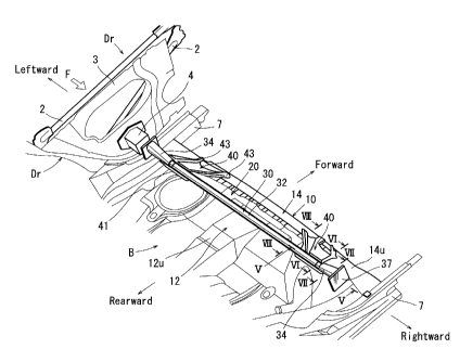
stepped
load receiving members 104 are disposed on an upper surface of a cross member
102
constituting a vehicle cabin floor 102f and are secured to both side portions
of the cross
member 102 in a vehicle widthwise direction. Each of the load receiving
members 104 is
constructed to receive a load at an end surface 104f thereof. The end surface
104f is
positioned opposite to a door box 103 of a rear door (not shown) in the
vehicle widthwise
direction. Therefore, when a collision load is applied to the vehicle rear
door from a lateral
side thereof, the collision load is transmitted to the end surface 104f of the
load receiving
member 104 via an impact beam 101 and the door box 103 of the rear door and is
transmitted
from the load receiving member 104 to the cross member 102. That is, the
vehicle rear door
can be supported by the load receiving member 104 and the cross member 102.
Thus, the
rear door can be prevented from protruding into a vehicle cabin.
[0003]
Patent Document 1: Japanese Laid-Open Patent Application No. 2007-22485
DISCLOSURE OF THE INVENTION
PROBLEM TO BE SOLVED BY THE INVENTION
[0004]
In the body structure described above, the stepped load receiving members 104
are
disposed on the upper surface of the cross member 102 and are secured to both
side portions
of the cross member 102 in the vehicle widthwise direction. Therefore, the
collision load F
1
CA 02699493 2010-03-11
that is transmitted to a body via the impact beam 101 and the door box 103 of,
for example,
the left rear door, can be concentrated to a left end portion of the cross
member 102 to which
the load receiving member 104 is secured. Therefore, it is necessary to
reinforce the cross
member 102 by, for example, thickening the same. As a result, costs required
to reinforce
the cross member 102 can be increased.
Further, because the load receiving members 104 are secured to both side
portions of
the cross member 102 in the vehicle widthwise direction, when, for example,
the cross
member 102 and the door box 103 are not aligned with each other in a vehicle
longitudinal
direction depending on vehicle models, it is necessary to manufacture the
different-shaped
load receiving members 104 for every vehicle models. This may lead to
increased
manufacturing costs of the load receiving members 104.
[0005] -
The present invention has been made in order to solve the above-mentioned
problems. It is an object of the present invention to prevent a vehicle door
from protruding
into a vehicle cabin when a collision load is applied to the door from a
lateral side thereof,
and to reduce costs that are required for measures to prevent the door from
protruding into the
vehicle cabin.
MEANS FOR SOLVING THE PROBLEM
[0006]
The above-mentioned problems can be solved by the invention of each of the
claims.
The invention described in claim 1 provides a vehicle body structure in which
a
collision load applied to one of vehicle doors from a lateral side thereof is
received by a load
receiving member of a body via an impact beam and a door box of the door and
is transmitted
from the load receiving member to a cross member. The load receiving member
includes a
load receiving pipe that is formed as a linear tubular body disposed between
the right and left
doors so as to extend in a vehicle widthwise direction and is capable of
transmitting the
collision load from the door box of one of the doors to a door box of the
other of the doors,
and connecting portions that are capable of supporting the load receiving pipe
at positions
adjacent to the right and left doors and coiuiecting the load receiving pipe
to the cross
member.
[0007]
According to the present invention, the collision load applied to the load
receiving
2
CA 02699493 2010-03-11
member via the impact beam and the door box of the door is transmitted from
the load
receiving pipe to the cross member via the connecting portions, and at the
same time, is
transmitted to the door box of the opposite door via the load receiving pipe.
That is, when
the collision load is applied to the vehicle door from the lateral side
thereof, the door is
supported by the cross member via the load receiving pipe and the connecting
portions, and at
the same time, is supported by the opposite door via the load receiving pipe.
Thus, the door
can be restricted from protruding into a vehicle cabin.
Further, the collision load is distributed to a load component (a transmission
load)
that can be transmitted from the load receiving pipe to the cross member and
can be received
by the cross member, and a load component (an axial load) that can be axially
applied to the
load receiving pipe and can be received by the load receiving pipe and the
opposite door.
Thus, because the collision load is distributed, the load component (the
transmission load)
applied to the cross member can be reduced. As a result, it is possible to
reduce
reinforcement of the cross member for measures to prevent the door from
protruding into the
vehicle cabin.
Further, in the load receiving member, the load receiving pipe is connected to
the
cross member via the connecting portions. Therefore, the load receiving member
can be
previously prepared and can be attached to the cross member in subsequent
processes. As a
result, the load receiving member can be commoditized in different vehicle
models.
Thus, it is possible to reduce costs that are required for measures to prevent
the door
from protruding into the vehicle cabin.
[0008]
In the invention described in claim 2, each of axial end portions of the load
receiving
pipe has a cone shape that is flared toward a distal end thereof.
Therefore, a directional change of the collision load caused by height-
variation of a
vehicle can be effectively compensated.
In the invention described in claim 3, the connecting portions are
respectively
independently disposed in one and the other sides in the vehicle widthwise
direction. Each
of the connecting portions includes an upper fixture portion to which the load
receiving pipe
is secured, and a lower fixture portion which is secured to the cross member.
The lower
fixture portion has a width greater than the upper fixture portion in the
vehicle widthwise
direction and is positioned inside of the upper fixture portion in the vehicle
widthwise
direction.
3
CA 02699493 2010-03-11
Therefore, each of the connecting portions can have an increased strength that
is
capable of axially supporting the load receiving pipe. As a result, the load
receiving pipe
cannot be easily moved axially by the collision load.
[0009]
In the invention described in claim 4, the door box has a receiving surface to
which
the impact beam subjected to the collision load can be pressed. The receiving
surface has a
hook-like projection that is capable of preventing the impact beam pressed to
the receiving
surface from being disengaged from the receiving surface.
Thus, the impact beam can be prevented from being disengaged from the
receiving
surface of the door box by impact of collision. Therefore, the collision load
can be reliably
transmitted to the door box.
[0010]
In the invention described in claim 5, the door box has a receiving surface to
which
the impact beam subjected to the collision load can be pressed. The receiving
surface
includes a front side inclined surface that is capable of transforming the
collision load from
the impact beam applied from diagonally before to a collision load which is
directed in the
vehicle widthwise direction, and a rear side inclined surface that is capable
of transforming
the collision load from the impact beam applied from diagonally behind to the
collision load
which is directed in the vehicle widthwise direction.
According to this structure, even when the collision load is applied to the
receiving
surface of the door box from diagonally before or diagonally behind via the
impact beam as a
result of deformation of, for example, the rear door by the collision, the
collision load can be
transformed to the collision load which is directed in the vehicle widthwise
direction, so as to
be efficiently transmitted to the load receiving pipe.
[0011]
In the invention described in claim 6, the door box is attached to a door
inner panel
constituting the door while the door box is inserted into an opening formed in
the door inner
panel. The door box has a hook portion that is formed in an upper surface
thereof and is
capable of engaging a periphery of the opening of the door inner panel when
the door box is
subjected to the collision load and is displaced toward a vehicle cabin.
According to this structure, when the door box subjected to the collision load
is
displaced toward the vehicle cabin, the hook portion formed in the upper
surface of the door
box can engage the periphery of the opening of the door inner panel.
Therefore, the door
4
CA 02699493 2010-03-11
ti
box can be prevented from rotating downwardly. As a result, an unfavorable
condition in
which the door box cannot contact the load receiving pipe can be avoided.
EFFECTS OF THE INVENTION
[0012]
According to the present invention, it is possible to prevent a vehicle door
from
protruding into a vehicle cabin when a collision load is applied to the door
from a lateral side
thereof, and to reduce costs that is required for measures to prevent the door
from protruding
into the vehicle cabin.
BRIEF DESCRIPTION OF THE DRAWINGS
[0013]
FIG 1 is a perspective view (figure A) of a load receiving member used in a
vehicle
body structure according to Embodiment 1 of the present invention, and an
exploded
perspective view (figure B) of an end portion of a load receiving pipe of the
load receiving
member.
FIG 2 is a vertical cross-sectional view of the vehicle body structure.
FIG 3 is an overall perspective view of the vehicle body structure, which is
viewed
from behind.
FIG 4 is an overall perspective view of the vehicle body structure, which is
viewed
from before.
FIG 5 is a cross-sectional view of a portion V in FIG 3 and FIG 4, which is
viewed
in the direction of arrows.
FIG 6 is a cross-sectional view of a portion VI in FIG 3 and FIG 4, which is
viewed
in the direction of arrows.
FIG 7 is a cross-sectional view of a portion VII in FIG 3 and FIG 4, which is
viewed
in the direction of arrows.
FIG 8 is a cross-sectional view of a portion VIII in FIG. 3 and FIG. 4, which
is
viewed in the direction of arrows.
FIG 9 is a side view of a door box and a load receiving pipe used in a vehicle
body
structure according to Embodiment 2 of the present invention, which
illustrates a positional
relation therebetween.
FIG 10 is a side view (figure A) of the door box, and an elevational view
thereof (a
CA 02699493 2010-03-11
view which is viewed in the direction of arrows B-B in figure A (figure B)).
FIG I1 is a side view (figure A) of a door box in a modified form, an
elevational
view thereof (a view which is viewed in the direction of arrows B-B in figure
A (figure B)),
and a plan view thereof (a view which is viewed in the direction of arrows C-C
in figure A
(figure Q.
FIG 12 is a perspective view of a conventional vehicle body structure.
DESCRIPTION OF SYMBOLS
[0014]
F ===== collision load
B ===== body
Dr ===== rear door
2 = = = impact beam
3 === door inner panel
3h ===opening
4 === door box
=== cross member
= = = = = load receiving member
..... load receiving pipe
32 === straight pipe portion
34 = = = flared portion
=== connecting portion
41 === recessed portion (upper connecting portion)
43 === bolt support portion (lower connecting portion)
60 === door box
64 = = = receiving surface
64x === front-side inclined surface
64y = = = rear-side inclined surface
66 = = = rib (projection)
67 = = = projection
69 === hook portion
BEST MODE FOR CARRYING OUT THE INVENTION
6
CA 02699493 2010-03-11
[0015]
In the following, a vehicle body structure according to Embodiment 1 of the
present
invention is described with reference to the drawings.
EMBODIMENT 1
[0016]
FIG 1 is an overall perspective view of a load receiving member used in a
vehicle
body structure according to the present embodiment, and an exploded
perspective view
thereo FIG 2 is a vertical cross-sectional view of the vehicle body
structure. FIG 3 and
FIG 4 are overall perspective views of the vehicle body structure. FIG 5 to
FIG 8 are
cross-sectional views of various portions in FIG 3 and FIG 4, which are viewed
in the
directions of arrows.
Further, in the drawings, forward and rearward, rightward and leftward, and
upward
and downward respectively correspond to forward and rearward, rightward and
leftward, and
upward and downward of a vehicle.
[0017]
<Regarding Outline of Vehicle Body Structure>
As shown in FIG 2, a vehicle body structure according to the present
embodiment is
intended to restrict a vehicle rear door Dr from protruding into a vehicle
cabin when a
collision load F is applied to the rear door Dr from a lateral side thereof.
As shown in, for example, FIG. 2, the rear door Dr includes a door outer panel
1 and
a door inner panel 3. Two impact beams 2 of high-tensile steel pipes are
disposed between
the panels 1 and 3, so as to extend rearward and forward. Further, a door box
4 is disposed
between the door outer panel 1 and the door inner panel 3. The door box 4 is
positioned to
receive the collision load F from the lower impact beam 2. Further, the door
box 4 is
positioned such that a portion thereof can project toward a vehicle cabin side
through the door
inner panel 3. In addition, the door inner panel 3 and the door box 4 are
covered by an
interior panel 5 in the vehicle cabin side.
In the vehicle body structure according to the present embodiment, as shown
in, for
example, FIG 2 and FIG. 3, the collision load F is received by the impact
beams 2 and the
door box 4 of the rear door Dr (the left rear door in FIG 2) and is
transtnitted to a load
receiving member 20 provided to a body B side. The collision load F is then
transmitted
from the load receiving member 20 to a cross member 10 and a door box and
other
components (not shown) of a right rear door.
7
CA 02699493 2010-03-11
That is, the left rear door Dr described above is supported by the cross
member 10
and the right rear door via the load receiving member 20 provided to the body
B side, so as to
be restricted from protruding into the vehicle cabin. Further, in FIG 2, the
cross member 10
is omitted.
[0018]
<Regarding Load Receiving Member 20>
The load receiving member 20 is a component that is capable of receiving the
collision load F transmitted from the door box 4 of the rear door Dr and
transmitting the
collision load F to the cross member 10 and the door box (not shown) of the
opposite rear
door. As shown in, for example, FIG 1(A), the load receiving member 20 is
composed of a
tubular load receiving pipe 30 and a pair of connecting portions 40. The
connecting portions
40 are capable of supporting both axial end portions of the load receiving
pipe 30 and
connecting the load receiving pipe 30 to the cross member 10.
As shown in FIG. 3 and FIG 4, the load receiving pipe 30 is disposed between
the
right and left rear doors Dr so as to extend in a vehicle widthwise direction.
The load
receiving pipe 30 has a length that is slightly smaller than the distance
between the right and
left rear doors Dr. Therefore, as shown in FIG 2, in a condition in which the
load receiving
pipe 30 is positioned between the right and left rear doors Dr, a space S is
formed between an
end surface of the load receiving pipe 30 and the interior panel 5 of the rear
door Dr.
As shown in FIG 1, the load receiving pipe 30 is composed of a straight pipe
portion
32 of a desired length of pipe, and flared portions 34 that are disposed in
both ends of the
straight pipe portion 32. Further, for example, a steel pipe of 30 mm in
diameter and 2 mm
in thickness is used as the straight pipe portion 32.
[0019]
As shown in, for example, FIG 1(B) and FIG 5, each of the flared portions 34
has a
cone shape that is flared toward a distal end thereof and has a rectangular
shape in cross
section. The flared portion 34 is constructed of an upper flared element 35
having a U-shape
in cross section, a lower flared element 36 having a U-shape in cross section,
and a
rectangular vertical flat plate 37. The upper flared element 35 and the lower
flared element
36 respectively constitute an upper half and a lower half of the flared
portion 34. Further,
the vertical flat plate 37 constitutes a distal end surface of the flared
portion 34 (the end
surface of the load receiving pipe 30). Further, half-cylindrical portions 35e
and 36e are
respectively formed in proximal ends (ends opposite to the distal end surface)
of the upper
8
CA 02699493 2010-03-11
= flared element 35 and the lower flared element 36, so as to receive the
straight pipe portion 32
between the half-cylindrical portions 35e and 36e. As shown in FIG 5, the
straight pipe
portion 32 is inserted into the flared portion 34 until an end surface thereof
contacts an inner
surface of the vertical flat plate 37. In this condition, an outer
circumferential surface of the
straight pipe portion 32 is bonded to the half-cylindrical portions 35e and
36e of the upper
flared element 35 and the lower flared element 36 by welding. Further, the
flared portion 34
is formed of, for example, a steel plate having a thickness of about 2 mm.
[0020]
As shown in FIG 1(A) and FIG 6 (a cross-sectional view of a portion VI in
FIGS. 3
and 4, which is viewed in the direction of arrows), each of the connecting
portions 40 is
formed as a substantially mountain-shaped plate body, and has a half-
cylindrical recessed
portion 41 that is formed in a ridge portion thereof. The recessed portion 41
of the
connecting portion 40 is a portion that is capable of supporting the straight
pipe portion 32
positioned adjacent to the flared portion 34 of the load receiving pipe 30
from below. The
recessed portion 41 is bonded to the straight pipe portion 32 by welding or
other such
methods.
Further, as shown in FIG. 1(B) and FIG 6, bolt receiving portions 43 are
formed in
the connecting portion 40. The bolt receiving portions 43 are formed in a foot
portion of the
substantially mountain-shaped plate body, so as to be positioned in two
portions in the vehicle
widthwise direction. The bolt receiving portions 43 of the connecting portion
40 are secured
to an upper surface 14u of the cross member 10 by bolting. Further, the
connecting portion
40 is formed of, for example, a steel plate having a thickness of about 2 mm.
As shown in FIG 6, the recessed portion 41 of the connecting portion 40 is
positioned behind the bolt receiving portions 43 at a constant distance L and
above the bolt
receiving portions 43 at a constant distance H. That is, when the bolt
receiving portions 43
of the connecting portion 40 are secured to the upper surface 14u of the cross
member 10, the
load receiving pipe 30 is positioned behind the cross member 10 at the
distance L and above
the cross member 10 at the distance H. Further, the distance L and the
distance H are
determined such that the load receiving pipe 30 is coincide with the door box
4 of the rear
door Dr in vehicle longitudinal and vertical directions.
Further, a distance between the bolt receiving portions 43 of the connecting
portion
40 in the vehicle widthwise direction is specified to be greater than the
axial length of the
recessed portion 41. In addition, the bolt receiving portions 43 are
positioned inside of the
9
CA 02699493 2010-03-11
= recessed portion 41 in the vehicle widthwise direction.
The ridge portion of the connecting portion 40 having the recessed portion 41
corresponds to an upper fixture portion. Conversely, the foot portion of the
connecting
portion 40 having the bolt receiving portions 43 corresponds to a lower
fixture portion.
[0021]
<Regarding Cross Member 10>
As shown in FIG 6 and FIG. 8 (a cross-sectional view of a portion VIII in
FIGS. 3
and 4, which is viewed in the direction of arrows), the cross member 10 to
which the bolt
receiving portions 43 of the connecting portions 40 are bolted is constructed
of a vehicle
cabin rear floor 12 and a front formed panel 14. The vehicle cabin rear floor
12 is a step-like
portion formed in a rear portion of the vehicle cabin. Conversely, the front
formed panel 14
covers a vertical portion 12f of the vehicle cabin rear floor 12 and has a
substantially reversed
L-shape in cross section.
As shown in FIG 6 and FIG 8, the front formed panel 14 includes an upper
flange
14f formed in an upper rear end periphery thereof and a lower flange 14d
formed in a lower
front end periphery thereof. The upper flange 14f of the front formed panel 14
is bonded to
an upper surface 12u of the vehicle cabin rear floor 12 by, for example,
welding. Conversely,
the lower flange 14d of the front formed panel 14 is bonded to a lower surface
12b of the
vehicle cabin rear floor 12 by, for example, welding. Thus, the closed box-
like hollow cross
member 10 is formed. The cross member 10 has a substantially rectangular cross-
sectional
shape and extends horizontally in the vehicle widthwise direction. Both end
portions of the
cross member 10 are connected to rockers 7 (FIG. 3) that are disposed in both
sides of the
body B.
Reinforcement plates 15 are attached to the front formed panel 14 constituting
the
cross member 10. The reinforcement plates 15 are positioned on rear surfaces
of portions to
which the bolt receiving portions 43 of the connecting portions 40 are bolted.
[0022]
<Regarding Vehicle Cabin Rear Floor 12 >
The load receiving member 20 is attached to the upper surface 12u of the
vehicle
cabin rear floor 12 and the upper surface 14u of the cross member 10.
Thereafter, a rear seat
9 (FIG 2) is disposed thereon.
As described above, because the load receiving pipe 30 of the load receiving
member
20 is positioned behind the cross member 10 at the distance L and above the
cross member 10
CA 02699493 2010-03-11
at the distance H, the load receiving pipe 30 is positioned above the upper
surface 12u of the
vehicle cabin rear floor 12. Consequently, as shown in FIG 5 and FIG. 7,
support bases 51
and support cradles 53 are disposed on the upper surface 12u of the vehicle
cabin rear floor 12
in order to support the straight pipe portion 32 of the load receiving pipe
30. The support
bases 51 and the support cradles 53 are positioned directly below the load
receiving pipe 30
and closer to the recessed portions 41 of the connecting portions 40. Further,
FIG 5 is a
cross-sectional view of a portion V in FIG 3 and FIG 4, which is viewed in the
direction of
arrows. FIG 7 is a cross-sectional view of a portion VII in FIG. 3 and FIG 4,
which is
viewed in the direction of arrows.
[0023]
<Regarding Attaching Operation of Load Receiving Member 20>
As shown in FIG 1(A), the load receiving member 20 is attached to the body B
while
the connecting portions 40 are connected to both end portions of the load
receiving pipe 30.
In other words, the bolt receiving portions 43 of each of the connecting
portions 40 are bolted
on the upper surface 14u of the cross member 10, so that the load receiving
member 20 can be
connected to the cross member 10. Further, the straight pipe portion 32 of the
load receiving
pipe 30 is supported on the support bases 51 and the support cradles 53
disposed on the upper
surface 12u of the vehicle cabin rear floor 12. The straight pipe portion 32
is secured to the
support cradles 53 by, for example, welding. Thus, as shown in FIG. 3 and FIG
4, an
attaching operation of the load receiving member 20 to the body B is
completed.
Next, the rear seat 9 is disposed on the upper surface 12u of the vehicle
cabin rear
floor 12. As a result, as shown in FIG 2, the load receiving member 20 can be
covered by
the rear seat 9. At this time, the end surfaces of the load receiving pipe 30
of the load
receiving member 20 can be covered by side wall portions 9e of the rear seat
9.
[0024]
<Regarding Function of Vehicle Body Structure According to Present Embodiment>
As shown in FIG 2, when the collision load F is applied to the vehicle left
rear door
Dr having the vehicle body structure according to the present embodiment from
a left-lateral
side thereof, the collision load F is transmitted to the door box 4 via the
impact beams 2 of the
rear door Dr. The collision load F is then transmitted from the door box 4 to
a left end
surface of the load receiving pipe 30 of the load receiving member 20.
Further, because the
flared portion 34 having the cone shape is disposed in the each end portion of
the load
receiving pipe 30, a directional change of the collision load F can be
effectively compensated.
11
CA 02699493 2010-03-11
The collision load F applied to the left end surface of the load receiving
pipe 30
axially presses the load receiving pipe 30 and is transmitted to the cross
member 10 via both
of the connecting portions 40. Further, the collision load F axially presses
the load receiving
pipe 30 and is transmitted to the door box and impact beams of the right rear
door Dr (not
shown). That is, the door box 4 and other components of the left rear door Dr
can be
supported by the both end portions of the cross member 10 via the load
receiving pipe 30 and
the connecting portions 40, and at the same time, can be supported by the door
box and other
components of the right rear door Dr (not shown) via the load receiving pipe
30. Thus, as
shown in FIG 2, even when the collision load F is applied to the vehicle left
rear door Dr
from the left-lateral side thereof, the left rear door Dr can be restricted
from protruding into
the vehicle cabin.
[0025]
<Regarding Advantages of Vehicle Body Structure>
In the vehicle body structure according to the present embodiment, the
collision load
F is distributed to a load component (a transmission load) that can be
transmitted from the
load receiving pipe 30 to the cross member 10 via the connecting portions 40
and can be
received by the cross member 10, and a load component (an axial load) that can
be axially
applied to the load receiving pipe 30 and can be received by the load
receiving pipe 30 and
the opposite (right) door. Thus, because the collision load F is distributed ,
the load
component (the transmission load) applied to the cross member 10 can be
reduced. As a
result, it is possible to reduce reinforcement of the cross member 10 for
measures to prevent
the door from protruding into the vehicle cabin.
Further, in the load receiving member 20, the load receiving pipe 30 is
connected to
the cross member 10 via the connecting portions 40. Therefore, the load
receiving member
20 can be previously prepared, so as to be attached to the cross member 10 in
subsequent
processes. As a result, the load receiving member 20 can be commoditized in
different
vehicle models.
Thus, it is possible to reduce costs that are required for measures to prevent
the rear
door Dr from protruding into the vehicle cabin.
[0026]
Further, because each of the axial end portions of the load receiving pipe 30
has a
cone shape that is flared toward a distal end thereof, the directional change
of the collision
load F caused by height-variation of the vehicle can be effectively
compensated.
12
CA 02699493 2010-03-11
Further, each of the connecting portions 40 includes the upper fixture portion
(the
ridge portion having the recessed portion 41) to which the load receiving pipe
30 is secured,
and the lower fixture portion (the foot portion having the bolt receiving
portions 43) which is
secured to the cross member 10. The lower fixture portion has a width greater
than the
upper fixture portion in the vehicle widthwise direction. In addition, the
lower fixture
portion is positioned inside of the upper fixture portion in the vehicle
widthwise direction.
Therefore, the connecting portion 40 can have an increased strength that is
capable of axially
supporting the load receiving pipe 30. As a result, the load receiving pipe 30
cannot be
easily moved axially by the collision load F.
[0027]
<Modified Forms>
The present invention is not limited to the embodiment described above and the
invention can be modified without departing from the scope thereof. For
example, in this
embodiment, the axial end portions of the load receiving pipe 30 are supported
by a pair of
connecting portions 40. However, the number of the connecting portions 40 can
be
increased, so as to additionally support the load receiving pipe 30, for
example, a central
portion thereof, by the connecting portion 40.
Further, in this embodiment, each of the flared portions 34 of the load
receiving pipe
30 has a cone shape and has a rectangular shape in cross section. However,
each of the
flared portions 34 may have various shapes in cross section
Further, in this embodiment, the bolt receiving portions 43 of the connecting
portions
40 are bolted to the cross member 10. However, the connecting portions can be
secured
thereto by, for example, welding.
[0028]
In the following, a vehicle body structure according to Embodiment 2 of the
present
invention is described with reference to the drawings.
EMBODIMENT 2
[0029]
In the vehicle body structure according to the present embodiment, the door
box 4
used in the vehicle body structure according to Embodiment 1 is modified.
Remaining
structures thereof are identical with the vehicle body structure according to
Embodiment 1.
Therefore, the same elements as the vehicle body structure according to
Embodiment 1 will
be identified by the same reference numerals and a detailed description of
such elements will
13
CA 02699493 2010-03-11
be omitted.
Further, FIG 9 is a side view of a door box 60 and a load receiving pipe 30
according
to the present embodiment, which illustrates a positional relation
therebetween. FIG 10 is a
side view (figure A) of the door box 60, and an elevational view thereof (a
view which is
viewed in the direction of arrows B-B in figure A (figure B)). FIG I 1 is a
side view (figure
A) of the door box 60 in a modified form, an elevational view thereof (a view
which is
viewed in the direction of arrows B-B in figure A (figure B)), and a plan view
thereof (a view
which is viewed in the direction of arrows C-C in figure A (figure Q.
[0030]
The door box 60 is a box-shaped member that is capable transmitting the
collision
load F applied from the impact beams 2 to the load receiving pipe 30. As shown
in FIG 9
and 10(A), the door box 60 includes a vehicle cabin-side box 61 that projects
toward the
vehicle cabin side through the door inner panel 3, and an inside box 63 that
is positioned
inside of the rear door Dr. The vehicle cabin-side box 61 and the inside box
63 are
respectively formed as box-shaped members having openings. The vehicle cabin-
side box
61 and the inside box 63 respectively have flange portions 61f and 63f that
are formed along
peripheries of the openings. The flange portion 61 f of the vehicle cabin-side
box 61 and the
flange portion 63f of the inside box 63 are bonded to each other, thereby
forming the door box
60. Further, the inside box 63 is inserted into an opening 3h formed in the
door inner panel 3
and the flange portions 61 f and 63 f are bolted to the door inner panel 3
along a periphery of
the opening 3h. Thus, the door box 60 is secured to the door inner panel 3.
[0031]
The inside box 63 of the door box 60 has a receiving surface 64 to which the
impact
beam 2 is pressed when the collision load F is applied to the rear door Dr.
The receiving
surface 64 is formed in a distal end side (a side opposite to the flange
portion 63f) of the
inside box 63. Further, the receiving surface 64 has a longitudinally
extending rib 66 that is
formed in a lower portion thereof. Therefore, the impact beam 2 can be
prevented from
being disengaged from the receiving surface 64 of the door box 60 downwardly
by impact of
collision. Further, the receiving surface 64 of the door box 60 has a hook-
like projection 67
that is formed in an upper portion thereof, so as to prevent the impact beam 2
from being
disengaged from the receiving surface 64 upwardly.
Thus, due to the effects of the rib 66 and the projection 67, the impact beam
2 can be
prevented from being disengaged from the receiving surface 64 of the door box
60 by the
14
CA 02699493 2010-03-11
impact of collision. Therefore, the collision load F can be reliably
transmitted from the
impact beam 2 to the door box 60.
Further, the vehicle cabin-side box 61 of the door box 60 has a contact
surface 61x
which is pressed to the load receiving pipe 30 when the collision load F is
applied to the door
box 60. The contact surface 61x is formed in a distal end side (a side
opposite to the flange
portion 61 f) of the vehicle cabin-side box 61.
[0032]
<Modified Forms>
The present invention is not limited to the embodiment described above and the
invention can be modified without departing from the scope thereof. For
example, in this
embodiment, the receiving surface 64 is formed as a flattened surface.
However, as the plan
view of FIG 11(C), the receiving surface 64 can be formed as an angled surface
having a
front side inclined surface 64x that is directed diagonally forwardly and a
rear side inclined
surface 64y that is directed diagonally rearwardly. According to this
structure, even when
the impact beam 2 collides against the receiving surface 64 of the door box 60
from
diagonally before or diagonally behind as a result of deformation of, for
example, the rear
door Dr, the collision load F applied from diagonally can be transformed to a
collision load
Fw which is directed in the vehicle widthwise direction, so as to be
efficiently transmitted to
the load receiving pipe 30.
Further, as shown in, for example, FIG 11(A), the inside box 63 of the door
box 60
has a hook portion 69 that is formed in an upper surface 63u thereof and is
capable of
engaging the periphery of the opening 3h of the door inner panel 3. According
to this
structure, when the door box 60 subjected to the collision load F is displaced
toward the
vehicle cabin, the hook portion 69 formed in the upper surface 63u of the door
box 60 can
engage the periphery of the opening 3h of the door inner panel 3. Therefore,
the door box 60
subjected to the collision load F can be prevented from rotating downwardly.
As a result, an
unfavorable condition in which the door box 60 cannot contact the load
receiving pipe 30 can
be avoided.
Further, the door box 60 shown in FIG 11 can have the hook-like projection 67
shown in FIG 10 that is formed in the upper portion of the receiving surface
64.