Language selection

Search

Patent 2699556 Summary

Third-party information liability

Some of the information on this Web page has been provided by external sources. The Government of Canada is not responsible for the accuracy, reliability or currency of the information supplied by external sources. Users wishing to rely upon this information should consult directly with the source of the information. Content provided by external sources is not subject to official languages, privacy and accessibility requirements.

Claims and Abstract availability

Any discrepancies in the text and image of the Claims and Abstract are due to differing posting times. Text of the Claims and Abstract are posted:

  • At the time the application is open to public inspection;
  • At the time of issue of the patent (grant).
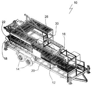
(12) Patent: (11) CA 2699556
(54) English Title: MOBILE ELEVATING WORK PLATFORM
(54) French Title: NACELLE ELEVATRICE DE TRAVAIL MOBILE
Status: Granted
Bibliographic Data
(51) International Patent Classification (IPC):
  • B66F 11/04 (2006.01)
  • B66B 9/16 (2006.01)
  • B66F 7/02 (2006.01)
(72) Inventors :
  • EARL, JOSEPH L.J. (Canada)
  • SAMUEL, THOMAS J. (Canada)
(73) Owners :
  • ENERGERA INC. (Canada)
(71) Applicants :
  • EARL, JOSEPH L.J. (Canada)
  • SAMUEL, THOMAS J. (Canada)
(74) Agent: LAMBERT INTELLECTUAL PROPERTY LAW
(74) Associate agent:
(45) Issued: 2012-03-13
(22) Filed Date: 2010-04-15
(41) Open to Public Inspection: 2011-05-11
Examination requested: 2010-12-21
Availability of licence: N/A
(25) Language of filing: English

Patent Cooperation Treaty (PCT): No

(30) Application Priority Data: None

Abstracts

English Abstract

There is provided a mobile height-adjustable platform that includes a chassis with ground engaging wheels. A mast is pivotally connected to the chassis and is movable between a transport position where the mast is parallel to and disposed over the chassis, and an operative position where the mast is perpendicular to the chassis and extends upwards. A conveyor moves along the mast and a work platform is pivotally connected to the conveyer. The work platform is movable between a transport position where the platform is parallel to the mast and an operating position where the platform is perpendicular to the mast.


French Abstract

La présente entrée porte sur une nacelle élévatrice de travail mobile et réglable en hauteur comprenant un châssis à roues en contract avec le sol. Un mât pivotant est fixé sur le châssis et peut être mis en position de transport, celui-ci étant alors parallèle au châssis et disposé par dessus celui-ci. En position de travail, le mât est perpendiculaire au châssis et s'étend vers le haut. Un convoyeur se déplace le long du mât et une nacelle de travail pivotante y est fixée. La nacelle en question peut être mise en position de transport, celle-ci étant alors parallèle au mât, ou en position de travail où elle est plutôt perpendiculaire au mât.

Claims

Note: Claims are shown in the official language in which they were submitted.


What is Claimed is:


1. A mobile height-adjustable platform, comprising:
a chassis having ground engaging wheels;
a mast pivotally connected toward an outer perimeter of the chassis, the mast
having a
transport position parallel to and disposed over the chassis and an operating
position
perpendicular to the chassis and extending upward;
a conveyor that moves along the mast;
a work platform connected to the conveyor by a pivotal connection, the pivotal

connection moving the work platform between a transport position parallel to
the mast and an
operating position perpendicular to the mast and extending outward from the
outer perimeter
of the chassis.

2. The mobile height-adjustable platform of claim 1, wherein, in the transport
position, an
upper surface of the work platform is adjacent to the mast.

3. The mobile height-adjustable platform of claim 2, comprising a safety
railing along at least
opposed sides of the work platform, the safety railing being separated by a
width that is
greater than a width of the mast, the mast nesting within the safety railing
in the transport
position.

4. The mobile height-adjustable platform of claim 3, further comprising
collapsible railing
sections attached to the work platform or the safety railing.

5. The mobile height-adjustable platform of claim 1, comprising a height-
adjustable ladder or
a height-adjustable staircase having a first end connected to the work
platform and a second
end adjacent to the chassis.

6. The mobile height-adjustable platform of claim 1, wherein the mast is
pivotally connected
to a rear edge of the chassis.

Description

Note: Descriptions are shown in the official language in which they were submitted.


CA 02699556 2010-04-15
TITLE
[0001] Mobile elevating work platform
FIELD
[0002] ['his rela'es to .,7t mobile elevating work platform.
BACKGROUND
[0003] U.S. patent no. 4,290,495 (Elliston) entitled "Portable workover rig
with
extendable mast substructure, platform mounted drawworks and adjustable
wellhead anchor"
describes a transportable mast that is used for workovers. A height-adjustable
platform is also
available from Colter Energy Services Inc. of Calgary, A13
(www.colterenergy.corn).

SUMMARY
[0004] There is provided a mobile height-adjustable platform that includes a
chassis with
ground engaging wheels. A mast is pivotally connected toward an outer
perimeter of the
chassis and is movable between a transport position where the mast is parallel
to and disposed
over the chassis, and an operative position where the mast is perpendicular to
the chassis and
extends upwards. A conveyor moves along the mast and a work platform is
pivotally
connected to the conveyer. The work platform is movable between a transport
position where
the platform is parallel to the mast and an operating position where the
platform is
perpendicular to the. mast and extends outwards front the outer perimeter of
the chassis. In the
transport position, an upper surface of the work platform may be adjacent to
the mast. the
mast maybe pivotally connected to a rear edge of the chassis.

[0005] According to another aspect, there may be a safety railing along at
least opposed
sides of the work platform, the safety railing being separated by a width that
is greater than a
width of the mast, the mast nesting within the safety railing in the transport
position. There
may be collapsible railing sections attached to the work platform or the
safety railing.

[0006] According to another aspect, there may be a height-adjustable ladder or
a height-
adjustable staircase havi ag a first end connected to the work platform and a
second end
adjacent to the chassis.


CA 02699556 2010-04-15
2

BRIEF DESCRIPTION OF THE DRAWINGS
[0007] These and other natures will become more apparent from the following
description in which reference is made to the appended drawings, the drawings
are for the
purpose of illustration only and are not intended to be in any way limiting,
wherein:
FIG. I iss a perspective view of a mobile elevating work platform in the
transport
position.
FIG. 2 is a perspective view of the mobile elevating work platform shown in
FIG.
1 in the operative position.
FIG. 3 is a side elevation view of the mobile elevating work platform shown in
FIG. 2 with the work platform at different heights.
FIG. 4 is a side elevation view of the mobile elevating work platform shown in
FIG. 2 with the work platform in the transport position
FIG. 5 is a top plan view of the mobile elevating work platform in the
transport
position.
FIG. 6 is a top plan view of the mobile elevating work platform in the
operative
position.

DETAILED DESCRIPTION
[0008] A mobile elevating work platform generally identified by reference
numeral 10,
will now be described with reference to FIG. 1 through 6.

Structure and Relationship of Parts:
[0009] Referring; to FIG. 1, a mobile height-adjustable platform 10 includes a
chassis 12
having ground engaging wheels 14. As shown, chassis 12 is a trailer that is
designed to be
pulled behind a. truck: (not shown). Referring to FIG. 5, a mast 16 is
pivotally connected at a
pivot point 18 at the rear edge 22 of chassis 12 and is movable between a
transport position
and an operating position. Rear edge 22 is preferred as allows mast 16 to be
folded along the
length of chassis 12, and can be more easily backed into place. Referring to
FIG. 1, in the
transport position, mast 1.6 is parallel to and disposed over chassis 12.
Referring to FIG. 2, in
the operating position. mast 16 is perpendicular to chassis 12 and extends
upward. A
conveyor 24 moves along the mast 16 to move a work platform 26. As shown, mast
16 has


CA 02699556 2010-04-15
3

parallel tracks 25 that conveyor 24 engages and moves along.. Conveyor 24 is
designed to
engage mast 16 in a manner that provides stability under expected loading
conditions and
during height adjustmrrenit. Conveyor 24 may be self-driven, such that it
moves itself along
tracks 25, or, more preferably, it may iae externally controlled, such as by a
winch (not shown)
or other means.

[0010] Work platfonn 26 is connected to conveyor 24 by a pivotal connection
28.
Referring to FIG. 6, pivotal. connection 28 also moves work platform 26
between a transport
position and an operating position. Referring to FIG. 1, in the transport
position, work
platform 26 is parallel to mast 16 such that the upper surface 30 of work
platform 26 is
adjacent to mast 16. or in other words, work platforms 26 is inverted.
Referring to FIG. 2, in
the operating position, work platform 26 is perpendicular to mast 16 and
extends outward
from outer perimeter 20 of chassis 12. As shown, a first end 38 of a height-
adjustable
staircase 40 is connected to work platform 26 and a second end 42 of staircase
40 is adjacent
to chassis 12. As pla.tfonn 26 is raised, staircase 40 raises along with it to
provide easy
access. The staircase 40 is designed such that, as one end is raised, the
individual stairs
remain horizontal. While staircase 40 is preferred for platform access and
safety reasons, it
will be understood that, in= toad of staircase 40, it could also be a ladder,
etc.

[0011] Referring to FIG. 2, there are safety railings 32. along the side 34 of
work platform
26 that are separated by a width that is greater than the width of mast 16 to
allow mast 16 to
nest within railings 32 in the transport position, as shown in FIG. 1.
Referring to FIG. 2,
collapsible railing wctien_ 36 may be attached to work platform 26 or safety
railings 32 to
allow the necessary,-no,,ti1 of separation. Referring to FIG. 2, railings 32
have openings 44
in front and may have an opening 46 on the side to provide greater
accessibility and
functionality. Wort: platform 26 also has an opening 48 on the floor to allow
platform 26 to
be positioned over and around a wellhead (not shown).

Operation:
[0012] Referrine to FIG. ii, mobile height-adjustable platform 10 is in the
transport
position. Mast 16 is aeral~Icl to and disposed over chassis 12 and work
platform 26 is parallel


CA 02699556 2011-11-04
4

to mast 16. Referring to FIG. 4, mast 16 is pivotally rotated about pivot
connection 18 to the
operating position such that it is perpendicular to chassis 12 and extends
upwards away from
chassis 12. Referring to FIG. 2 and 3, once mast 16 is raised, work platform
26 is pivoted
from the transport position into the operative position by pivoting work
platform 26 about
pivot connection 28. Platform 26 is then perpendicular to and extends outwards
from mast
16. Platform 26 will generally be in the lower position shown in FIG. 3 at
this point, and will
be positioned with floor opening positioned over the wellhead (not shown).
Once raised,
railing 32 is prepared for use by installing collapsible railing sections 36
to provide a safe
working environment. Conveyor 24 can then be used to move work platform 26 up
and down
the length of mast 16. Referring to FIG. 3, a height-adjustable staircase 40
allows access to
work platform 26 from chassis 12.

[0013] In this patent document, the word "comprising" is used in its non-
limiting sense to
mean that items following the word are included, but items not specifically
mentioned are not
excluded. A reference to an element by the indefinite article "a" does not
exclude the
possibility that more than one of the element is present, unless the context
clearly requires that
there be one and only one of the elements.

[0014] The following claims are to be understood to include what is
specifically illustrated
and described above, what is conceptually equivalent, and what can be
obviously substituted.
The scope of the claims should not be limited by the preferred embodiments set
forth in the
examples, but should be given the broadest interpretation consistent with the
description as a
whole.

Representative Drawing
A single figure which represents the drawing illustrating the invention.
Administrative Status

For a clearer understanding of the status of the application/patent presented on this page, the site Disclaimer , as well as the definitions for Patent , Administrative Status , Maintenance Fee  and Payment History  should be consulted.

Administrative Status

Title Date
Forecasted Issue Date 2012-03-13
(22) Filed 2010-04-15
Examination Requested 2010-12-21
(41) Open to Public Inspection 2011-05-11
(45) Issued 2012-03-13
Re-examination Certificate 2018-06-15

Abandonment History

There is no abandonment history.

Maintenance Fee

Last Payment of $125.00 was received on 2024-02-02


 Upcoming maintenance fee amounts

Description Date Amount
Next Payment if standard fee 2025-04-15 $624.00
Next Payment if small entity fee 2025-04-15 $253.00

Note : If the full payment has not been received on or before the date indicated, a further fee may be required which may be one of the following

  • the reinstatement fee;
  • the late payment fee; or
  • additional fee to reverse deemed expiry.

Patent fees are adjusted on the 1st of January every year. The amounts above are the current amounts if received by December 31 of the current year.
Please refer to the CIPO Patent Fees web page to see all current fee amounts.

Payment History

Fee Type Anniversary Year Due Date Amount Paid Paid Date
Application Fee $200.00 2010-04-15
Registration of a document - section 124 $100.00 2010-11-02
Advance an application for a patent out of its routine order $500.00 2010-12-21
Request for Examination $400.00 2010-12-21
Final Fee $300.00 2011-12-20
Maintenance Fee - Application - New Act 2 2012-04-16 $50.00 2012-01-27
Maintenance Fee - Patent - New Act 3 2013-04-15 $50.00 2013-02-06
Maintenance Fee - Patent - New Act 4 2014-04-15 $50.00 2014-02-03
Maintenance Fee - Patent - New Act 5 2015-04-15 $100.00 2015-02-03
Maintenance Fee - Patent - New Act 6 2016-04-15 $100.00 2016-02-02
Registration of a document - section 124 $100.00 2017-02-14
Maintenance Fee - Patent - New Act 7 2017-04-18 $100.00 2017-04-12
Re-Examination requested - Standard $2,000.00 2017-10-17
Maintenance Fee - Patent - New Act 8 2018-04-16 $100.00 2017-12-22
Registration of a document - section 124 $100.00 2018-06-19
Maintenance Fee - Patent - New Act 9 2019-04-15 $100.00 2019-02-15
Registration of a document - section 124 $100.00 2019-08-20
Maintenance Fee - Patent - New Act 10 2020-04-15 $125.00 2020-01-31
Maintenance Fee - Patent - New Act 11 2021-04-15 $125.00 2021-04-09
Registration of a document - section 124 $100.00 2021-09-29
Maintenance Fee - Patent - New Act 12 2022-04-15 $125.00 2022-02-17
Maintenance Fee - Patent - New Act 13 2023-04-17 $125.00 2023-03-06
Maintenance Fee - Patent - New Act 14 2024-04-15 $125.00 2024-02-02
Owners on Record

Note: Records showing the ownership history in alphabetical order.

Current Owners on Record
ENERGERA INC.
Past Owners on Record
EARL, JOSEPH L.J.
FRAC SHACK INC.
RIGLESS RENTALS INC.
SAMUEL, THOMAS J.
Past Owners that do not appear in the "Owners on Record" listing will appear in other documentation within the application.
Documents

To view selected files, please enter reCAPTCHA code :


To view images, click a link in the Document Description column. To download the documents, select one or more checkboxes in the first column and then click the "Download Selected in PDF format (Zip Archive)" or the "Download Selected as Single PDF" button.

List of published and non-published patent-specific documents on the CPD .

If you have any difficulty accessing content, you can call the Client Service Centre at 1-866-997-1936 or send them an e-mail at CIPO Client Service Centre.


Document
Description 
Date
(yyyy-mm-dd) 
Number of pages   Size of Image (KB) 
Maintenance Fee Payment 2020-01-31 1 33
Maintenance Fee Payment 2021-04-09 1 33
Representative Drawing 2011-04-14 1 74
Cover Page 2011-04-14 2 126
Maintenance Fee Payment 2022-02-17 1 33
Maintenance Fee Payment 2023-03-06 1 33
Abstract 2010-04-15 1 16
Description 2010-04-15 4 188
Claims 2010-04-15 1 39
Drawings 2010-04-15 5 475
Description 2011-11-04 4 181
Claims 2011-11-04 1 36
Cover Page 2012-02-15 1 101
Correspondence 2011-03-31 3 159
Prosecution-Amendment 2010-12-21 2 107
Correspondence 2011-03-09 2 108
Correspondence 2011-04-26 1 17
Correspondence 2011-04-26 1 22
Re-examination request filed. Small Entity Declar. 2017-10-17 25 1,428
Assignment 2010-04-15 2 86
PAB Letter 2017-11-21 1 42
Correspondence 2011-02-28 1 33
Maintenance Fee Payment 2017-12-22 1 33
PAB Letter 2018-01-12 7 311
Re-examination request filed. Small Entity Declar. 2018-04-12 7 193
Cover Page 2018-06-08 2 108
PAB Letter 2018-06-15 12 720
Cover Page 2018-06-15 15 943
Correspondence 2010-05-11 1 44
Assignment 2010-11-02 4 395
Correspondence 2010-11-16 1 23
Correspondence 2010-12-23 1 98
Correspondence 2011-02-28 1 24
Correspondence 2011-03-16 1 14
Correspondence 2011-03-16 1 20
Maintenance Fee Payment 2019-02-15 1 33
Prosecution-Amendment 2011-10-06 1 14
Prosecution-Amendment 2011-10-24 2 76
Prosecution-Amendment 2011-11-04 7 198
Correspondence 2011-12-20 1 35
Fees 2013-02-06 1 163
Maintenance Fee Payment 2024-02-02 1 33
Change of Agent 2017-03-01 2 56
Office Letter 2017-03-13 1 23
Change of Agent 2017-03-22 2 56
Office Letter 2017-04-03 1 22
Office Letter 2017-04-03 1 25
Maintenance Fee Payment 2017-04-12 1 33