Note: Descriptions are shown in the official language in which they were submitted.
CA 02699824 2010-03-16
WO 2009/054977 PCT/US2008/012026
BACKGROUND
[0001] Ozone is an unstable gas with a half-life of less than one hour at
room
temperature. Ozone is a powerful oxidizer. It is a known bactericide and
viricide.
Methods for.converting oxygen to ozone involve high-voltage corona discharge
or
ultraviolet light. Ozone generators making use of such methods are available
for
industrial uses.
[0002] Ozone has a variety of industrial applications. Applications
include
deodorizing air, purifying water and sterilizing medical instruments, among
others.
Ozone and conventional medical ozone generators are being used therapeutically
in
many countries and have been so for several years. Such applications include,
but are
not limited to, autohemotherapy, rectal insufflations, intradiscal injection,
injection into
knee and shoulder joints, and full body exposure.
[0003] For example, ozone is used to treat diffuse bulging or contained
herniation
of the spinal disc. Spinal discs are composed of a fibrous outer ring made of
Type I
collagen and a softer more flexible nucleus made of Type 11 collagen,
proteoglycans and
water. Patients with disc bulging or herniation suffer from pain caused by
disc
compression of the neurological elements, including the spinal cord, cauda
equina and
nerve roots. Intradiscal ozone treatment involves direct injection of a
gaseous mixture
of oxygen and ozone into the nucleus of the disc. Ozone releases water from
the
proteoglycans, reducing disc size and relieving compression of neurological
elements.
Some investigators believe that ozone stimulates anti-inflammatory mediators
and
initiates a healing response.
- 1 -
SUBSTITUTE SHEET (RULE 261)
CA 02699824 2010-03-16
WO 2009/054977 PCT/US2008/012026
[0004] The mechanism of action and reported success rates of ozone
treatment
for spinal disc herniation are comparable to that of the enzyme chymopapain.
Chymopapain was first FDA-approved in 1983 and was widely used with a success
rate
of 65-85%. A small number of serious complications, including death and
paralysis,
caused the product to lose favor in the U.S. market.
[0005] Ozone and chymopapain are two means of performing a chemical
discectorny through a needle puncture. This minimally invasive approach may be
preferred to surgical discectomy, which requires general anesthesia and direct
access
to the spinal disc.
[0006] Therapeutic ozone must be delivered shortly after being produced
from
oxygen. Conventional medical ozone generators pass medical grade oxygen
through
an electric field or ultraviolet light. This process converts an amount of
oxygen into
ozone. Typically, a syringe is interfaced with the generator and ozone is
withdrawn
from a gas chamber of the generator into the syringe for subsequent injection
therapy.
[0007] The preferred concentration of ozone for intradiscal injection is
approximately 6%. The concentration of ozone is important for medical uses. If
the
concentration is too low, the treatment will not be effective. If the
concentration of
ozone is too high, detrimental effects may follow.
[0008] As such, medical ozone generators include a means for measuring
the
concentration of ozone. Conventional ozone generators also have means for
controlling
the concentration and delivery of ozone gas. For example, some generators
include
components that neutralize excess ozone. Other generators continuously vent
ozone.
- 2 -
CA 02699824 2010-03-16
WO 2009/054977 PCT/US2008/012026
[0009] Conventional ozone generators typically include permanent and
reusable
electrodes. The gas chambers of conventional generators are often permanent
and
reusable as well. Reusable electrodes tend to degrade over time. Sterility is
an issue
for present ozone generators that pass oxygen through permanent and reusable
gas
chambers. To address such, medical professionals have been known to inject the
gas
through a bacterial filter.
SUMMARY
[0010] According to at least one exemplary embodiment, a cell for
producing an
amount of ozone from oxygen is disclosed. The cell can have a syringe, which
can
have a gas chamber. One or more electrodes can be attached to the syringe. One
or
more electrical contact points can be outside the gas chamber. Each electrical
contact
point can be connected to an electrode.
[0011] In another exemplary embodiment, a method of producing an amount
of
ozone from oxygen is disclosed. The method can include providing oxygen gas
within a
gas chamber of a syringe and effectuating a corona discharge from at least one
electrode. The at least one electrode can be attached to the syringe. An
amount of
ozone gas can be produced from the oxygen gas.
[0012] In yet another exemplary embodiment, an ozone generation system is
disclosed. The ozone generation system can include a syringe. The syringe can
have
a gas chamber. One or more electrodes can be attached to the syringe. The
electrodes can be connected to electrical contact points. A medical ozone
generator
can be connected to the syringe via electrical contact points.
- 3 -
CA 02699824 2010-03-16
WO 2009/054977 PCT/US2008/012026
BRIEF DESCRIPTION OF THE FIGURES
[0013] Advantages of embodiments of the present invention will be
apparent from
the following detailed description of the exemplary embodiments thereof, which
description should be considered in conjunction with the accompanying drawings
in
which:
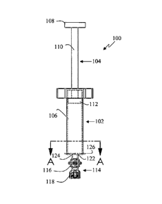
[0014] Fig. 1A is a side view of an exemplary syringe.
[0015] . Fig. 1B is a perspective view of an exemplary syringe.
[0016] Fig. 1C is another side view of an exemplary syringe.
[0017] Fig. 1D is a cross-sectional view along line A of Fig. 1A.
[0018] Fig. lE is an enlarged view of the portion circumscribed by line B
of Fig.
1B.
[0019] Fig. 2A is a side view of another exemplary syringe.
[0020] Fig. 2B is a perspective view of another exemplary syringe.
[0021] Fig. 2C is another side view of another exemplary syringe.
[0022] Fig. 2D is a cross-sectional view along line A of Fig. 2A.
[0023] Fig. 2E is an enlarged view of the portion circumscribed by line B
of Fig.
2B.
[0024] Fig. 3A is a side view of yet another exemplary syringe.
[0025] Fig. 3B is an inverted perspective view of yet another exemplary
syringe.
[0026] Fig. 3C is another side view of yet another exemplary syringe.
[0027] Fig. 3D is a cross-sectional view along line A of Fig. 3A.
- 4 -
CA 02699824 2010-03-16
WO 2009/054977 PCT/US2008/012026
[0028] Fig. 3E is an enlarged inverted view of the portion circumscribed
by line B
of Fig. 3B.
[0029] Fig. 4A is a side view of still another exemplary syringe.
[0030] Fig. 4B is an inverted perspective view of still another exemplary
syringe.
[0031] Fig. 4C is another side view of still another exemplary syringe.
[0032] Fig. 4D is a cross-sectional view along line A of Fig. 4A.
[0033] Fig. 4E is an enlarged inverted view of the portion circumscribed
by line B
of Fig. 4B.
[0034] Fig. 5A is a side view of a further exemplary syringe.
[0035] Fig. 5B is a perspective view of a further exemplary syringe.
[0036] Fig. 5C is another side view of a further exemplary syringe.
[0037] Fig. 5D is a cross-sectional view along line A of Fig. 5A.
[0038] Fig. 5E is an enlarged view of the portion circumscribed by line B
of Fig.
5B.
[0039] Fig. 5F is an enlarged view of the portion circumscribed by line C
of Fig.
5C.
[0040] Fig. 6A is a side view of still a further exemplary syringe.
[0041] Fig. 6B is a perspective view of still a further exemplary
syringe.
[0042] Fig. 6C is another side view of still a further exemplary syringe.
[0043] Fig. 6D is a cross-sectional view along line A of Fig. 6A.
[0044] Fig. 6E is an enlarged view of the portion circumscribed by line B
of Fig.
6B.
- 5 -
CA 02699824 2015-06-09
DETAILED DESCRIPTION
[0045] Aspects of the invention are disclosed in the following description
and
related drawings directed to specific embodiments of the invention. Alternate
embodiments may be devised. The scope of the claims should not be limited by
the preferred
embodiments set forth in the examples, but should be given the broadest
interpretation
consistent with the Description as a whole.
Additionally, well-known elements of exemplary embodiments of the
invention will not be described in detail or will be omitted so as not to
obscure the
relevant details of the invention. Further, to facilitate an understanding of
the
description discussion of several terms used herein follows.
[0046] The word "exemplary" is used herein to mean "serving as an example,
instance, or illustration." Any embodiment described herein as "exemplary" is
not
necessarily to be construed as preferred or advantageous over other
embodiments.
Likewise, the terms "embodiments of the invention", "embodiment" or
""invention" do not
require that all embodiments of the invention include the discussed feature,
advantage
or mode of operation.
[0047] Referring to Figs. 1A-1E, a syringe in accordance with at least one
exemplary embodiment is shown. Syringe 100 can be single-use and may be
reprocessable. Altematively, syringe 100 may be multi-use with sterilization,
although
such embodiments would stray from current trends in healthcare. Syringe 100
can be
fabricated, in whole or in part, by any conventional molding processes known
to one
having ordinary skill in the art. Syringe 100 can serve as a cell for
producing an amount
of ozone from oxygen when used with a suitable ozone conversion unit, as
further
described below. Syringe 100 can then be used to administer a therapeutic
amount of
- 6 -
CA 02699824 2010-03-16
WO 2009/054977 PCT/US2008/012026
ozone to a human or an animal as will be readily recognized by one having
ordinary skill
in the art.
[0048] Syringe 100 can include barrel 102, plunger 104 and gas chamber
106.
Gas chamber 106 can be defined and bounded through the cooperation of barrel
102
and plunger 104. In at least one exemplary embodiment, syringe 100 can be
sized to
hold between 10m1 and 30m1 of fluid in gas chamber 106, including between 10m1
and
30m1 of medical grade oxygen.
[0049] Barrel 102 can be made of any suitable material that allows for at
least
some UV transmission. This can allow for the passage of a UV beam through
barrel
102 and a gas within gas chamber 106 for measuring the concentration of ozone
gas.
=Furthermore, barrel 102 can be constructed of any material that sufficiently
balances the
needs for ozone resistance and UV resistance while still allowing for suitable
UV
transmission for measuring the concentration of ozone. Flexibility in
construction can
be increased because syringe embodiments may only be exposed to ozone and UV
light for a shortened / decreased period of time.
[0050] For example, barrel 102 (in which, syringe 100, as a whole, can be
constructed largely or wholly of the same) can be constructed of polyethylene,
polytetraflouroethylene ("PTTF", TEFLON ), polyacrylate (acrylic polymers),
polycarbonate, polystyrene, styrene copolymers, polypropylene and the like
known to
one having ordinary skill in the art. Barrel 102 can also be made of glass, as
one more
non-limiting example. In at least one exemplary embodiment, barrel 102 can be
made
of polyethylene even though polyethylene may only allow about 10% UV
transmission.
= - 7 -
CA 02699824 2010-03-16
WO 2009/054977 PCT/US2008/012026
A UV transmission of about 10% can be enough to measure ozone concentration
within
gas chamber 106 with suitable accuracy.
[0051] Plunger 104 can be slidably engaged with a first open end (i.e.
top end) of
barrel 102. The engagement of plunger 104 with barrel 102 can define the
bounds of
gas chamber 106 within syringe 100. Through sliding movements of plunger 104
within
barrel 102, a fluid, including a gaseous fluid (e.g., oxygen gas), can be
drawn into and
expelled from gas chamber 106. Plunger 104 can include a plunger head 108 on
one
end of plunger shaft 110. On the other end of plunger shaft 110 can be plunger
piston
112. Plunger piston 112 can form a gas-tight seal with barrel 102. Plunger
piston 112
may be made from or covered with rubber and the like known to one having
ordinary
skill in the art
[0052] Tip portion 114 can extend in fluid communication from a second
end of
barrel 102 under the control of valve 116. Valve 1_16 can be a stopcock valve,
as one
non-limiting example. Connector 118 can be situated at the distal end of tip
portion 114.
Connector 118 can be a luer fitting (e.g., press-on or twist-on) and the like
known to one
having ordinary skill in the art. For example, connector 118 can be a luer
lock fitting for
receiving a hypodermic needle for use in an ozone therapy.
[0053] Wire electrodes 120, 122 can extend inwardly within barrel 102. In
other
embodiments, one or both electrodes may be disposed or retained on outer
portions of
syringe 100, as will be readily recognized by one having ordinary skill in the
art. Wire
electrodes 120, 122 may be made to extend inwardly by providing wire
electrodes 120,
122 through barrel 102. Wire electrodes can be provided through barrel 102 in
a gas-
tight manner. Wire electrodes 120, 122 can be situated proximate the end of
barrel 102
- 8 -
CA 02699824 2010-03-16
WO 2009/054977 PCT/US2008/012026
from which tip portion 114 can extend from. Placing wire electrodes 120, 122
towards
the tip end (i.e. bottom end) of barrel 102 can assist or prevent plunger 104
and wire
electrodes 120, 122 from interacting in a non-beneficial manner, such as
causing
damage to or misplacement of either, or compromising the gas-tight sealing
functionality
of plunger piston 112, leading to leakage. Wire electrodes 120, 122 can be
made of
any suitable conductive material known to one having ordinary skill in the
art. Wire
electrodes 120, 122 may be solid metal rods of a relatively simple
construction, which
may be cost-effective. In addition, a dielectric material may cover a
portion(s) of wire
electrode 120 and/or 122 in at least one exemplary embodiment.
[0054] Wire electrode 120 can extend inwardly towards the center of
hollow
barrel 102 (i.e. the center of gas chamber 106) as shown in cross-section.
Wire
electrode 120 may breach barrel 102 once and may retain a gas-tight seal
proximate
the breach. Wire electrode 120 can approach the center of gas chamber 106 in
cross-
section. Wire electrode 120 can be the discharge electrode. The end of wire
electrode
120 situated within gas chamber 106 can form a sharp point. Alternatively, the
end of
wire electrode 120 can be blunt.
[0055] Wire electrode 122 can extend inwardly and can transverse a cross
section of gas chamber 106. Wire electrode 122 can be straight (as shown) or
can be
curved. Wire electrode 122 may breach barrel 102 twice and may retain gas-
tight seals
proximate the breaches. Wire electrode 122 may transverse a cross section of
gas
chamber 106 off-center. Wire electrode 120 and wire electrode 122 can exist in
a
substantially perpendicular relationship without contacting one another. In
other words,
wire electrode 120 and wire electrode 122 can extend from and/or enter barrel
102 at
- 9 -
CA 02699824 2010-03-16
WO 2009/054977 PCT/US2008/012026
approximately a right angle. Wire electrodes 120, 122 can also be disposed at
substantially the same planar orientation in cross-section. Wire electrode 122
can be
the ground electrode for completing a circuit and may be used to sustain the
current
flow.
[0056] Electrical contact points 124, 126 can be disposed on the outside
of barrel
102, as well as various other positions as will be readily recognized to one
having
ordinary skill in the art. Electrical contact point 124 can be connected with
wire
electrode 120. Electrical contact point 124 may be an integral portion of wire
electrode
120. Electrical contact points 126 can be disposed on opposite ends of wire
electrode
122 outside of syringe 100. Electrical contact points 126 can be connected to
wire
electrode 122 and may be integral portions thereof.
[0057] Either or both of electrical contact points 126 and electrical
contact point
124 can be connected to an ozone generation unit for effectuating a corona
discharge
via wire electrodes 120, 122. Wire electrode 120 can be the discharge
electrode and
wire electrode 122 can be the ground electrode. The corona discharge can be
used to
produce an amount of ozone from oxygen within gas chamber 106. A user can
predetermine the amount (e.g., concentration) of ozone desired through
operation of a
suitable ozone conversion unit. For example, therapeutic levels for
intradiscal injection
may be up to 6% ozone by volume and such concentrations may be selected by a
user
of a suitable ozone conversion unit.
[0058] Referring to Figs. 2A-2E, another syringe in accordance with at
least one
exemplary embodiment is shown. Similar to syringe 100 of Figs. 1A-1E in
construction
and operation, syringe 200 can include barrel 202, plunger 204, gas chamber
206,
-10-
CA 02699824 2010-03-16
WO 2009/054977 PCT/US2008/012026
plunger head 208, plunger shaft 210, plunger piston 212, tip portion 214,
valve 216,
connector 218, electrode 220, and electrical contact point 224. A redundant of
description of like elements does not bear repeating here.
[0059] Foil electrode 222 can be disposed on a portion of the inner wall
of barrel
202. Foil electrode 222 can be curved (as shown), for example, consistent with
the
curvature of the inner wall of barrel 202. Alternatively, foil electrode 222
can be linear.
Foil electrode 222 can be relatively thin as is a known characteristic of foil
electrodes in
general. Foil electrode 222 can be situated towards the tip end (bottom end)
of barrel
202. Nevertheless, foil electrode 222 can encompass an area of barrel 202
expected to
contact plunger piston 212 of plunger 204 at certain times, when in use. The
relatively
thin nature of foil electrode 222 can hinder or prevent non-beneficial
interaction between
the two. Wire electrode 220 can extend towards and approach a face of foil
electrode
222. Foil electrode 222 can be the ground electrode.
[0060] Electrical contact point 226 can be disposed on the outside of
barrel 202,
as well as various other positions as will be readily recognized by one having
ordinary
skill in the art. As shown, electrical contact point 226 can be situated on a
bottom
portion of barrel 202. Electrical contact point 226 can be connected to foil
electrode
222. Electrical contact point 226 may be an integral portion of foil electrode
222.
Electrical contact point 226 can be thicker or thinner then the remainder of
foil electrode
222. Altematively, foil electrode 222 and electrical contact point 226 can be
of
substantially the same thickness, which may vary.
[0061] Foil electrode 222 can be a one-piece insert having electrical
contact point
226. Foil electrode 222 can breach barrel 202 so as to have a face on a
portion of the
- 11 -
CA 02699824 2010-03-16
WO 2009/054977 PCT/US2008/012026
wall of barrel 202 and the electrical contact point 226 on the outside of
barrel 202. Foil
electrode 222 can breach barrel 202 in a gas-tight manner.
[0062] Referring to Figs. 3A-3E, yet another syringe in accordance with
at least
one exemplary embodiment is shown. Similar to syringe 100 of Figs. 1A-1E in
construction and operation, syringe 300 can include barrel 302, plunger 304,
gas
chamber 306, plunger head 308, plunger shaft 310, plunger piston 312, tip
portion 314,
valve 316, connector 318, electrode 320 and electrical contact point 324. A
redundant
of description of like elements does not bear repeating here.
[0063] Foil electrode 322 can be disposed on a portion of the outer wall
of barrel
302. Foil electrode 322 can be attached to barrel 302 by any means known to
one
having ordinary skill in the art. As shown, foil electrode 332 can be situated
proximate
the bottom end (tip end) of barrel 302. Foil electrode 322 can be
substantially the same
size as the portion of foil electrode 222 of Figs. 2A-2E within barrel 202 and
can be
likewise relatively thin. Alternatively, foil electrode 322 may be thicker.
Because foil
electrode 322 can be disposed outside of barrel 302, it is expected that it
will have no
effect on the operation of plunger 304. Wire electrode 320 can extend towards
and
approach a face of foil electrode 322 with a portion of barrel 302 interposed
there
between. Foil electrode 322 can be the ground electrode.
[0064] Referring to Figs. 4A-4E, yet another syringe in accordance with
at least
one exemplary embodiment is shown. Similar to syringe 100 of Figs. 1A-1E in
construction and operation, syringe 400 can include barrel 402, plunger 404,
gas
chamber 406, plunger head 408, plunger shaft 410, plunger piston 412, tip
portion 414,
- 12 -
CA 02699824 2010-03-16
WO 2009/054977 PCT/US2008/012026
valve 416, connector 418, electrode 420 and electrical contact point 424. A
redundant
of description of like elements does not bear repeating here.
[0065] Syringe 400 can further include a second electrode 420 and a
second
electrical contact point 424 connected thereto. As one having ordinary skill
in the art will
readily recognize having the benefit of the above description of syringe 100
in
conjunction with Figs. 1A-1E, wire electrodes 420 can extend inwardly within
barrel 402.
Wire electrodes 420 may be made to extend inwardly by providing wire
electrodes 420
through barrel 402. Wire electrodes can be provided through barrel 402 in a
gas-tight
manner. Wire electrode 420 can be situated proximate the bottom portion of
barrel 402.
Placing wire electrodes 420 towards the tip end (bottom end) of barrel 402 can
assist in
preventing plunger 404 and wire electrodes 420 from interacting in a non-
beneficial
manner, such as causing damage to or misplacement of either, or compromising
the
gas-tight functionality of plunger piston 412, leading to leakage. Wire
electrodes 420
may also act as a stopper for plunger 404, although such contact may be
undesirable.
[0066] Wire electrodes 420 can extend inwardly towards the center of
hollow
barrel 402 as shown in cross-section. Wire electrodes 420 can approach the
center of
gas chamber 406 in cross-section. Wire electrodes 420 can exist in a
substantially
opposing relationship without contacting one another. Wire electrodes 420 may
also be
disposed at substantially the same planar orientation in cross-section. Each
of wire
electrodes 420 may breach barrel 402 once and may retain a gas-tight seal
proximate
the breach. Wire electrodes 420 can approach the center of gas chamber 406.
[0067] Either of wire electrodes 420 can be the discharge electrode
depending on
the connection to an oxygen conversion unit. The other electrode 420 can then
function
- 13 -
CA 02699824 2010-03-16
WO 2009/054977 PCT/US2008/012026
as the ground electrode. The ends of wire electrodes 420 situated within gas
chamber
406 can form a sharp point. Altematively, the ends of wire electrodes 420 can
be blunt
or a combination of one sharp end and one blunt end, respectively.
[0068] Electrical contact points 424 can be disposed on the outside of
barrel 402,
as well as various other positions, as will be readily recognized to one
having ordinary
skill in the art. Electrical contact points 424 can be disposed at
approximately 180
degrees from each other on barrel 402. Electrical contact points 424 can be
=
respectively connected with wire electrodes 420 and may be integral portions
thereof.
[0069] Referring to Figs. 5A-5F, syringe 500 can include barrel 502,
plunger 504,
gas chamber 506, plunger head 508, plunger shaft 510, plunger piston 512, tip
portion
514, valve 516, connector 518, electrodes 520 and electrical contact points
524.
Syringe 500 can be similar to syringe 400 of Figs. 4A-4E in material aspects,
including
construction and operation. A difference can be that wire electrodes 520 can
be angled.
Electrodes 520 can be angled downwards proximate the inner bottom portion of
barrel
502, thus, not strictly occupying substantially the same planar orientation in
cross-
section. As a result, the bottom. portion of barrel 502 can be shaped so as to
accommodate angled electrodes 520. For example, barrel 502 can be shaped to
have
a conical bottom portion. This configuration may further assist in preventing
plunger
piston 512 and electrodes 520 from contacting one another. Any further
redundant
description of like elements does not bear repeating here.
[0070] Referring to Figs. 6A-6E, yet another syringe in accordance with
at least
one exemplary embodiment is shown. Similar to syringe 100 of Figs. 1A-1E in
construction and operation, syringe 600 can include barrel 602, plunger 604,
gas
- 14 -
CA 02699824 2010-03-16
WO 2009/054977
PCT/US2008/012026
chamber 606, plunger head 608, plunger shaft 610, plunger piston 612, tip
portion 614,
valve 616 and connector 618. A redundant of description of like elements does
not bear
repeating here.
[0071] Syringe 600 can include first and second foil electrodes 620.
Foil
electrodes 620 can be elongated and generally resembling strips in
configuration. Foil
electrodes 620 can be disposed on a portion of the inner wall of barrel 602.
In at least
one other exemplary embodiment, foil electrodes can be disposed on portions of
the
outer wall of barrel 602 (not shown). As shown, foil electrodes 620 can be
disposed on
opposing portions of the inner wall of barrel 602. A face of each of foil
electrodes 620
can be in an opposing relationship. Also, foil electrodes 620 may vertically
transverse a
midportion of barrel 602.
[0072] As such, foil electrodes 620 can encompass an area of barrel 602
expected to contact plunger piston 612 of plunger 604 at certain times, when
in use.
The relatively thin nature of foil electrodes 620 can hinder or prevent non-
beneficial
interaction between the foil electrodes 620 and plunger piston 612.
[0073] Electrical contact surfaces / points 624 can be disposed on the
outside of
barrel 602, as well as various other positions, as will be readily recognized
by one
= having ordinary skill in the art. As shown, electrical contact surfaces
624 can be
situated on opposite side portions of barrel 602. Electrical contact surfaces
624 can be
respectively connected to foil electrodes 620 and may be integral portions
thereof.
Electrical contact surfaces 624 can be narrower than the faces of foil
electrodes 620.
Electrical contact surfaces 624 can be thicker in diameter then the remainder
of foil
- 15 -
CA 02699824 2015-06-09
electrodes 620. Alternatively, foil electrodes 620 and electrical contact
surfaces 624
can be of substantially the same width and/or thickness, both of which may
vary.
[0074] Foil electrodes 620 can be one-piece inserts (e.g., molded inserts)
having
electrical contact surfaces 624. Foil electrodes 620 can breach barrel 602 so
as to have
a face on a portion of the inner wall of barrel 602 and the electrical contact
surfaces 624
on the outside of barrel 602. Foil el'actrodes 620 can breach barrel 602 in a
gas-tight
manner.
[0075] Either of foil electrodes 620 can be the discharge electrode
depending on
the connection to an oxygen conversion unit. The other electrode 620 can then
function
as the ground electrode.
[0076] Other references include U.S. Patent No. 8,241,581 (Hooper) and
7,588,749
(Hooper, et al.) entitled "SYSTEM FOR DELIVERING
OZONE and "APPARATUS, METHOD AND SYSTEM FOR DELIVERING OXYGEN-
OZONE", respectively.. As will
be recognized by one having ordinary skill in the art, syringes in accordance
with at
least one embodiment of the present disclosure can be suitably designed to
functionally
replace exemplary sterile vials (i.e. oxygen-ozone cells) of the '414
application for use
with exemplary ozone conversion units as otherwise disclosed (and further
described
herein below), with or without ordinary modification, in the '414 application.
Alternatively, conventional ozone generators, with or without ordinary
modification, can
be used to convert a portion of oxygen to ozone within syringes in accordance
with
embodiments of the present disclosure.
- 16-
CA 02699824 2010-03-16
WO 2009/054977 PCT/US2008/012026
[0077] There may not be a need to remove excess ozone from an ozone
generator because the amount of ozone needed (without substantial excess) can
be
produced directly in an exemplary syringe. An exemplary syringe adapted for
direct
cooperation with a medical ozone generator can decrease manufacturing costs by
combining the functionality of an ozone cell (e.g., sterile vial) with a
therapeutic delivery
instrument (e.g., a conventional syringe). The relatively simple design of one
or more of
the exemplary syringes described above can also decrease manufacturing costs.
Simplicity of design may also decrease leakage incidents.
[0078] Moreover, syringe embodiments can be suitably designed to
functionally
replace exemplary oxygen-ozone cells of the '978 application. Such embodiments
can
be filled with concentrated oxygen using exemplary apparatuses for
concentrating
oxygen from air as otherwise disclosed, with or without ordinary modification,
in the '978
application. Alternatively, oxygen can be supplied to exemplary syringes by
any other
means known to one having ordinary skill in the art. As a couple non-limiting
examples,
medical grade oxygen can be supplied from supply tanks or hospital supply
lines.
[0079] An exemplary ozone conversion unit may include an ozone UV
measurement assembly, a data input mechanism such as a dial to allow the user
to
select a desired ozone concentration, and a data display to display input and
output
data such as desired concentrations and measurements. After a syringe
according to at
least one exemplary embodiment is engaged to the ozone conversion unit, an
ozone
concentration may be selected and power applied to effect corona discharge and
the
resultant conversion of oxygen to the selected concentration of ozone. An
exemplary
syringe may then be disengaged, thus allowing for therapeutic treatment.
Embodiments
- 17 -
CA 02699824 2010-03-16
WO 2009/054977 PCT/US2008/012026
may be employed in any of a variety of situations including, for example, the
therapeutic
treatment of humans or animals by way of injection.
[0080] The ozone conversion unit may be used to convert an amount of
oxygen
contained in an exemplary syringe to ozone by facilitating power. Ozone
conversion
unit may include a high voltage transformer. In an exemplary embodiment, the
high
voltage transformer rnay have a potential difference of about 3-25 kV. The
high voltage
transformer may be connected to a power source and to another set of
electrical contact
points. In another exemplary embodiment, electrical contact points may be
arranged to
reversibly interface with the electrical contacts of an exemplary syringe.
[0081] The ozone conversion unit may further include a dial, a UV
measurement
assembly and a data display. The UV measurement assembly may include
components relating to measurements using UV absorption techniques, whereby a
beam is passed through the ozone and oxygen mixture to be received by a
detector.
Such a beam may have a wavelength within a range on the UV spectrum known to
those skilled in the art to be absorbed by ozone such as ranges UV-A, UV-B,
and UV-C.
In an exemplary embodiment, a beam having wavelengths of about 253.7 nm,
within the
bounds of the UV-C range, may be used. Also, in an exemplary embodiment, a
mercury vapor lamp may be used to measure the concentration of ozone. An
altemative exemplary embodiment may employ a UV light emitting diode or other
instruments known to one having ordinary skill in UV absorption techniques. An
exemplary detector may be a photodiode or other photo detecting instruments
known to
those having ordinary skill in the art. The dial may be used to regulate or
input a
desired ozone concentration. An exemplary therapeutically effective
concentration of
- 18 -
CA 02699824 2010-03-16
WO 2009/054977 PCT/US2008/012026
ozone is 6% or less by volume. An exemplary syringe may be constructed to be
received by the ozone conversion unit in such a way that orients an exemplary
syringe
for successful UV measurement.
[0082] In an exemplary embodiment, the electrical contact points may be
situated
to interface with the interior of a receptacle formed in the ozone conversion
unit that is
capable of receiving an exemplary syringe. The UV measurement assembly may be
arranged to orient a UV measurement beam axially through and along the
receptacle to
be received by a UV detector. In an altemative embodiment, the UV measurement
assembly may be arranged to orient the UV measurement beam through receptacle
transversely. A further exemplary embodiment may include a door to be closed
upon or
around an engaged exemplary syringe, thereby reducing ambient light from
infiltrating
the receptacle and interfering with UV detector.
[0083] The data display may be used to display measurement data collected
by
UV measurement assembly, indicate power status, or convey other relevant
information
such as input data or to confirm engagement of an exemplary syringe within the
ozone
conversion unit and operating pressures. The data display may be used to
display any
information or data that may be useful to one having ordinary skill in the
art. The ozone
conversion unit may be constructed to receive power, which can be made to pass
through the high voltage transformer, and both sets of electrical contact
points, thereby
causing the corona discharge assembly to act upon the oxygen contained by an
exemplary syringe and effect the selected concentration of ozone.
[0084] Optionally, the exemplary ozone conversion unit may also be
constructed
to detect nitrogen oxides (N0x). If an exemplary syringe is contaminated with
nitrogen,
- 19 -
CA 02699824 2010-03-16
WO 2009/054977 PCT/US2008/012026
for example, due to ingress of air from such causes as a leak within the
syringe or
improper functioning of a filling apparatus and system, then NOx will be
produced by
charging with the ozone conversion unit. Absorption techniques can be used to
indirectly detect nitrogen ingress into the syringe prior to charging. While
nitrogen itself
is optically transparent, NO. molecules, which will be created from the
ionization of
nitrogen and oxygen, absorb light at various frequencies between 227 and 550
nm.
Many NO. bands overlap with that of ozone making it difficult to isolate these
oxides.
However, NO2 has absorption bands (400-550nm) that are distinct from ozone
(253.7nm) making it well suited to detect nitrogen ingress and formation of
NOx's.
[0085] Also optionally, an exemplary ozone conversion unit or an
exemplary
syringe may be constructed to measure leaks within the syringe because at
least one
visual indicator or sensor for measuring changes in pressure known to those
having
ordinary skill in the art may be suitable placed for such a purpose. Moreover,
the
dialectric property of gases may provide another way to measure the amount of
nitrogen
potentially within the syringe. Oxygen and nitrogen have different dialectic
constants
and may be detected based on this difference.
[0086] The foregoing description and accompanying drawings illustrate the
principles, preferred embodiments and modes of operation of the invention.
However,
the invention should not be construed as being limited to the particular
embodiments
discussed above. Additional variations of the embodiments discussed above will
be
appreciated by those skilled in the art.
[0087] Therefore, the above-described embodiments should be regarded as
illustrative rather than restrictive. Accordingly, it should be appreciated
that variations to
- 20 -
CA 02699824 2010-03-16
WO 2009/054977 PCT/US2008/012026
those embodiments can be made by those skilled in the art without departing
from the
scope of the invention as defined by the following claims.
-21 -