Note: Descriptions are shown in the official language in which they were submitted.
CA 02699875 2010-03-15
WO 2009/039013 PCT/US2008/075876
INSERTION DEVICES FOR INFUSION DEVICES
RELATED APPLICATIONS
100011 This application claims the benefit under 35 U.S.C. 119(e) of U.S.
Provisional Application No. 60/973,134, filed September 17, 2007, titled
INSERTION
DEVICE FOR AN INFIISION SET, and U.S. Provisional Application No. 61/042,232,
filed
April 3, 2008, titled INSERTION DEVICE FOR AN 1NFUSION SET. The entire
contents
of each of these applications are hereby incorporated by reference herein and
made a part of
this specification.
BACKGROUND
Field
100021 The present disclosure relates to devices that facilitate insertion of
infusion
devices, such as infusion sets, into a subject, and more particularly devices
for inserting
infusion devices at least partially into a person's skin.
Description of the Related Art
100031 Subcutaneous injection is a standard inethod for the delivery of
medication
into a patient's body. To facilitate frequent or continuous subcutaneous
injection of
medication, subcutaneous injection ports are often used. Such injection ports
include a
cornponent that extends through the skin and may remain in place for several
days.
Currently, a major application of such injection ports is to provide
continuous delivery of
medication, such as insulin, from portable pumps carried with the patient.
100041 Subcutaneous injection ports generally require a sharp, rigid needle to
pierce
the person-s skin when initially attached to the person. In many cases the
needle is
withdrawn and a soft plastic cannula remains inside the body for an extended
period. In
other cases, the rigid needle can be hollow and remain in the patient to
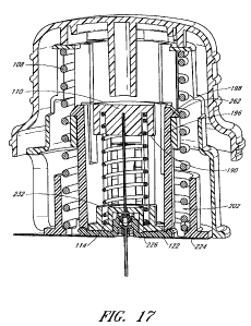
deliver medication.
10005J Subcutaneous injection ports are sometimes inserted into the skin using
an
insertion device.
SUMMARY OF THE DISCLOSURE
100061 Prior insertion devices do not adequately address the needs of users.
Some users may suffer from conditions, such as diabetic neuropathy. It can be
advantageous
for an insertion device for an infusion device to be easily grasped and
operated by diabetics
-1-
CA 02699875 2010-03-15
WO 2009/039013 PCT/US2008/075876
suffering from diabetic neuropathy. Diabetic neuropathy can cause numbness,
loss of
feeling and muscle weakness in the hands and fingers making fine motor control
difficult. At
times, a user may need to insert an infusion device at a location on the
user's body which
may complicate insertion, e.g., on a user's side or back. In some instances,
an adult may
need to assist a child in placing an infusion device on the child's body. In
these instances
and others, it can be beneficial for an insertion device for an infusion
device to require a
minimum number of operational steps while providing safe operation and
disposal. Such an
insertion device may advantageously minimize the possibility of accidental
needle sticks
and/or premature activation of the insertion device. Accordingly, it can be
advantageous for
an insertion device to insert an infusion device, such as an infusion set,
quickly, safely, and
conveniently.
[0007] Thus, in accordance with at least one of the embodiments disclosed
herein,
a device for inserting an infusion device through skin for subcutaneous
infusion comprises a
sleeve, a shuttle, at least a first biasing member, a hub, a needle, at least
a second biasing
member, and an actuator.
[0008] The sleeve can have an upper surface and a lower surface. The lower
surface of the sleeve can be configured to engage skin.
100091 The shuttle can comprise a receptacle for accommodating an infusion
device, at least a first inovement-restraining arm, and a least a first hub-
retaining arm. The
shuttle can be movable between a retracted position and an advanced position.
The first
movement-restraining arm can engage the upper surface of the sleeve when the
shuttle is in
the retracted position to inhibit movement of the shuttle toward the advanced
position. The
first biasing member can be operatively connected to the shuttle to urge the
shuttle toward
the advanced position.
100101 The hub can have an upper side and a lower side. The hub can be
movable between a first position and a second position with respect to the
shuttle. The first
hub-retaining arm of the shuttle can inhibit movement of the hub away from the
shuttle when
the hub is in the first position.
100111 The needle can have an upper end and a lower end. The upper end can be
fixedly attached to the lower side of the hub. The lower end can be configured
to pierce skin.
The lower end of the needle can extend below the lower surface of the sleeve
when the
-2-
CA 02699875 2010-03-15
WO 2009/039013 PCT/US2008/075876
shuttle is in the advanced position and the hub is in the first position. The
lower end of the
needle can be positioned above the lower surface of the sleeve when the hub is
in the second
position. The second biasing member can be operatively connected to the hub to
urge the
hub upwardly from the shuttle away from the lower surface of the sleeve.
[0012] The actuator can be movably attached to the sleeve such that, when the
first movement-restraining arm is engaged with the upper surface, advancement
of the
actuator toward the sleeve permits disengagement the first movement-
restraining arm of the
shuttle from the upper surface of the sleeve. Disengagement of the first
movement-
restraining arm of the shuttle from the upper surface of the sleeve can allow
the first biasing
3nember to move the shuttle from the retracted position to the advanced
position. Movement
of the shuttle from the retracted position to the advanced position can allow
the first hub-
retaining arm of the shuttle to release the hub such that the second biasing
member moves the
hub from the first position to the second position.
100131 In accordance with at least one of the embodiments disclosed herein, an
inserter for placing an infusion device at least partially into skin can
comprise a sleeve, a
carriage, at least at first biasing member, a hub, a needle, at least a second
biasing member,
and an actuator.
100141 The sleeve can have a bottom surface. The bottom surface can be
configured to engage skin.
[0015] The carriage can carry the infusion device. The carriage can be
positioned
at least partially within the sleeve. The carriage can be movable between a
retracted position
and an advanced position. The lowest portion of the infusion device can be
spaced upwardly
from the bottom surface of the sleeve when the carriage is in the retracted
position. The
bottom portion of the infusion device can extend below the lower surface of
the sleeve when
the carriage is in the advanced position. The first biasing member can be
operatively
connected to the carriage to urge the carriage toward the advanced position
[0016] The hub can be movable between a first position and a second position
with respect to the carriage. The needle can have an upper end and a lower
end. The upper
end can be fixedly attached to the lower side of the hub. The lower end can be
configured to
pierce skin. The needle can extend below the carriage when the hub is in the
first position.
The lower end of the needle can extend no lower than the carrrniage when the
hub is in the
-3-
CA 02699875 2010-03-15
WO 2009/039013 PCT/US2008/075876
second position. The second biasing member can be operatively connected to the
hub to urge
the hub upwardly from the carriage away from the lower surface of the sleeve.
[0017] The actuator can be operatively connected to the sleeve to cause the
first
biasing member to move the carriage from the retracted position to the
advanced position.
Movement of the carriage from the retracted position toward the advanced
position permits
the hub to move from the first position to the second position.
100181 In accordance with at least one of the embodiments disclosed herein, an
inserter for placing an infusion device at least partially into skin can
comprise a housing, I
carriage, at least at first biasing member, and an actuator.
100191 The housing can have a bottom surface_ The bottom surface can be
configured to engage skin.
100201 The carriage can be configured to carry an infusion device. The
carriage
can be positioned at least partially within the housing. The carriage can be
movable between
a retracted position and an advanced position. The lowest portion of the
infusion device can
be spaced upwardly from the bottom surface of the housing when the carriage is
in the
retracted position. The bottom portion of the infusion device can extend below
the lower
surface of the housing when the carriage is in the advanced position. The
carriage can
comprise at least one movable member for engaging the infusion device to
inhibit release of
the infusion device from the carriage before the carriage moves from the
retracted position
toward the advanced position. The first biasing member can be operatively
connected to the
carriage to urge the carriage toward the advanced position.
100211 The actuator can be operatively connected to the housing to cause the
first
biasing member to move the carriage from the retracted position to the
advanced position.
Moveinent of the carriage from the retracted position toward the advanced
position can cause
the hub to move from the first position to the second position.
10022] These and other embodiments of the present invention will become
readily
apparent to those skilled in the art from the following detailed description
of the preferred
embodiments having reference to the attached figures, the invention not being
limited to any
partieularpreferred embodiment(s) disclosed.
100231 Neither this summary nor the following detailed description purports to
define the invention. The invention is defined by the claims.
-4-
CA 02699875 2010-03-15
WO 2009/039013 PCT/US2008/075876
BRIEF DESCRIPTION OF THE DRAWINGS
100241 Specific embodiments will now be described with reference to the
drawings, which are intended to illustrate and not limit the various features
of the invention.
100251 Figure 1 is an exploded perspective view of an insertion device and an
insertion set according to one embodiment.
[0026] Figure 2 is an assembled perspective view of the insertion device of
Figure
100271 Figure 3 illustrates a protective cap removed from an actuator of the
insertion device of Figure 1.
[0028] Figure 4 is a side view of the actuator of the insertion device of
Figure 1.
100291 Figure 5 is a lower perspective view of the actuator of Figure 5.
100301 Figure 6 is an upper perspective view of the sleeve of the insertion
device
of Figure 1.
100311 Figure 7 is a lowerperspective view of the sleeve of Figure 6.
[0032] Figure 8 is a lower perspective view of a needle and needle hub of the
insertion device of F]gure 1.
100331 Figure 9 is an upper perspective view of a shuttle of the insertion
device of
Figure 1.
100341 Figure 10 is a cross-sectional view of the shuttle of Figure 9, taken
along
line 10-10 shown in Figure 9.
100351 Figure 11 is a cross-sectional view of the shuttle of Figures 9 and 10,
taken along line 11-11 shown in Figure 9.
[0036] Figure 12 is an upper perspective view of a protective cap for use with
an
insertion device.
100371 Figure 13 is an upper perspective view of the protective cap of Figure
12,
showing a portion of an infusion device accommodated therein.
100381 Figure 14 is a cross-sectional view of the insertion device of Figure l
before actuation, taken along line 14-14 shown in Figure 3.
[0039] Figure 15 is another cross-sectional view of the insertion device in
Figure
1 before actuation, taken along line 15-15 shown in Figure 14.
-5-
CA 02699875 2010-03-15
WO 2009/039013 PCT/US2008/075876
100401 Figure 16 is a cross-sectional view, similar to Figure 15, of the
insertion
device of Figure I after actuation.
[0041] Figure 17 is another cross-sectional view, similar to Figure 14, of the
insertion device of Figure 1 after actuation.
100421 Figure 18 is an exploded perspective view of an insertion device and an
insertion set according to one embodiment.
[0043] Figure 19 is an assembled perspective view of the insertion device of
Figure 18.
[0044] Figure 20 is a perspective view of an actuator of the insertion device
of
Figure 18.
100451 Figure 21 is a lower perspective view of the actuator of Figure 20.
100461 Figure 22 is an upper perspective view of a sleeve of the insertion
device
of Figure 18.
100471 Figure 23 is a lower perspective view of the sleeve of Figure 22.
[0048] Figure 24 is an upper perspective view of a needle hub of the insertion
device of Figure 18.
100491 Figure 25 is an upper perspective view of the shuttle of the insertion
device of Figure 18.
100501 Figure 26 is a lower perspective view of the shuttle of Figure 25.
[0051] Figure 27 is a cross-sectional view of the shuttle of Figures 25 and
26,
taken along line 27-27 shown in Figure 25.
[0052] Figure 28 is another cross-sectional view of the shuttle of Figures 25
and
26, taken along the line 28-28, shown in Figure 25.
100531 Figure 29 is a cross-sectional view, similar to Figure 27, of the
insertion
device of Figure 18 before actuation.
[00541 Figure 30 is a cross-sectional view, similar to Figures 27 and 29, of
the
insertion device of Figure 18 after actuation.
DETAILED DESCRIPTION OF SPECIFIC EMBODIMENTS
[0055] Figure I illustrates an embodiment of an insertion device 100 for an
infusion
device 102, such as infusion set. Further details regarding some exeinplifying
infusion
devices, including infusion sets, are provided in United States Patent
Application Publication
-6-
CA 02699875 2010-03-15
WO 2009/039013 PCT/US2008/075876
Nos. 2005/0107743 and 2007/0185441, both of which are hereby incorporated by
reference
herein in their entireties. There are many different types of infusion
devices, such as infusion
sets, that may be inserted using insertion devices, and the foregoing
publications are provided
merely to illustrate some infusion devices that can be used with or adapted to
be used with
the insertion devices described herein.
[00561 Referring to Figure 1, the insertion device 100 can comprise an
actuator 104, a
sleeve 106, an insertion spring 108, a needle hub 110, a needle 112, a
retraction spring 114, a
shuttle or carriage 116, a protective cap 1 l8, and a cover 120. The infusion
device 102 can
be an infusion set, and can comprise a base 122 and a tubing set 124. The base
122 can
comprise a soft cannula 264 and an adhesive sheet 266. The tubing set can
comprise an
infusion cap 240, a length of tubing 250, and a connector 254 (see Figure 13).
In same
embodiments, the infusion device 102 can be packaged within the insertion
device 100.
100571 Figure 2 illustrates the insertion device 100 in an assembled state
with the
protective cap 118 engaged witb the actuator 104. The protective cap 118 can
be removed
from the actuator 104, as shown in Figure 3, in preparation for insertion of
the base 122. In
some embodiments, the insertion device 100 may omit the cap 118.
100581 Referring to Figure 4, the actuator 104 can include one or more
gripping
surfaces 126, one or more pushing surfaces 130, one or more arms 134 having
feet 136, and a
coupling region 140. In some embodiments, the actuator 104 can be made of a
rigid plastic,
such as ABS (acrylonitrile butadiene styrene), polycarbonate, polyethylene, or
PET
(polyethylene terephthalate).
[00591 The gripping surface 126 can extend entirely or partially around the
circumference of the actuator 104 or may alternatively be located on opposite
sides of the
actuator 104 or otherwise spaced on the actuator 104. The gripping surface 126
preferably
has a dimension, such as an external diameter, that is sufficiently large to
facilitate easy
grasping by diabetics who have lost dexterity and strength due to diabetic
neuropathy. In
embodiments having multiple gripping surfaces 126, the gripping surfaces can
be spaced
apart by a distance for facilitate casy grasping. The gripping surface(s) 126
can also have
sufficient surface area and be positioned to allow a user to hold the actuator
104 at the
gripping surface(s) 126 using the middle section of a user's fingers and/or
palm.
-7-
CA 02699875 2010-03-15
WO 2009/039013 PCT/US2008/075876
100601 In some embodiments, the gripping surface 126 can include a plurality
of
ridges or other surface elements 128. Surface elements 128 can inerease
friction or interface
between a user's fingers and the actuator 104 to improve the user's ability to
securely hold
the actuator 104. For example, the surface elements 128 can comprise one or
more of
texturing, dimples, bumps, grooves, or other surface shapes. The surface
elements 128 can
be integrally formed with one or more other portions of the actuator 104, or
may be
separately formed and attached by mechanical coupling, such as by interference
fit, or by any
known bonding techniclue, such as adhesives.
100611 The pushing surfaces 130, 132 of the actuator 104 can comprise one or
more
upper pushing surfaces 130 and/or one or more lower pushing surfaces 132 that
can be sized
and positioned to be contacted by a user's fingers and/or palm. For example,
the upper
pushing surface 130 can be configured to be contacted primarily by a user's
palm, while
lower pushing surfaces 132 can be configured to be contacted primarily by a
user s fingers.
In the embodiment of the actuator 104 that is illustrated in Figure 4, the
upper pushing
surface 130 is generally convexly domed and the lower pushing surface 132 is
generally
concave.
100621 With continued reference to Figure 4, the actuator can comprise one or
more
arms 134 which can have feet 136. The feet 136 may be located at or near a
terminal end of
arms 134. The feet can include a cam surface 138 and may face outwardly, as
illustrated in
Figure 4, inwardly or circumferentially or in other directions. In some
embodiments, the
actuator 104 may omit the anns, feet, and cam surfaces. In some embodiments,
the actuator
104 can comprise other features.
100631 The coupling region 140 may facilitate secure attachment of the
actuator 104
with the protective cap 118 (see Figures 1 and 2). The coupling region 140 can
comprise a
groove 142 which can securely engage a complementary structure of the
protective cap 118,
while also allowing easy removal of the protective cap 118 from the actuator
104. In some
embodiments, the coupling region 140 can additionally or alternatively
comprise a ridge
which can securely engage a complementary strueture of the protective cap 118,
while also
allowing easy removal of the protective cap 118 from the actuator 104.
100641 Referring to Figure 5, the actuator 104 can comprise a number of
features in
an interior of the actuator 104. For example, the actuator 104 can comprise
one or more
-8-
CA 02699875 2010-03-15
WO 2009/039013 PCT/US2008/075876
displacement members 144, one or more guideposts 148, and a travel-limiting
member 152.
Some or all of the displacement members 144, the guideposts 148, and the
travel-limiting
member 152 can extend downwardly from the underside of the actuator 104. The
displacement member 144 can include an engagement surface 146. One or more of
the
guideposts 148 may include a stop surface 150. The travel-limiting member 152
may be
cylindrical, or may have other configurations, such as square, triangular,
frustoconical, or
actuate.
100651 Referring to Figure 6, the sleeve 106 can comprise an upper surface
154. The
upper surface 154 can include one or inore apertures 156 that are sized and
positioned to
cooperate with the guideposts 148 of the actuator 104. Alternatively, the
apertures 156 can
be formed in a surface of the sleeve other than the upper surface 154. In some
embodiments,
the apertures 156 can comprise recesses formed in the sleeve 106, such as in
the upper
surface 154, in a side surface, or both.
100661 The sleeve 106 can comprise one or more external guide rails 158 and/or
one
or more intemal guide rails 160. The external guide rails 158 are preferably
sized and
configured to cooperate with one or more interior surfaces of the actuator
104, such as
interior surface 260 (see Figure 5). For example, the external guide rails 158
can slidingly
engage the interior surface 260 of the actuator 104 to cause the actuator 104
and the sleeve
106 to move along a generally straight path with respect to one another. The
external guide
rails 158 can additionally or alternatively cooperate with one or more
interior surfaces of the
actuator 104 to allow the cap 104 and the sleeve 106 to rotate with respect to
each other. The
external guide rails 158 may extend generally linearly (e.g., straight), as
shown in Figure 6,
though the external guide rails 158 may also have other configurations.
100671 The internal guide rails 160 can be sized and configured to cooperate
with
appropriate structures of the shuttle 116, discussed below. The internal guide
rails 160 can
extend longitudinally, as shown on Figure 6, or may have other configurations.
In some
embodiments, the internal guide rails 160 are arranged in pairs to define a
channel
therebetween.
10068) With continued reference to Figure 6, the sleeve 106 can also comprise
a
recess 168. The recess 168 can permit one or more portions of the infusion
device 102 to
extend therethrough (see Figures 14 and 17).
-9-
. ~ CA 02699875 2010-03-15
WO 2009/039013 PCT/US2008/075876
100691 Referring again to Figure 6, the sleeve 106 can comprise one or more
apertures 166 that can be used to facilitate molding intemal features of the
sleeve 106.
10070] The sleeve 106 can also comprise a stop ledge 262, the purpose of which
is
described further below in connection with Figures 14-17.
100711 The sleeve 106 can comprise one or more apertures 162 that are
configured to
permit the arms 134 of the actuator 104 (see Figure 4) to extend therethrough.
The aperture
162 can have a width that allows the arm 134 to move within the aperture 162
as the actuator
104 is rotated with respect to sleeve 106 between a locked position and an
unlocked position.
When such embodiments are in the locked position, the stop surfaces 150 of the
actuator 104
can be positioned over the upper surface 154 of the sleeve 106 to prevent
movement of the
actuator 104 relative to the sleeve 106 toward the skin. When such embodiments
are in the
unlocked position, the stop surfaces 150 are aligned with the apertures 156
such that the
guideposts, including the stop surfaces, are allowed to advance through the
apertures 156.
The sleeve 106 can also comprise indicia 164 to indicate whether the actuator
104 and sleeve
106 are in the unlocked or locked position.
100721 Referring to Figure 7, the slceve 106 can comprise a recess 170 in
which the
one or more feet 136 of the actuator 134 may move. The recess 170 can be
bounded on one
side by a shoulder 172 that is configured to engage the one or more feet 136
of the actuator
104. The shoulder 172 can comprise a protrusion 174 to prevent unintentional
rotation of the
actuator 104 with respect to sleeve 106 between the locked position and the
unlocked
position. The protrusion 174 can also provide tactile fecdback to a user when
the actuator
104 is moved with respect to the sleeve 106 between the locked position and
the unlocked
position.
100731 The sleeve 106 can also comprise a lower surface 176. The lower surface
176
can be configured to provide stable contact with a person's skin during
placement of the base
122 of the infusion device 102 into the person's skin. The lower surface 176
can be
continuous, as illustrated in Figure 7, or segmented.
100741 In some embodiments, the sleeve 106 can comprise a recess 178 (see,
e.g.,
Figures 15 and 16) to receive all or a portion of the insertion spring 108
therein_
[0075] With continued reference to Figure 7, in some embodiments, the sleeve
106
can comprise a cam surface 180. The cam surface 180 can be cylindrical, as
illustrated in
-10-
CA 02699875 2010-03-15
WO 2009/039013 PCT/US2008/075876
Figure 7, or have other configurations. For example, the cam surface 180 can
have a
generally circular cross-section, as illustrated in Figure 7, or can have
other cross-sectional
shapes such as polygonal. The cam surface 180 can form a closed loop as shown
in Figure 7,
or may not form a closed loop, but instead comprise one or more longitudinal
cam surfaces.
[0076] In some embodiments, the sleeve 106 can be made of a rigid plastic,
such as
ABS, polycarbonate, polyethylene, or PET.
100771 Referring to Figure 8, the needle hub 110 can comprise an upper side
182 and
a lower side 184. The lower side 184 can comprise a needle-mounting aperture
186 and a
recess 188. The recess 188 can be configured to receive all or a portion of
the retraction
spring 114 (see Figures 1 and 14-17). The needle hub can also include one or
more
engagement surfaces 190 and a follower surface 192. In some embodiments, the
needle hub
110 can be made of a rigid plastic, such as ABS, polycarbonate, polyethylene,
or PET.
10078] The needle 112 can be inserted into and fixed within the needle-
mounting
aperture 186 of the needle hub 110. The needle 112 can be fixed to the needle
hub I10 by
any suitable adhesive, such as a solvent adhesive. The needle 112 can include
a beveled end
194. In some embodiments, the needle 112 can be made of a suitable metal, such
as stainless
steel.
100791 Referring to Figures 9-11, the shuttle 116 can include recesses 202
that are
configured to receive at least a portion of the insertion spring 108 (see
Figures 14-17). The
insertion spring 108 can engage the sleeve 106, and the insertion spring 108
can bias the
shuttle 116 from the sleeve 106. The guideposts 148 can extend through the
apertures 156 in
the sleeve 106 (Figure 6), and the insertion spring can engage the guideposts
148 to bias the
actuator from the shuttle 116 (see Figures 14 - 15).
100801 The shuttle 116 can include one or more sleeve-engaging arms 196, each
having a sleeve-engaging foot 198. The sleeve-engaging arms 196 of the shuttle
116 can be
biased so that the sleeve-engaging feet 198 rest upon the upper surface 154 of
the sleeve 106
to maintaining the insertion spring 108 in a compressed state (see Figure 14).
[0081] The sleeve-engaging feet 198 and upper surface 154 are preferably
configured
to align with the displacement member 144 of the actuator 144 so that the
engagement
surface 146 of the displacement member 144 aligns with cam surfaces 200 of the
sleeve-
engaging feet 198. Thus, movement of the displacement member 144 against the
feet 198
-11-
CA 02699875 2010-03-15
WO 2009/039013 PCT/US2008/075876
can cause the feet 198 to disengage from the upper surface 154 of the sleeve
106. The cam
surfaces 200 of the sleeve-engaging feet 198 can be beveled, as shown in
Figures 9-10 and
14, or alternatively the engagement surface 146 can be beveled.
100821 The shuttle 116 can be configured to accommodate the needle hub 110 and
needle 112. For example, the shuttle 116 can comprise one or more cam surfaces
204
configured to cooperate with the follower surface 192 of the needle hub 110 to
orient the
needle hub I 10 while permitting sliding movement of the needle hub I 10
relative to the
shuttle 116. The shuttle 116 can also comprise a needle aperture 206 to permit
the needle
110 to extend therethrough.
100831 Referring to Figure 11, the shuttle 116 can comprise one or more
recesses 208
to receive at least a portion of the retraction spring 114. The retraction
spring also can
engage the needle hub 110, at the recess 188 for example, and the retraction
spring 114 can
bias the needle hub 110 from the shuttle 116 (see Figures 14-17).
[00841 With continued reference to Figures 9-11, the shuttle 116 can include
one or
more needle-hub-engaging arms 210, each having a needle-hub-engaging foot 212.
The
needle-hub-engaging arms 210 can be biased away from the needle hub 110 to
allow the
needle hub 110 to move freely along the guide surfaces 204. The needle hub 110
can be
forced toward the shuttle 116 to compress the retraction spring 114 (see
Figures 14 and 15).
The needle-hub-engaging arms 210 can then be forced together so that the
needle-hub-
engaging feet 212 engage the upper side 182 of the needle hub 110 to restrict
movement of
the needle hub 110 away from the shuttle 116. The need] e-hub-engaging arms
210 can also
comprise a follower surface 214 (see Figure 11) that cooperates with the cam
surface 180 of
the sleeve 106 to prevent the needle-hub-engaging anns 210 from spreading
apart to release
the needle hub 210 (see Figures 15 and 16).
100851 Referring to Figure 9, the shuttle 116 can comprise guide surfaces 216
that are
sized in positioned to cooperate with the can surface 180 of the sleeve 106 to
orient of the
shuttlc 116 relative to the sleeve 106 as the shuttle 116 moves away from the
sleeve 106
under the force of the insertion spring 108.
100861 Referring to Figure 11, the shuttle 1] 6 can comprise slots 218 that
are sized
and configured to cooperate with internal guide rails 160 of the sleeve 106 to
inhibit or
-12-
CA 02699875 2010-03-15
WO 2009/039013 PCT/US2008/075876
prevent rotation of the shuttle 116 relative to the sleeve 106 and guide the
movement of the
sleeve-engaging arms 196 and sleeve-engaging feet 198.
100871 Referring to Figures 10 and 11, the shuttle 116 can comprise a recess
220 to
receive at least a portion of an infusion device 102. The recess 220 can be
positioned such
that the needle 112 extends through the needle apertures 206 and through the
cannula 264 of
the base 122. The shuttle 116 can also comprise additional surfaces such as
surfaces 222 and
224, to engage the infusion device 102.
100881 The shuttle 116 can comprise one or more base-retaining arms 226. In
some
embodiments, the base-retaining arms 226 can extend into the recess 220 to
engage the
infusion device 102. The arms 226 can include set-engagement surfaces 228 that
may
include features, such as ribs 230, to frictionally engage the base 122. The
set-engagement
surfaces 228 can be substantially flat or in other embodiments can be concave
or have other
shapes. The arms 226 can include surfaces 232 positioned for engagement by the
needle hub
110 to force the set-engagement surfaces 228 into contact with the infusion
device 102 to
prevent the infusion device 102 from unintentional disengagement from the
shuttle 116.
When the needle-hub-engaging arms 210 of the shuttle 116 hold the needle hub
110 to
maintain compression of the retraction spring 114, the engagement surface 190
of the needle
hub 110 can press against the engagement surfaces 232 to move the arms 226 and
thereby
squeeze the infusion device 102 between the set-engagement surfaces 228 within
the recess
220.
100891 In some embodiments, the shuttle 116 can be made of a rigid plastic,
such as
ABS, polycarbonate, polyethylene, or PET. Nonetheless, it can be advantageous
for the
material from which the shuttle 116 is made to have sufficient memory to
properly function
as described herein.
100901 Referring to Figures 12 and 13, the protective cap 118 can eomprise a
cylindrical wall 234 of sufficiently large width, diameter, or length, to
accoinmodate therein
the tubing set 124 as illustrated in Figure 13. The protective cap 118 can
include a plurality
of apertures 236 to facilitate the sterilization of the insertion device 100
and/or the infusion
device 102.
100911 The cover 120 (see Figures 1-3) can be applied to the protective cap
118 to
cover the apertures 236 before or after sterilization of the insertion device
100 and/or the
-13-
CA 02699875 2010-03-15
WO 2009/039013 PCT/US2008/075876
infusion device 102. In some embodiments, the cover 120 can be made of DuPont
Tyvek
or other suitable material.
10092J In some embodiments, the protective cap 118 can comprise one or more
stnactures to receive and retain the tubing set 124 of the infusion device
102. The protective
cap 118 can comprise one or more reeeiving structures 238 to receive the
infusion cap 240
and one or more arms 242 having feet 244 to hold the infusion cap 240 securely
within the
protective cap 118.
100931 The protective cap 118 can include a plurality of arms 246 having feet
248
that are configured to hold the length of tubing 250. One of the arms 246 can
also comprise a
recess 252 to receive the connector 254. The protective cap 118 can comprise a
recess 256 to
receive a portion of the connector 254 so that the connector 254 can be held
securely between
the recess 256 and the arm 246 that includes the recess 252.
100941 The protective cap I18 can comprise a coupling region 258 configured to
cooperate with the coupling region 140 of the actuator 104.
100951 In some embodiments, the protective cap 118 can be made of a rigid
plastic or
a semi-rigid plastic, such as ABS, polycarbonate, polyethvlene, or PET. In
some
embodiments, it may be desirable for the actuator 104 and the protective cap l
18 to be made
of different materials. For example, the protective cap 118 can be made of a
material that is
less rigid than the material of the actuator 104 to facilitate operation of
the coupling regions
120, 258. Additionally or alternatively, the protective cap 118 can be made of
a clear
material, such polycarbonate, to facilitate inspection of the infusion device
102 by a
manufacturer or user, for example.
100961 The protective cap 118 can advantageously be used for storage and
transportation of the tubing set 124. The protective cap 118 can also be used
as a sterile
environment for the infusion cap 240 while the connector 254 is connected to
an infusion
pump and the tubing set 124 is primed.
100971 The actuator 104, the sleeve 106, the shuttle 116, and the protective
cap 118
can be made of any of a variety of plastics known to those of skill in the
art, such as those
identified above, or may alternatively be made of metal or other materials.
The insertion
spring 108 and the retraction spring 114 can be made of plastic, metal,
rubber, or other
materials. In some embodiments the insertion spring 108 and the retraction
spring 114 can
-14-
CA 02699875 2010-03-15
WO 2009/039013 PCT/US2008/075876
be made of steel, such as stainless steel or spring steel. The springs 108 and
114 may have
configurations other than that of a helical spring.
10098] The insertion device 100 and infusion device 102 can be packaged
together
and transported in the assembled state shown in Figure 2. A label (not shown)
may be
applied to the side of the protective cap 118 and the actuator 104 to provide
instructions to
the user and provide a tamper-evident seal to the insertion device 100. The
label could be
positioned so that the user would need to tear the label before removing the
protective cap
118 from the actuator 104, as shown in Figure 3.
[0099] Once the protective cap 1 l8 is removed from the actuator 104, the
connector
254 and some or all of the length of tubing 250 are removed from the
protective cap 118.
The connector 254 is connected to an infusion pump and then the tubing set 124
is primed.
The infusion cap 240 is kept within the protective cap 118 to preserve the
sterility of the
infusion cap 240.
101001 After preparing an injection site on the patient's skin, the user
removes
protective paper backing, if any, from the adhesive of the base 122. The
sleeve 106 is then
rotated relative to the actuator 104 from the locked position to the unlocked
position and the
lower surface 176 of the sleeve 106 is placed on the skin at the injection
site.
101011 The actuator 104 can be advanced toward the skin with the extemal guide
rails
158, if present, of the sleeve 106 guiding the actuator 104 as it is advanced.
Advancement of
the actuator 104 toward the sleeve 106 can disengage or permit disengagement
the sleeve-
engaging feet 198 of the shuttle 116 from the upper surface 154 of the sleeve
106. For
example, referring to Figures 14 and 15, the actuator 104 compresses the
insertion spring 108
until the engagement surface 146 of the displacement member 144 of the
actuator 104
presses against the cam surfaces 200 of the sleeve-engaging feet 198 of the
shuttle 116 to
force the sleeve-engaging feet 198 off of the upper surface 154 of the sleeve
106 to allow the
shuttle 116 to advance within the sleeve 106. The orientation of the shuttle
116 within the
sleeve 106 can be preserved as the shuttle 116 advances by cooperation of the
intemal guide
rails 160 in cooperation with the slots 218 of the shuttle 116. Advancement of
the shuttle
116 within sleeve 106 can be limited by the engagement of the sleeve-engaging
feet 198
against the stop ledge 262 of the sleeve 106 (see Figure 17).
-15-
CA 02699875 2010-03-15
WO 2009/039013 PCT/US2008/075876
101021 Movement of the shuttle 116 from a retracted position toward an
advanced
position can permit or can cause the hub 110 to move away from the hub 110.
For example,
as the shuttle 160 approaches or arrives at the end of its range of travel
within the sleeve 106,
the needle-hub-engaging arms 210 can clear the cam surface 180 of the sleeve
106 to allow
the needle-hub-engaging arms 210 to move away from the needle hub 110. Once
the needle
hub 110 is released by the needle-hub-engaging arms 210, the retraction spring
114 can push
the needle hub 110 away from the shuttle 116 to draw the needle 112 within the
insertion
device 100, as illustrated in Figures 16 and 17. The guide surfaces 204 of the
shuttle 116 can
orient the needle hub 110 as it moves away from the shuttle 116 so that the
needle 1 l2 is
withdrawn substantially linearly (e.g., straightly) from the skin. Thus, the
needle 112 can be
protected both before and after insertion of the base 122 to prevent
accidental needle sticks.
This automatic retraction feature can ensure that the needle 212 is only
exposed while the
infusion device 102 is being inserted. In some embodiments, the insertion
device 100 can be
configured to be used only a single time such that the insertion device 100
can be discarded
with the needle safely retained therein.
10103J The surfaces 222 and 224 of the shuttle 116 can press the base 122
against the
skin. Additionally or alternatively, the surfaces 222 and 224 can inhibit
movement of the
infusion device 102 away from the skin as the needle 112 is retracted. In
embodiments
comprising arms 226 (see Figure 10), once the needle hub I 10 moves away from
the shuttle
116, pressure can be released from the engagement surface 232 of the arms 226
releasing the
set-engagement surfaces 228 from the base 122 so that the base 122 is released
froin the
shuttle 116.
[0104] The user may maintain pressure against the cap 104 so that the surfaces
222
and 224 of the shuttle 116 hold a portion of the infusion device 102, such as
the base 122,
against the skin to ensure good adhesion between the infusion device 102 and
the skin.
Thereafter, the user may lift the insertion device 100 away from the skin
leaving the infusion
device 102 against the skin with the cannula extending through the skin.
[01051 Once the insertion device 100 is removed from the skin, the protective
cap
118 can be engaged with the actuator 104 for safe disposal of the needle 112
within the
insertion device 100. However, in some embodiments, the insertion device 100
can be safely
-16-
CA 02699875 2010-03-15
WO 2009/039013 PCT/US2008/075876
disposed with the needle 112 retracted into the insertion device 100 even if
the protective cap
118 is omitted or not engaged with the actuator 104.
101061 In some embodiments, the insertion device 100 can be used to insert an
infusion set 102 having a rigid infusion cannula 264, such as those described
in United States
Patent Application Publication No. 2007/0185441, which is hereby incorporated
by reference
herein in its entirety. Such embodiments of the insertion device 100 may omit
the needle 112
if the infusion cannula 264 has sufficient rigidity to pierce skin.
101071 Figure 18 illustrates an embodiment of an insertion device 1100 for an
infusion device, such as the infusion device 102. The insertion device 1100 is
similar in
many respects to the insertion device 100. Therefore, similar components of
the insertion
device 1100 are referenced by the same reference numeral as the corresponding
component
in the insertion device 100 incremented by one thousand. As with the insertion
device 100,
the insertion device I 100 can comprise an actuator 1104, a sleeve 1106, an
insertion spring
1108, a needle hub 1110, a needle 1112, a retraction spring 1114, a shuttle
1116, a protective
cap 1118, and a cover 1120_ In some embodiments, the infusion device 102 can
be packaged
within the insertion device 1100.
[0108] The insertion device 1100 can differ from the insertion device 100 in
some
respects. For example, the actuator 1104 can comprise one or more projections
1107,
illustrated in Figures 19 and 20. The projections 1107 can extend generally
away from one
or more gripping surfaces 1126, one or more pushing surfaces 1130, or a
combination
thereof. The projections 1107 can be spaced substantially evenly around the
actuator 1104 or
can be otherwise spaced on the actuator 1104. The gripping surfaces 1126 can
extend
between the projections 1107.
[0109] The projections 1107 can provide one or more advantages. For example,
the
projections may aid in the removal of a protective wrapping, covering, or
other seal or
temper-evidencing feature. Insertion devices can be distributed to end-users
in a sealed
configuration to maintain the insertion devices in a sterile condition. In
some embodiments,
sterility can be maintained by distributing the insertion device 100, 1100 in
an assembled
state (Figures 3 and 19) and by substantially sealing the coupling region 140,
1140 between
the actuator 104, 1104 and the protective cap 118, 1118. In some embodiments,
the coupling
region 1140 can be wrapped with a layer of plastic or cellophane shrink-
wrapping, or a
-17-
CA 02699875 2010-03-15
WO 2009/039013 PCT/US2008/075876
shrink-wrapping formed from any other suitable material. While placing the
layer of shrink-
wrapping, covering, or other seal or temper-evidencing feature across the
coupling region
1140 may help to maintain sterility and can indicate whether tampering has
occurred, the
removal of such layer may be difficult for some users, particularly for those
suffering from
diabetic neuropathy because of the associated loss of dexterity. In some
embodiments, the
projections 1107 can comprise one or more surfaces 1105, as shown in Figure
19, to facilitate
removal of the shrink-wrapping, covering, or other seal or temper-evidencing
feature from
the coupling region 1140. For example, the shrink-wrapping could be removed by
rubbing
the surface 1105 against another object, creating a pressure on the shrink-
wrapping sufficient
to loosen, tear or otherwise remove the shrink wrapping. The surfaces 1105 may
also provide
a suitable location for provision of a tab, perforation, or other feature to
aid a user in
removing a protective wrapping, covering, or other seal or temper-evidencing
feature.
Additionally or alternatively, the projections 1107 may aid manipulation of
the actuator 1104
during use or manufacturing by indicating the orientation of the actuator
1104, providing
additional surfaces or surfaces for gripping, or both.
101101 As shown in Figure 20, the actuator 1104 can comprise one or more
apertures
1163. The actuator 1104 can comprise indicia 1165 to indicate whether the
actuator 1104
and the sleeve 1106 are in an unlocked position or a locked position.
101111 With reference to Figure 21, an interior of the actuator 1104 may
comprise
one or more displacement members 1144, one or more guideposts 1148, one or
more travel-
limiting members 1152, and one or more grooves or detents 1171. In some
embodiments, the
detents can have configurations other than that of grooves. In some
embodiments, such as
the embodiment illustrated in Figure 21, the grooves l 171 can be positioned
adjacent to the
one or more apertures 1163.
101121 Referring to Figures 22 and 23, the sleeve 1106 can comprise one or
more
arms 1135. Each arm 1135 can comprise a foot 1137. The feet 1137 can be
located at a
terminal end of the arms 1135. Each foot can include a cam surface 1139. The
feet 1137 can
face outwardly, as illustrated in Figures 22 and 23, inwardly,
circumferentialIy, or in other
directions.
10113] One or more of the arms 1135 can comprise a ridge 1175. The ridge 1175
can
be located centrally on an arm 1135 and can extend partially or entirely from
a base of the
-18-
CA 02699875 2010-03-15
WO 2009/039013 PCT[US2008/075876
arm to a terminal end, as shown in Figures 22 and 23. ln some embodiments, the
ridge 1175
can be located close to an edge of the arm 1135. While the ridges 1135
illustrated in Figures
22 and 23 are primarily straight with constant heights and widths along their
lengths, in other
embodiments the ridges can be curved or have a non-constant widths or heights.
In some
embodiments, the ridges can be circular and can resemble a single generally
circular bump or
a series of bump, or have other configurations.
101141 Referring again to Figure 20, the one or more apertures 1163 of the
actuator
1104 can be configured to permit a portion of one or more of the arms 1135,
the feet 1137,
the cam surfaces 1139, and the ridges 1175 of the sleeve 1106 (see Figures 22
and 23) to
partially or fully extend through the apertures 1163. The one or more
apertures 1163 can
have a width that allows a foot 1137 of the sleeve 1106 to move within the
aperture 1163 as
the actuator 1104 is rotated with respect to sleeve 1106 between the locked
position and the
unlocked position.
10115] The grooves 1171 can be configured to accept the ridge 1175 of the arm
1135
when the foot 1137 fully or partially extends through the aperture 1163.
Rotation of the foot
1137 along with the ann 1135 relative to the aperture 1163 is accompanied by
movement of
the ridge 1175 relative to the grooves 1171. In this manner, the locked
position can be
indicated by engagement of the ridge 1175 with one of the grooves 1171, and
the unlocked
position can be indicated by engagement of the ridge 1175 with the other of
grooves 1171.
Additionally or alternatively, the locked position can be indicated by
proximity of the foot
1137 to one of the indicia 1165 on the actuator 1104 as viewed through one of
the apertures
1163.
101161 In some embodiments, rotation of the arm 1135 relative to the aperture
1163
requires more force when the ridge 1175 is engaged with one of the grooves
1171. Thus,
unintentional rotation of the actuator 1104 with respect to the sleeve 1106
can be inhibited,
which unintentional rotation may accidentally unlock the device. Engagement of
the ridge
1175 and one of the grooves 1171 can also provide tactile feedback to the user
when the
actuator 1104 is moved between the locked position and the unlocked position.
[0117] ln other embodiments, the arm 1135 can comprise one or more grooves and
the actuator 1104 can comprise one or more ridges with the one or more grooves
and the one
or more ridges being configured to cooperate. Other configurations can also be
used. For
-19-
CA 02699875 2010-03-15
WO 2009/039013 PCT/US2008/075876
example, the arm 1135 can comprise one or more detents and the actuator 1104
can comprise
one or more bumps with the one or more detents and the one or more bumps being
configured to cooperate.
[01181 Figure 24 illustrates the needle hub I 110. In this embodiment, the
needle hub
1110 comprises an upper side 1182, a lower side 1184, a cylindrical follower
surface 1192,
and a protrusion 1183. The protrusion 1183 can be positioned on the upper side
1182, as
illustrated in Figure 24, or can in other embodiments be located on the lower
side 1184. The
protrusion 1183 may aid in assembling the insertion device 1100. For example,
it may
facilitate proper orientation of the needle hub 1110 during assembly of the
insertion device
1100. Additionally or alternatively, the protrusion 1183 may act as a handle
for manipulating
and stabilizing the needle hub during assembly.
101191 Figures 25-28 illustrate the shuttle 1116. The shuttle 1116 can
comprise one
or more recesses 1202 that are configured to receive at least a portion of the
insertion spring
1108. The shuttle 1116 can comprise one or more sleeve-engaging arms 1196 each
having a
sleeve-engaging foot 1198. The shuttle can comprise one or more cam surfaces
1204
configured to cooperate wiih the follower surface 1192 of the needle hub 1110
to orient the
needle hub 1110 while permitting sliding movement of the needle hub 1110
relative to the
shuttle 1116. The shuttle 1116 can comprise one or more recesses 1208 to
receive at least a
portion of the retraction spring 1114. The shuttle can comprise one or more
needle-hub-
engaging arms 1210, each having a needle-hub-engaging foot 1212.
101201 The shuttle 116 can coinprise a recess 1220 to receive at least a
portion of an
infusion device 102, such as an infusion set. The recess 1220 can be
positioned such that the
needle 1112 extends through the needle aperture 1206 and through the cannula
264 of the
base 122. The shuttle 1116 can also comprise additional surfaces such as sui-
faces 1222 and
1224, to engage the infusion device 102.
[01211 In some embodiments, the shuttle 1116 can comprise one or more base-
retaining arms 1226, such as those illustrated in Figures 25-28, to engage the
infusion device
102. In some embodiments, the base-retaining arms 1226 can be positioned in
base-retaining
arm recesses 1221. The arms 1226 can include base-retaining feet 1227, to
clamp, grasp, or
otherwise engage the base 122 and secure it to the shuttle 1116. The base-
retaining feet 1227
can be substantially flat or in other embodiments can be concave or have other
shapes. The
-20-
CA 02699875 2010-03-15
WO 2009/039013 PCT/US2008/075876
base-retaining anns 1226 can include sleeve-engagement surfaces 1233
positioned for
engagement by the cam surface 1180 of the sleeve 1106 to urge the base-
retaining feet 1227
toward the base 122 to impede unintentional disengagement of the infusion
device 102 from
the shuttle 1116. In some embodiments, the base-retaining feet 1227 can be
configured such
that when the cam surface 1180 is engaged with the sleeve-engagement surfaces
1233, the
base-retaining feet 1227 extend beneath a bottom edge of the base 122, thereby
physically
inhibiting separation of the infusion device 102 from the shuttle 1116.
101221 The insertion device 1 100 can be used as follows. Afler preparing an
injection site on the skin, the user can remove a protective paper backing, if
any, from an
adhesive of the base 122. The sleeve 1106 can then be rotated relative to the
actuator 1104
from the locked position to the unlocked position and a lower surface 1176 of
the sleeve
1106 can be placed on the skin at the injection site.
101231 The actuator 1104 can be advanced toward the skin, with the external
guide
rails 1158 of the sleeve 1106 guiding the actuator 1104 as it is advanced. The
actuator 1104
can compress the insertion spring 1108 until an engagement surface 1146 of the
displacement
member 1144 of the actuator 1104 presses against cam surfaces 1200 of the
sleeve-engaging
feet 1198 of the shuttle 1116 to force the sleeve-engaging feet 1198 off of an
upper surface
1154 of the sleeve 1106 to allow the shuttle 1116 to advance within the sleeve
1106. The
orientation of the shuttle 1116 within the sleeve 1106 can be preserved as the
shuttle 1116
advances by cooperation of internal guide rails 1160 in cooperation with slots
1218 of the
shuttle 1116. Advancement of the shuttle 1116 within sleeve 1106 can be
limited by the
engagement of the sleeve-engaging feet 1198 against one or more stop ledges
1262 of the
sleeve 1106 (see Figure 30).
101241 As the shuttle 1116 advances through the sleeve 1106, the sleeve-
engagement
surfaces 1233 of the shuttle 1116 can advance downwardly relative to the cam
surface 1180
of the sleeve 1106. The base-retaining arms 1226 can spread outwardly when the
sleeve-
engagement surfaces 1233 of the shuttle 1116 clear the cain surface 1180 of
the sleeve 1106.
The base-retaining feet 1227 can move away from the base 122 as the base-
retaining arms
1126 spread outwardly such that the base 122 can be released from the shuttle
1116.
101251 As the shuttle 1116 approaches or arrives at the end of its range of
travel
within the sleeve 1106, the needle-hub-engaging arms 1210 can clear the cam
surface 1180
-21-
CA 02699875 2010-03-15
WO 2009/039013 PCT/US2008/075876
of the sleeve 1106 to allow the needle-hub-engaging ar,ms 1210 to move away
from the
needle hub 1110. Once the needle hub l 110 is released by the needle-hub-
engaging arms
1210, the retraction spring 1114 can push the needle hub l 110 away from the
shuttle 1116 to
draw the needle 1112 within the insertion device l 100. The guide surfaces
1204 of the
shuttle 1116 can orient the needle hub I 110 as it moves away from the shuttle
1116 so that
the needle 1112 can be withdrawn substantially linearly (e.g., straightly)
from the patient's
skin. Thus, the needle 1112 can be protected both before and after insertion
of the base 122
to prevent accidental needle sticks. This automatic retraction feature can
ensure that the
needle 1212 is only exposed while the infusion device 102 is being inserted.
101261 Surfaces 1222 or 1224 of the shuttle 1116, or both, can press the base
122
against the skin. The user may maintain pressure against the cap 104 so that
the surfaces
1222 and 1224 of the shuttle l l 16 can hold the base 122 against the skin to
ensure good
adhesion between the base 122 and the skin. Thereafter, the user may lift the
insertion device
1100 away from the skin leaving the base 122 against the skin with the cannula
extending
through the skin.
101271 Once the insertion device 1100 is removed from the skin, the protective
cap
1118 can be engaged with the actuator 1104 for safe disposal of the needle l
112 within the
insertion device 1100.
101281 In some embodiments, the insertion device 1100 can be used to insert an
infusion device 102, such as an infusion set, having a rigid infusion cannula
264, such as
those described in United States Patent Application Publication No.
2007/0185441, whicb is
hereby incorporated by reference herein in its entirety. Such embodiments of
the insertion
device 1100 may omit the needle 1 l 12 if the infusion cannula 264 has
sufficient rigidity to
pierce the skin. Additionally, in embodiments of the insertion device 1100
wherein
movement of the needle hub 1110 within the insertion device 1100 does not
affect
securement of the base 122 of the infusion device 102 to the shuttle 1116, the
needle hub
1110 and the retraction spring 1114 may be omitted. If these components are
omitted,
corresponding simplifications to the structure of the shuttle 1116 may also be
made. Other
components, structures, or processes can be omitted in these and other
embodiments.
101291 The examples shown in the drawings of this application and described in
the
text are not intended to be limiting, but merely to illustrate various aspects
of certain
-22-
CA 02699875 2010-03-15
WO 2009/039013 PCT/US2008/075876
embodiments. Many other alternatives and configurations are possible, and are
encompassed
by this disclosure. Moreover, each of the components and features described
herein with
respect to each embodiment can be used in other embodiments of this disclosure
to form
additional embodiments not expressly illustrated or described. In addition, no
component,
structure, or process disclosed herein is indispensible or critical.
-23-