Note: Descriptions are shown in the official language in which they were submitted.
CA 02700102 2010-04-14
EXTENDABLE/RETRACTABLE STUDS FOR A TIRE
Field of the Invention
[001] The present invention relates generally to studs for a tire and, more
particularly, to retractable studs for a winter tire.
Background of the Invention
[002] Since the advent of the powered wheel, man has searched for means to
enhance the traction of the wheel with the surface upon which it operates.
Early on, the
wide steel driving wheels of steam powered traction machinery were equipped
with
massive steel lugs, which bit into the earth and gave the wheel the traction
required to
pull a number of breaking or turning plows through the earth. The wide wheels
were
necessary to provide the area required and support the tractor against sinking
into the
earth. The lugs provided the grip in the soil required to pull the plows.
[003] The coming of the horseless carriage created an entirely new set of
problems, as it was nothing more than a motorized adaptation of a horse-drawn
vehicle,
having free-turning wheels, which were meant to be pulled across the earth,
rather than
propelled by the powered rotation of the wheels. It was soon discovered that
the steel
band, or tire, that encircled the wooden wheel rims, was only suitable for use
on hard-
packed and dry surfaces. From this discovery, there evolved the wider solid
rubber and
subsequently the pneumatic tire.
[004] Since the evolution of the pneumatic tire, great effort has been
dedicated
in the search for means to improve the traction of the driving wheels of all
manner of
CA 02700102 2010-04-14
vehicles upon the surface and under the conditions which they must operate.
Water, mud,
and snow are three of the most difficult conditions to address with a modern
vehicle tire.
Each of these conditions requires a specific tire tread suited either to
"channelize" the
water away from the tire or grip the soft or slippery surface and either bring
more
material under the tread area or compact the material to provide a suitably
stable driving
surface. These conditions however, pale by comparison with the problems
encountered
when operating a wheeled vehicle on an ice covered surface.
[0051 No amount of tread, ribs, bars, and/or other such means are effective
upon
a surface of solid ice. While time-honored detachable tire chains or cleats
provide a
measure of traction under these conditions, their use has never been popular
due to the
difficulty of installation/removal and the bone-shaking ride which they impart
to a
vehicle employing them.
[006] In an attempt to solve these problems, the conventional "studded tire,"
which comprises a tread area which includes a number of hard stud-like
projections
which extend a short distance beyond the face of the tread to slightly
penetrate the
surface of the ice and thereby provide a limited mount of traction between
tire and iced
roadway, was developed. While it appeared that the studded tire would be the
definitive
solution to the operation of a vehicle on an ice covered surface, such was not
the case.
Soon after the introduction of studded tires, street and highway officials
began to detect
rapid deterioration of street and roadway surfaces and called for legislation
to restrict or
ban their use. Today, in most states and municipalities, the use of the
studded tire is
controlled by law, ordinance, or regulation requiring that such tires be used
only during
certain winter months and that such tires be removed from service during the
warmer
2
CA 02700102 2010-04-14
months. Further, some states have enacted legislation which prohibits the use
of such
tires at any time and have thus deprived motorists of the safety and
convenience
advantages of such tires.
[0071 Another factor which has to some extent lessened the popularity of the
studded tire is the fact that the protruding stud reduces, to a certain
degree, the ability of
the tire to grip a dry roadway with a consequent diminution of braking action.
Also, the
rotation of the studded tire upon a dry roadway causes an undesirable noise
and vibration
inside the vehicle. Further, the requirement for removal of studded tires
during the
warmer months and their re-installation for the winter requires either a
second set of
wheels for each vehicle or the semi-annual removal and replacement of the
tires upon the
same wheels with the consequent potential for damage to the "bead" or air
sealing area of
the tire. Of lesser importance, but still a factor affecting their popularity,
is the
requirement for storage space for the second set of tires when they are out-of-
service.
[0081 In the more temperate areas of the nation, the requirement for ice studs
is
virtually non-existent or may be limited to only a few days a year and quite
possibly only
for a portion of those days. For example, in the United States, regions south
of the 31st
parallel, except in the higher elevations, are seldom subject to climatic
conditions which
produce freezing rain and the consequent coating of ice which makes studded
tires
desirable. Conversely, the area north of the 36 degree, 30 foot parallel is
likely to have
ice, snow, or a combination of both on the ground for many days or even weeks
of the
year. The area between these two parallels may have an ice storm overnight
which may
result in almost impossible driving conditions during a morning commute, while
the
evening commute may be made on dry, or nearly dry, roadways.
3
CA 02700102 2010-04-14
[009] In order to accommodate the differing requirements of various quickly
changing geographical and climatic regions, one conventional tire provides a
plurality of
retractable traction enhancing elements. This conventional tire has two
substantially
concentric casings which are selectably inflatable or deflatable to cause the
extension or
retraction of stud-like anti-skid projections.
[010] Another conventional tire has stud-like projections which may be forced
through the tread area of the tire by differential air pressure between the
interior of the
casing and hoses which pass about the inner periphery of the casing and pass
under stud-
like projections. Still another conventional tire employs a similar
differential air pressure
system for extending and retracting studs through the tread area of the tire
and further
provides an internal reservoir for high pressure actuating air within the
casing and a
specialized valve for filling the reservoir and extending or retracting the
studs.
[011] Yet another conventional tire employs a multi-chambered casing which
allows the pneumatic outward flexure of a centrally situated stud-bearing band
about the
periphery of the tire at the center of the tread band into a road contacting
position. Still
another conventional tire provides "tire pressure dependent" traction
enhancing studs for
use on ice covered roadways. This conventional tire has an operator or driver
selectable
"on-demand" feature for engaging and disengaging traction enhancing studs.
[012] While these conventional tires may be functional, none have provided
wide-spread availability due to manufacturing and cost constraints. Thus,
these
conventional tires have not been adopted by the tire industry and have thus
been relegated
to obscurity. A tire that may be employed year-round without causing
unnecessary wear
4
CA 02700102 2010-04-14
to the roadway, yet be instantly available in a studded configuration when
required,
would be desirable.
Summary of Invention
[0131 A tire in accordance with the present invention includes a carcass, a
tread
band having a radially outer tread surface and a plurality of radially
extending recesses,
and an anti-slip structure disposed in one of the radially extending recesses.
The
structure includes a cylindrical housing with a cylindrical flange and a
central channel
and a stud portion with a shaft and a flange. The shaft is slidingly disposed
within the
central channel such that a radially outer tip of the shaft may selectably
extend radially
outward from the cylindrical housing and from the radially outer tread surface
in order to
enhance traction for the tire. The radially outer tip extends from the
cylindrical housing
and from the radially outer tread surface when a predetermined air pressure is
introduced
into the radially extending recess thereby forcing the flange of the stud
portion radially
outward to abut the cylindrical flange of the cylindrical housing.
10141 In accordance with another aspect of the present invention, the
cylindrical
housing of the structure further includes a radially inner surface, an
opposite radially
outer surface, and a biasing element extending radially inward from the
radially inner
surface. The biasing element maintains the radially outer tip of the stud
portion in an
unextended position when air pressure in the radially extending recess is less
than the
predetermined air pressure.
CA 02700102 2010-04-14
[015] In accordance with still another aspect of the present invention, the
predetermined air pressure is introduced into the radially extending recess by
an axially
extending channel.
[016] In accordance with yet another aspect of the present invention, the
axially
extending channel interconnects a radially innermost portion of the radially
extending
recess and an axially outer side portion of the tread band.
[017] In accordance with still another aspect of the present invention, the
cylindrical housing of the structure further includes a radially inner
surface, an opposite
radially outer surface, and a biasing element extending radially inward from
the radially
inner surface. The biasing element compresses into a recess at the radially
inner surface
when the predetermined air pressure is present in the radially extending
recess.
[018] In accordance with yet another aspect of the present invention, the tire
is a
pneumatic tire and the predetermined air pressure is supplied by an inflation
pressure of
the pneumatic tire.
[019] In accordance with still another aspect of the present invention, the
radially outer tip of the stud portion is flush with an outer surface of the
cylindrical
housing and the radially outer tread surface when air pressure in the radially
extending
recess is less than the predetermined air pressure.
[020] In accordance with yet another aspect of the present invention, the
plurality of radially extending recesses each have a shoulder portion for
limiting radially
outer movement of the flange of the housing.
6
CA 02700102 2010-04-14
[021] In accordance with still another aspect of the present invention, the
flange
of the housing limits radially outer movement of the flange of the stud
portion.
[022] In accordance with yet another aspect of the present invention, a
sealing
element seals the predetermined air pressure within the radially extending
recess.
Definitions
[023] The following definitions are controlling for the disclosed invention.
[024] "Apex" refers to a wedge of rubber placed between the carcass and the
carcass turnup in the bead area of the tire, usually used to stiffen the lower
sidewall of the
tire.
[025] "Aspect ratio" of the tire means the ratio of its section height (SH) to
its
section width (SW) multiplied by 100% for expression as a percentage.
[026] "Annular" means formed like a ring.
[027] "Axial" and "axially" mean lines or directions that are parallel to the
axis
of rotation of the tire; synonymous with "lateral" and "laterally".
[028] "Bead" means that part of the tire comprising an annular tensile member
wrapped by ply cords and shaped, with or without other reinforcement elements
such as
flippers, chippers, apexes, toe guards and chafers, to fit the design rim.
[029] "Belt reinforcing structure" means at least two layers of plies of
parallel
cords, woven or unwoven, underlying the tread, unanchored to the bead, and
having both
7
CA 02700102 2010-04-14
left and right cord angles in the range from 17 degrees to 27 degrees with
respect to the
equatorial plane of the tire.
[030] "Belt structure" means at least two annular layers or plies of parallel
cords, woven or unwoven, underlying the tread, unanchored to the bead, and
having both
left and right cord angles in the range from 17 degrees to 27 degrees with
respect to the
equatorial plane of the tire.
[031] "Bias ply tire" means a tire having a carcass with reinforcing cords in
the
carcass ply extending diagonally across the tire from bead core to bead core
at about a 25
degree to 50 degree angle with respect to the equatorial plane (EP) of the
tire. Cords run
at opposite angles in alternate layers.
[032] "Breakers" refers to at least two annular layers or plies of parallel
reinforcement cords having the same angle with reference to the equatorial
plane of the
tire as the parallel reinforcing cords in carcass plies.
[033] "Buffed" means a procedure whereby the surface of an elastomeric tread
or casing is roughened. The roughening removes oxidized material and permits
better
bonding.
[034] "Building Drum" refers to a cylindrical apparatus on which tire
components are placed in the building of a tire. The "Building Drum" may
include
apparatus for pushing beads onto the drum, turning up the carcass ply ends
over the
beads, and for expanding the drum for shaping the tire components into a
toroidal shape.
8
CA 02700102 2010-04-14
[035] "Carcass" means the tire structure apart from the belt structure, tread,
undertread, and sidewall rubber over the plies, but including the beads.
[036] "Casing" means the carcass, belt structure, beads, sidewalls, and all
other
components of the tire including a layer of unvulcanized rubber to facilitate
the assembly
of the tread, the tread and undertread being excluded. The casing may be new,
unvulcanized rubber or previously vulcanized rubber to be fitted with a new
tread.
[037] "Center plane" means the plane perpendicular to the axis of rotation of
the
tread and passing through the axial center of the tread.
[038] "Circumferential" means lines or directions extending along the
perimeter
of the surface of the annular tire parallel to the equatorial plane (EP) and
perpendicular to
the axial direction.
[039] "Chafers" refers to narrow strips of material placed around the outside
of
the bead to protect cord plies from the rim, distribute flexing above the rim,
and to seal
the tire.
[040] "Chippers" mean a reinforcement structure located in the bead portion of
the tire.
[041] "Cord" means one of the reinforcement strands of which the plies in the
tire are comprised.
[042] "Design rim" means a rim having a specified configuration and width.
For the purposes of this specification, the design rim and design rim width
are as
9
CA 02700102 2010-04-14
specified by the industry standards in effect in the location in which the
tire is made. For
example, in the United States, the design rims are as specified by the Tire
and Rim
Association. In Europe, the rims are as specified in the European Tyre and Rim
Technical Organisation - Standards Manual and the term design rim means the
same as
the standard measurement rims. In Japan, the standard organization is The
Japan
Automobile Tire Manufacturer's Association.
[0431 "Design rim width" is the specific commercially available rim width
assigned to each tire size and typically is between 75% and 90% of the
specific tire's
section width.
10441 "Equatorial plane (EP)" means the plane perpendicular to the tire's axis
of
rotation and passing through the center of its tread.
[0451 "Filament" refers to a single yarn.
[0461 "Flipper" refers to reinforcing fabric around the bead wire for strength
and
to tie the bead wire into the tire body.
[0471 "Footprint" means the contact patch or area of contact of the tire tread
with a flat surface at zero speed and under normal load and pressure.
[0481 "Groove" means an elongated void area in a tread that may extend
circumferentially or laterally about the tread in a straight, curved, or
zigzag manner.
Circumferentially and laterally extending grooves sometimes have common
portions.
The "groove width" is equal to tread surface occupied by a groove or groove
portion, the
width of which is in question, divided by the length of such groove or groove
portion;
CA 02700102 2010-04-14
thus, the groove width is its average width over its length. Grooves may be of
varying
depths in a tire. The depth of a groove may vary around the circumference of
the tread,
or the depth of one groove may be constant but vary from the depth of another
groove in
the tire. If such narrow or wide grooves are of substantially reduced depth as
compared
to wide circumferential grooves which they interconnect, they are regarded as
forming
"tie bars" tending to maintain a rib-like character in the tread region
involved.
[049] "Inboard side" means the side of the tire nearest the vehicle when the
tire
is mounted on a wheel and the wheel is mounted on the vehicle.
[050] "Inner" means toward the inside of the tire and "outer" means toward its
exterior.
[051] "Lateral" means an axial direction.
[052] "Lateral edge" means the axially outermost edge of the tread as defined
by
a plane parallel to the equatorial plane and intersecting the outer ends of
the axially
outermost traction lugs at the radial height of the inner tread surface.
[053] "Leading" refers to a portion or part of the tread that contacts the
ground
first, with respect to a series of such parts or portions, during rotation of
the tire in the
direction of travel.
[054] "Net contact area" means the total area of ground contacting tread
elements between the lateral edges around the entire circumference of the
tread divided
by the gross area of the entire tread between the lateral edges.
11
CA 02700102 2010-04-14
[055] "Net-to-gross ratio" means the ratio of the tire tread rubber that makes
contact with a hard flat surface while in the footprint, divided by the area
of the tread in
the footprint, including non-contacting portions such as grooves.
[056] "Nominal rim diameter" means the average diameter of the rim flange at
the location where the bead portion of the tire seats.
[057] "Normal inflation pressure" refers to the specific design inflation
pressure
and load assigned by the appropriate standards organization for the service
condition for
the tire.
[058] "Normal load" refers to the specific design inflation pressure and load
assigned by the appropriate standards organization for the service condition
for the tire.
[059] "Outboard side" means the side of the tire farthest away from the
vehicle
when the tire is mounted on a wheel and the wheel is mounted on the vehicle.
[060] "Pantographing" refers to the shifting of the angles of cord
reinforcement
in a tire when the diameter of the tire changes, e.g. during the expansion of
the tire in the
mold.
[061] "Ply" means a continuous layer of rubber-coated parallel cords.
[062] "Pneumatic tire" means a laminated mechanical device of generally
toroidal shape (usually an open torus) having beads and a tread and made of
rubber,
chemicals, fabric and steel or other materials. When mounted on the wheel of a
motor
12
CA 02700102 2010-04-14
vehicle, the tire through its tread provides traction and contains the fluid
or gaseous
matter, usually air, that sustains the vehicle load.
[063] "Radial" and "radially" mean directions radially toward or away from the
axis of rotation of the tire.
[064] "Section height" means the radial distance from the nominal rim diameter
to the outer diameter of the tire at its equatorial plane.
[065] "Shoulder" means the upper portion of sidewall just below the tread
edge.
Tread shoulder or shoulder rib means that portion of the tread near the
shoulder.
[066] "Tread Width" means the arc length of the tread surface in the axial
direction, that is, in a plane parallel to the axis of rotation of the tire.
[067] "Undertread" refers to a layer of rubber placed between a reinforcement
package and the tread rubber in a tire.
[068] "Unit tread pressure" means the radial load borne per unit area (square
centimeter or square inch) of the tread surface when that area is in the
footprint of the
normally inflated and normally loaded tire.
[069] "Wedge" refers to a tapered rubber insert, usually used to minimize
curvature of a reinforcing component, e.g. at a belt edge.
[070] "Wings" means the radial inward extension of the tread located at axial
extremes of the tread, the inner surface of the wing being an extension of the
inner casing
contacting surface of the tread.
13
CA 02700102 2010-04-14
10711 "Year-round" means a full calendar year through each season. For
example, a snow tire is not designed for year-round use since it creates
objectionable
noise on dry road surfaces and is designed to be removed when the danger of
snow is
passed.
Brief Description of the Drawings
[0721 The invention will be described by way of example and with reference to
the accompanying drawings in which:
FIG. 1 is a schematic perspective view of a tire for use with a structure in
accordance with the present invention.
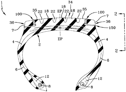
FIG. 2 is a schematic sectional view of the tire of FIG. 1.
FIG. 3 is a schematic detail view of part of the tire of FIG. I with the
structure
under a first condition.
FIG. 4 is a schematic detail view of part of the tire of FIG. 1 with the
structure
under a second condition.
FIG. 5 is a schematic exploded view of the structure of FIGS. 3 and 4.
Detailed Description of an Example Embodiment of the Present Invention
[0731 FIG. 1 shows a cross-section of an example tire 1 for use with the
present
invention. The tire 1 comprises a torus-shaped carcass 2, of the radial or of
the cross-ply
type, comprising a resistant structure which is formed by at least a
rubberized fabric ply 4
reinforced with textile or metal cords and having turnup ends 6 each fixed to
a pair of
14
CA 02700102 2010-04-14
circumferentially unextendable, preferably metallic, annular core, known and
referred to
hereinbelow as reinforcing bead cores 8. The bead cores 8 are provided with
rubber
filling apexes 12. The zone of the example tire 1 comprising the bead core 8
and filling
apex 12 forms the bead, intended for fixing the tire 1 to a corresponding
mounting rim
(not shown).
[074] The carcass 2 has arranged on it, in a known manner, a tread band 34
which is intended for the rolling contact of the example tirel on the ground
and is
provided with a raised pattern comprising grooves 22 formed in the thickness
of the tread
band 34 and define a plurality of blocks and/or ribs 18. The combination of
these
structural elements, in various configurations, produces different tread
patterns which are
generally optimized for different applications of the example tire 1.
[075] Together with the carcass 2 of the example tire 1, a belt structure 26
is
arranged on the crown of carcass, in between the carcass ply 4 and the tread
band 34,
axially extending from one side to the other of the example tire, i.e. as wide
as the tread
band 34. The belt structure 26 may include at least two rubberized fabric
strips 28, 30,
radially superimposed with textile and/or metallic reinforcing cords parallel
to one
another in each strip, mutually intersecting with those of the adjacent strip
and with
respect to the equatorial plane EP of the example tire. The belt structure 26
may also
include a radially outermost strip 32 with textile and/or metallic reinforcing
cords,
oriented at 0 degrees relative to a circumferential direction of the example
tire 1.
[076] The thickness of the tread band 34 may be between 8 mm and 24 mm, and
more specifically, between 15 mm and 16 mm for passenger tires, between 8 mm
and 11
CA 02700102 2010-04-14
mm for light truck tires, and between 18 mm and 24 mm for medium truck tires.
The
tread band 34 may be constructed of a compound generally suitable for winter
usage, and
specifically suited for winter usage with studs. The tread band 34 may have,
inserted in
it, a plurality of structures 100 in accordance with the present invention.
[077] The structures 100 may provide anti-slip elements for enhanced snow and
ice
traction. The structures 100 may be received in recesses 3 that secure the
structures
within the tread band 34. An air channel 5 extends axially from the radially
innermost
portion of the recess 3 to the outer surface 7 of the lateral side 36 of the
tread band 34.
[078] Each structure 100 includes a housing 110, stud portion 130 slidingly
secured
within the housing, and a sealing element 150 for maintaining air pressure
within the air
channel 5. The housing 110 has a cylindrical configuration with a central
channel 112 for
receiving part of the stud portion 130, a cylindrical flange 114 for securing
the housing
against radially outward movement, and a spring biasing element 116 for
biasing part of
the stud portion radially inward. The spring biasing element 116 may be
constructed of
any suitable resilient material, such as rubber or a thermoplastic, such that
the stud
portion 130 remains in a retracted position and resists the centripetal forces
generated
upon rotation of the tire 1.
[079] When installed in the tire 1, the housing 110 of each structure 100 is
disposed within each recess 3 of the tire 1 with the radially outer surface
118 of the
cylindrical flange 114 abutting a shoulder portion 7 of the recess (Figs. 3 &
4). Also,
when installed, a shaft 132 of the stud portion 130 is slidingly disposed
within the central
channel 112 of the housing 110 and the shaft extends radially inward to a
flange 134 of
16
CA 02700102 2010-04-14
the stud portion 130 located at the intersection of the radially innermost
portion of the
recess 3 and the axially innermost portion of the air channel 5. The diameter
of the recess
3 may be larger than the diameter of the shaft 132 so that the shaft may still
slide with t
he recess when the tread band 34 compresses under the load of a vehicle.
[080] The housing 110 may be constructed of an elastic material similar to the
material of the tread band 34 (i.e., a rubber composition) so as to wear as
the radially
outer surface 35 of the tread band wears. A radially outer surface 119 of the
housing 110
may thereby be continually flush with the outer surface 35 of the tread band
34. The stud
portion 130 may be constructed of an elastic material suitably hard to
grip/penetrate ice,
but suitably soft such that a tip 136 of the shaft 132 wears as the radially
outer surface 35
of the tread band 34 wears thereby reducing noise, improving handling and
comfort,
extending functional life of the tire, avoiding road damage (such as damage
caused by
conventional steel studs). The tip 136 of the shaft 132 may thereby be
continually flush
with the outer surface 35 of the tread band 34 and the outer surface 119 of
the housing
110 when the shaft is in an unextended position (Fig. 3), as described below.
The spring
biasing element 116 may or may not be constructed of the same material as the
housing
110. The housing 110 may alternatively be constructed of an inelastic material
with
suitable strength and wear properties.
[081] The spring biasing element 116 may or may not be integral to the housing
110. The spring biasing element 116 may or may not be a complete cylinder
circumscribing the shaft 132 of the stud portion 130 or a cylindrical array of
projections
extending from a radially inner surface 120 of the housing 110. The housing
110 may
17
CA 02700102 2010-04-14
have a recess 121 disposed at the radially inner surface 120 of the housing
110 for
accommodating the spring biasing element 116 in a compressed position (Fig.
4).
[0821 During normal, non-winter, non-icy conditions, when ice traction is
unneeded, the shaft 132 of the stud portion 130 may be in an unextended
position (Fig. 3)
with the tip 136 of the shaft 132 flush with the radially outer surface 119 of
the housing
110 and the radially outer surface 35 of the tread band 34. When ice traction
is needed, a
predetermined air pressure (i.e., 29 psi) may be introduced in a suitable
manner into the
air channel 5. The predetermined air pressure acts on the underside of the
flange 134 of
the stud portion 130, thereby moving the upper side of the flange radially
outward against
the spring biasing element 116 of the housing 110. The spring biasing element
116
compresses and allows the flange 134, and thereby the tip 136 of the shaft
132, to move
radially outward relative to the housing 110 and the tread band 34. The tip
136 of the
shaft 132 may thus extend radially outward beyond the radially outer surface
35 of the
tread band 34 and may provide ice traction in a manner similar to conventional
studs.
The usage of the tip 136 of the structure 100 is thereby occasional, not
continual.
[0831 When ice traction is no longer needed, the predetermined air pressure
may
be released from the air channel 5. The spring biasing element 116 may thereby
move
the flange 134 radially inward and retract the tip 136 of the shaft 132 until
ice traction is
once more needed. A plug 150 for sealing the air channel 5 is shown at the
axially outer
portion of the air channel (Fig. 4), but any suitable mechanism may be
utilized to
selectively seal the predetermined air pressure within the air channel.
18
CA 02700102 2010-04-14
[084] One example structure 100 may have a flange 114 of a housing 110 with a
diameter of 10.0 mm and a shaft 132 of a stud portion 130 with a diameter of
1.2 mm.
The source of the predetermined air pressure may be the tires pressure itself
or an
external source. As shown in Fig. 5, the structure 100 may be inserted into
the recess 3
of the tire 1 with the flanges 114, 134 of the housing 110 and stud portion
130
compressing in the radially outer, relatively narrow portion of the recess and
expanding
to there original shape when the flanges reach the radially inner, relatively
wide portion
of the recess. As shown in Fig. 2, the tire 1 may have a plurality of
structures 100 as is
deemed suitable for ice traction, when required.
[085] Variations in the present invention are possible in light of the
description
of it provided herein. While certain representative embodiments and details
have been
shown for the purpose of illustrating the subject invention, it will be
apparent to those
skilled in this art that various changes and modifications can be made therein
without
departing from the scope of the subject invention. It is, therefore, to be
understood that
changes can be made in the particular embodiments described which will be
within the
full intended scope of the invention as defined by the following appended
claims.
19