Note: Descriptions are shown in the official language in which they were submitted.
CA 02700371 2014-12-02
77501-45
METHOD FOR CREATING PERFUSABLE MICROVESSEL SYSTEMS
Related Application
This application claims priority from U.S. application number 11/860,471 of
Neumann, filed 09/24/2007, entitled "Method for Creating Perfusable
Microvessel
Systems", which is a continuation in part of U.S. application number
11/388,920 of
Neumann, filed 3/24/2006. U.S. application number 11/388,920 and U.S.
application
number 11/860,471 of Neumann.
Field of the Invention
The present invention relates to methods for the study of physiological
and pathological vascular growth, and vascular growth in response to
angiogenic or angiostatic factors.
Technical Ba kground
= During normal processes of vascular growth (e.g., the menstrual
cycle, placentation, changes in adiposity. wound repair, inflammation), the
creation of new blood vessels is regulated and eventually ceases.
Significantly, the deregulation of vascular growth is a critical element of
pathology. For example, tumor growth, diabetic retinopathies, arthritis, and
psoriasis involve excessive proliferation of blood vessels that contributes
directly to the pathological state. In contrast, impairment of vascular
growth,
characteristic of aged individuals, compromises the healing of wounds and
the revascularization of tissues rendered ischemic by trauma or disease,
Therefore, an understanding of the mechanisms that direct the assembly
new blood vessels, and the processes that start and stop vascular growth,
are central to the development of strategies to control vascularization in
disease.
During the growth of new blood vessels (angiogenesis), sprouts arise
from endothelial cells that line the lumens of capillaries and postcapillary
1
CA 02700371 2010-03-22
WO 2009/042639
PCT/US2008/077447
venules ¨ the smallest branches of the vascular system. Angiogenesis is a
complex, multi-step process. Although published studies of angiogenesis
number in the many thousands, the cellular mechanisms that mediate and
regulate angiogenic growth and morphogenesis are poorly understood.
The details of angiogenic sprouting are difficult to observe in "real-
time" in vivo because of the opacity of most tissues. Tissue sections are
difficult to reconstruct in 3D and do not communicate the dynamic nature of
vascular growth Moreover, the region near the tips of angiogenic sprouts ¨
a critical area of control of vascular invasion and morphogenesis ¨ is rarely
found in tissue sections. In order to overcome the limitations of conventional
histology, a variety of "models" of angiogenesis in vivo and in vitro have
been
developed.
Models of anglocienesis in vivo: To circumvent the opacity of living
tissues, investigators have observed angiogenesis through 'Windows" in
living animals that include the naturally transparent tails of amphibian
larvae
(Clark and Clark 1939), or specialized viewing chambers either implanted
into rabbit ears (Clark and Clark 1939), mouse skin (Algire, Chalkley et al.
1945) and hamster cheek pouches (Greenblatt and Shubi 1968) or
developed from rabbit corneal pockets (Gimbrone, Cotran at al. 1974) or
chick chorioallantoic membranes (Ausprunk, Knighton et al. 1974). From
these early, largely descriptive studies came validation of the central
paradigm of tumor-induced vascular chemotaxis and the corresponding
discovery of diffusible, tumor-derived molecules that promote vascular
growth, Newer assays of angiogenesis in vivo measure vascular ingrowth
into polymeric sponges or plugs of gelled basement membrane proteins
implanted subcutaneously into rodents (Passaniti, Taylor at al. 1992;
Andrade, Machado at al. 1997; Akhtar, Dickerson at al. 2002; Koike, Vernon
et al. 2003). For all of their elegance, approaches in vivo are made difficult
by: (1) intra-species variation in angiogenic response from animal to animal;
(2) the lack of translation of results from one species to another; (3) high
costs of animal purchase and maintenance; (4) public disapproval of the use
CA 02700371 2010-03-22
WO 2009/042639
PCT/US2008/077447
of animals for research purposes; and (5) complexities encountered in
animal surgeries and in the visualization and evaluation of results.
Two-dimensional (20) models of angiogenesis in vitro: In an effort to
understand the molecular mechanics of angiogenesis, endothelial cells
isolated from large vessels were cultured in flat dishes until they formed
confluent, pavement-like monolayers that simulated the endothelial linings of
blood vessels (Jaffe. Nachman at al. 1973; Gimbrone 1976). Although useful
as models of proliferative responses to endothelial injury in large blood
vessels (Gimbrone, Cotran at al. 1974; Fishman, Ryan at al, 1975; Madri and
Stenn 1982; Madri and Pratt 1986; Jozaki, Marucha et al. 1990; Rosen,
Meromsky et al. 1990), monolayer cultures of endothelial cells on rigid
substrata do not typically organize into capillary-like tubes in simulation of
angiogenesis. In 1980, however, following successful long-term culture of
capillary endothelial cells (Folkman. Haudenschild at al. 1979), it was
reported that 20-40 day cultures of bovine or human capillary endothelial
cells developed a 2D cellular network on top of the confluent cellular
monolayer, a process termed "angiogenesis in vitro" (Folkman and
Haudenschild 1980). The endothelial cells of the network appeared as
"tubes" with "lumens" filled with a fibrillar/amorphous material that was
interpreted to be an endogenously-synthesized network of "mandrels" on
which the cells organized Later
studies reported similar 2D network
formation by endothelial cells from large vessels (Maciag, Kadish at al, 1982;
Madri 1982; Feder, Marasa at al. 1983) and by endothelial cells seeded on
top of malleable, hydrated gels of basement membrane proteins (e.g.
Matrigel0 gel)(Kubota, Kleinman at al, 1988).
Although 2D models of vascular development remain in use today
(the Matrigel -based assay (Kubota, Kleinman at al. 1988) is available
commercially), such models lack the following 5 defining characteristics of
true angiogenesis:
1. Invasion ¨ Endothelial cells in 2D models form networks on top of
extracellular matrix and show little propensity to burrow into the
3
CA 02700371 2010-03-22
WO 2009/042639
PCT/US2008/077447
extracellular matrix (Vernon, Angell() et al. 1992; Vernon, Lara et al.
1995),
2. Directionality ¨ In 20 models, the networks of endothelial cells form in
vitro more or less simultaneously throughout a field of pre-positioned
cells, whereas angiogenesis in vivo involves the vectorial invasion of
extracellular matrix by filamentous sprouts that arborize by multiple
levels of branching.
3. Correct polarity ¨ Although the 20 models make unicellular tubes that
markedly resemble capillaries (Maciag, Kadish et al, 1982; Feder,
Marasa et al, 1983; Sage and Vernon 1994), their polarity is "inside-
out", that is, they deposit basement membrane material on their luminal
surfaces and have their thrombogenic surfaces facing outward to the
surrounding culture media (Maciag, Kadish et al. 1982; Feder, Marasa
et al 1983) ¨ opposite to the situation in vivo,
4. Lumen formation ¨ Evidence that 2D models generate endothelial cell
(EC) tubes with patent lumens is weak. Typically, the endothelial cell
tubes have "Iuminal" spaces that are filled with extracellular matrix
(either exogenous or synthesized by the cells)(Maciag, Kadish et al.
1982; Madri 1982; Feder, Marasa et al, 1983; Sage and Vernon 1994;
Vernon, Lara et al. 1995). Where present, patent lumens usually appear
as slit-like or narrow cylindrical spaces bounded by thick walls of
endothelial cell cytoplasm ¨ quite different from the inflated, thin-walled
endothelial cell tubes that typify capillaries in viva
5. Cell
specificity ¨ The cellular networks in 20 models are generated by
mechanical processes that may be accomplished by non-EC cell types
(Vernon, Angello et al, 1992; Vernon, Lara et al. 1995).
Indeed,
mathematical modeling has shown that any adherent cell type capable
of applying tensile forces to malleable, 20 extracellular matrix (either
synthesized endogenously or supplied (e.g., Matrigel gel)) can
generate networks under optimal conditions (Manoussaki, Lubkin et al.
1996).
4
CA 02700371 2010-03-22
WO 2009/042639
PCT/US2008/077447
Three-dimensional (3D) models of angiogenesis in vitro: The
recognition that angiogenesis in vivo occurs within a 3D extracellular matrix
has led to a variety of models in which sprouting is induced within 3D gels of
extracellular matrix in vitro. In an early 3D model, endothelial cells
dispersed
within collagen gels (Montesano, Orci et al, 1983) formed networks of cords
and tubes (Elsdale and Bard 1972). Although the endothelial cell tubes
exhibited correct polarity, the characteristics of invasion and directionality
were lacking (the endothelial cells were pre-embedded and evenly dispersed
in the extracellular matrix). Nonetheless, this approach has proven useful in
studies of lumen formation (Davis and Camarillo 1996) and of responses of
endothelial cells to growth factors (Madri, Pratt et al. 1988; Merwin,
Anderson et al. 1990; Kuzuya and Kinsella 1994; Marx, Perlmutter et al,
1994; Davis and Camarillo 1996).
In an alternative approach, 1 mm sections (rings) of rat aorta
embedded in a 3D plasma clot generated branching, anastomosing tubes
(Nicosia, Tchao et al, 1982). Sprouts from the aortic rings exhibited
angiogenesis-like invasion and directionality in addition to polarity. Explant
models utilizing aortic rings from rats or microvascular segments from mice
have been used to study the influence of tumors, growth factors, various
extracellular matrix supports, and conditions of aging on angiogenesis
(Nicosia, Tchao et al. 1983; Mori, Sadahira et al. 1988; Nicosia and Ottinetti
1990; Nicosia, Bonanno et al. 1992; Villaschi and Nicosia 1993; Nicosia,
Bonanno et al, 1994; Nicosia, Nicosia et al. 1994; Nicosia and Tuszynski
1994; Hoying, Boswell et al. 1996; Arthur, Vernon et al. 1998).
A variety of models exist that induce purified endothelial cells (as
monolayers or aggregates) to sprout invasively into underlying or
surrounding 3D extracellular matrix gels (Montesano and Orci 1985; Pepper,
Montesano et al. 1991; Montesano, Pepper et al, 1993; Nehls and
Drenckhahn 1995; Nehls and Herrmann 1996; Vernon and Sage 1999;
Vernon and Gooden 2002). Each of these models has specific limitations
that include difficulty in visualizing sprout formation, limited sprouting, a
5
CA 02700371 2010-03-22
WO 2009/042639
PCT/US2008/077447
requirement for sectioning, or lack of effectiveness with certain types of
endothelial cells.
Wolverine and Gulec have disclosed a 3D angiogenesis system (US
2002/0150879 Al) that involves embedding a fragment of tumor tissue into a
matrix. The outgrowth of microvessels can be characterized to assay the
angiogenic potential of the tissue. However, this approach does not provide
luminal perfusion of the microvessels.
Neumann (the inventor here) et al. 2003, has disclosed the possibility
of creating perfused microvessels in vitro that can be included in an
artificial
tissue. Neumann et al. 2003 teaches using 127 micrometer nylon fishing line
as mandrels held by shrink tubing for making microvessels. The vessels
were made from rat aortic smooth muscle cells embedded in agar. These
microvessels were of an exploratory nature and not suitable for creating a
human vessel graft.
Two-dimensional models of vascular growth in vitro do not establish the
defining characteristics of angiogenesis listed previously, whereas existing
3D models reproduce some or most of the characteristics. Importantly, none
of the 3D models currently available reconstruct a parent blood vessel that
contains a pressurized, flowing, circulatory fluid. Consequently, none of the
existing in vitro 3D models permit study of the contribution of luminal
pressure and flow to vascular growth and morphogenesis,
Summary of the Disclosure
A method for creating networks of perfusable microvessels in vitro, is
disclosed. Cells in are seeded into a channel within a matrix, The cells
capable of sprouting are activated for competency to sprout as microvessels
from parent vessels. The competency for sprouting in the cells is triggered
from the density of the seeding. The channel is perfused with medium
forming parent vessels. The parent vessels are incubated and perfused to
maintain viability and to provide for sprouting of the microvessels into the
surrounding matrix. The sprouting parent vessels are grown until have
formed networks,
6
CA 02700371 2015-12-09
77501-45
In a particular embodiment, disclosed is a method for forming networks
of perfusable microvessels in vitro comprising the steps of: seeding
endothelial cells
into at least one channel within a matrix, wherein the at least one channel is
formed
by casting the matrix around a mandrel, and removing the mandrel to create the
at
least one channel; wherein the seeding is done at a cell density in the range
of
250 cells per sq. mm of channel to 362 cell per sq. mm of channel; perfusing
the at
least one channel with at least one vascular endothelial growth factor to
allow the
endothelial cells to form at least one parent vessel; providing the at least
one parent
vessel with the at least one vascular endothelial growth factor to maintain
viability and
provide for sprouting of microvessels from the at least one parent vessel into
the
surrounding matrix; and growing the sprouting microvessels until the
microvessels
have formed networks.
7
CA 02700371 2014-12-02
77501-45
The present disclosure provides methods and systems that overcome .
= = the
limitations of existing models of angiogenesis by combining proven
methods for generating invasive, tubular, microvascular sprouts in 3D
extracellular matrix (ECM) with novel methodologies for the fabrication of a
tissue-engineered parent vessel that will be the source of lumina! flow. Via
the perfusate, angiogenesis-modulatory compounds can be administered to .
= the luminal surface of endothelial cells where specific target receptors
are
known to reside. =
= The presence of a luminal flow of nutrient medium may substantially
increase the survival time and stability of capillary tubes in vitro. Luminal
perfusion has been shown to have a positive impact on vessel growth and
maturation. (French. Zuckmantel et al. 2008). This implies that the vessels
would be more stable with lumina( perfusion. Further, inclusion of smooth =
= muscle cells or pericytes. endothelial progenitor cells, and even stem
cells
into formation of parent vessels would be believed to aid function as part of
the vessel maturation process.
The disclosed angiogenesis system can be used to evaluate a variety
of experimental parameters that include hypoxia/hyperoxia; test of specific
=
soluble or insoluble bioactive compounds, use of genetically modified cells,
and gene delivery via viral transfection/transduction. The homophilic or
heterotypic cell-cell interactions, cell-matrix interactions, cell-growth
factor
== interactions,
and mechanical-flow, can be examined as stimuli that induce
cellular signaling that ultimately activate cells for integrated phenotypic
=
behavior such as observed in the sprouting of microvessels from parent
vessels,
, Additionally, contribution of the physical forces from seeding at high- =
= density can be evaluated for the sprouting competency phenotype. Without
being bound to a particular theory, for example seeding of endothelial cells
at
= high-density results in physical compression where the endothelial cells
are
balled up during the process, Since endothelial cells are typically spread out
=
=
7a
CA 02700371 2010-03-22
WO 2009/042639
PCT/US2008/077447
laterally in vessel formation this is not initially possible during seeding
where
cells are tightly packed together. Thus growth into the matrix may be favored
triggering the sprouting phenotype, Also, with a higher number of cells per
lumina! surface area, sprouts can be formed much more quickly by simple
migration and coalescence of cells rather than by cell division. The
contributions of genes and gene products that regulate such cellular
phenotypes in vessel formation can be elucidated. The system allows the
study of angiogenesis relative to wound repair, aging, cancer, psoriasis,
diabetic retinopathy, inflammatory diseases, stroke, and atherosclerosis,
Importantly, a model following the teachings of the disclosure may be
adapted to provide fully functional vascular systems capable of being
incorporated into bioengineered artificial tissues.
The present disclosure also provides new and novel approaches,
including a manifold design for making microvessels; making microvessels
from endothelial cells and making larger vessels (e.g. having the size of
coronary arteries). These and other important new teachings, including, for
example, a method for creation of microvascular networks are evident from
the specification and claims hereinbelow,
Brief Description of the Drawings
FIG. 'IA, FIG. 16 and FIG. 1C schematically show an example of
parent-vessel creation.
FIG. 2A, FIG. 2B, FIG. 2C and FIG. 20 schematically show an
example of a known heat-shrink process.
FIG. 3A schematically shows a known design for mounting
culture/perfusion devices,
FIG. 36 schematically shows a design used in a manufacturing
method for mounting culture/perfusion devices.
FIG. 4A and FIG. 48 schematically show creation of manifolds for
culture/perfusion devices
FIG. 5A, FIG. 58 and FIG. 5C schematically show an alternative
design for microfabricated culture/perfusion devices,
8
CA 02700371 2010-03-22
WO 2009/042639
PCT/US2008/077447
FIG. 6 schematically shows a cell-seeding procedure.
FIG. 7 shows a schematic of a capillary network between two
bioartificial parent vessels.
FIG 8a shows an in vitro image of an example of a plurality of
mandrels after seeding with smooth muscle cells.
FIG. 8b shows an example of a perfused muscle plate.
FIG. 9 schematically shows an alternate embodiment of a CPD.
FIG 10 shows a single parent vessel growing sprouts into the
surrounding matrix.
FIG. 11 shows one parent vessel connected through a network of
sprouts to a second parent vessel.
FIG. 12 an alternate method for creating parent cells by seeding cells
into channels in a collagen matrix is shown
FIG. 13A shows methods for activating sprouting competency in cells
and parent vessels.
FIG. 138 schematically shows an embodiment of a CPO.
FIG. 13C schematically shows a CPD before filling the matrix
chamber with collagen and before cell seeding.
FIG. 130 schematically shows a CPO after collagen seeding,
retraction of mandrel, and cell-seeding through the mandrel.
FIG 13E schematically shows a CPO during perfusion.
FIG 14A schematically shows an example of a channel within a
matrix seeded with human umbilical vein endothelial cells (HLIVECs) at a
high density.
FIG. 148 schematically shows a channel within a matrix seeded with
HUVECs where the cell density results in a plug within the channel.
FIG. 14C schematically shows a channel after perfusion has removed
non-adherent HUVECs.
FIG. 15A shows an empty channel in a collagen matrix.
FIG 158 shows the channel in FIG 15 A, with adherent cells after
seeding at high density.
9
CA 02700371 2010-03-22
WO 2009/042639
PCT/US2008/077447
FIG. 15C schematically depicts a cross section of a seeded channel
shown in FIG, 15B.
FIG 16 shows a matrix channel immediately after seeding of
endothelial cells in high density gradient at Day 1 (top panel). Also shown is
the same channel after 12 days of perfusion (bottom panel). The induction
of sprouting related to cell density is apparent (bottom panel).
FIG. 17 shows examples of two sprouting competent parent vessels
that have been grown for one week and three weeks undergoing
anastomosis to form complex microvessel networks.
FIG. 18 shows the growth of parent vessels and associated sprouting
of microvessels from one to eight days.
FIG. 19 shows microvessels stained with labeled wheat germ
agglutinin to show the vessel structure and with the fluorescent dye DAPI to
show nuclei
FIG. 20A schematically shows the initial cells density of seeding
plotted against the position along the aren't microvessel.
FIG 20B, shows an image of a sprouting parent microvessel at the
initial cell seeding density with an overlay of a plot of the cell density.
FIG 20C shows an image of a sprouting parent microvessel after 24 h
post seeding.
FIG 200, shows an image of a sprouting parent microvessel after 48 h
post seeding.
FIG 20E, shows an image of a sprouting parent microvessel after 72 h
post seeding.
FIG 20F, shows an image of a sprouting parent microvessel after 96 h
post seeding.
FIG. 21A schematically shows a plot of the average sprout length
versus (microns) the position along the parent microvessel (mm).
FIG. 21B schematically shows a plot of the best fit lines for average
sprout length versus (microns) the initial seeding density (number of cells
per
Sq. mm).
CA 02700371 2010-03-22
WO 2009/042639
PCT/US2008/077447
FIG. 22 shows an image of a composite sprout with human umbilical
endothelial cells (HUVECs) stained with cell tracker green (dark) and rat
smooth muscle cells as retractile (clear/light) surrounding the HUVECs in a
perivascular location.
FIG 23 schematically shows the seeding of cells into a matrix channel
at a high-density and parent vessel formation for a microvessel sprouting
assay.
FIG 24A schematically shows a microvessel sprouting assay with
angiogenic properties from cells, products, and tissues present in higher
amounts in a CPD.
FIG. 248 schematically shows a microvessel sprouting assay with
angiogenic properties from cells, products, and tissues present in higher
amounts in a CPD.
FIG 25A schematically shows a microvessel sprouting assay with
angiostatic properties from cells, products, and tissues present in higher
amounts in a CPD,
FIG 258 schematically shows a microvessel sprouting assay with
angiostatic properties from cells, products, and tissues present in lower
amounts in a CPD.
FIG 26A is a bright field image of two collagen channels from a CPD
2600, with one seeded with HUVECs that has formed a sprouting parent
vessel and the second seeded with breast cancer cells 2608 of BT474 cell
line.
FIG. 26B shows a corresponding fluorescence microscopy image of
the same seeded collagen channels from the CPD in FIG. 26A,
Detailed Description of the Preferred Embodiments
The examples presented herein are for the purpose of furthering an
understanding of the invention The examples are illustrative and the
invention is not limited to the example embodiments. The method of the
present invention is useful for the study of physiological and pathological
vascular growth, and vascular growth in response to angiogenic or
11
CA 02700371 2010-03-22
WO 2009/042639
PCT/US2008/077447
angiostatic factors. Other useful applications are to methods that evaluate
the angiogenic potential of cancer tissues and the response to
antiangiogenic drugs. Further applications and methods are for basic
research on physiology or pathology of vessel sprouting Additionally, the
method of the invention may be used to construct various wound-healing
devices and for vascularization of tissue-engineered constructs.
In one example a method and device for the creation of perfusable
three-dimensional microvessel networks is disclosed As used herein 'EC"
refers to endothelial cells, "SMC" refers to smooth muscle cells and "CAS"
refers to coronary-artery substitutes.
Generally, the devices for the culture and perfusion of microvessel
networks consist of a chamber holding one or more mandrels in the center
(as best shown in FIG.1) The chambers can be fabricated from any
biocompatible material and by a number of techniques; for example, by
sandwiching laser-cut frames; by punching holes and channels into sheets of
silicone, or by molding techniques. The mandrels are assembled within the
chamber in such way that they are retractable. This can be achieved by
fitting the ends of the mandrels into tubing, as for example, by heat
shrinking,
(as demonstrated in F1G.2). The diameter of the mandrels depends on the
desired vessel caliber. The setup can be modified to accommodate single
vessels, two vessels, or up entire arrays of vessels in 20 or 3D. Mandrels
can be of various materials, such as polymer fibers, glass fibers, wires or
the
like.
Microvessels are created by seeding cells onto the mandrels,
stimulating the cells to multiply around the mandrels, and extracting the
mandrels when cells have formed vessel walls, The vessels are then
embedded in a matrix. Depending on the culture conditions, the composition
of the matrix, and the presence of angiogenic stimuli (e.g, growth factors),
the parent vessels will sprout into the surrounding matrix. The sprouts will
anastomoze with each other and, thus leading to the formation of
microvessel networks After removal of the mandrels, the devices are
12
CA 02700371 2010-03-22
WO 2009/042639
PCT/US2008/077447
connected to a perfusion system, and vessels are subjected to luminal fluid
flow.
Referring now to FIG. 1A, FIG. 1B and FIG. 1C, there shown is an
example schematic of parent-vessel creation. FIG. 1A shows endothelial
cells 1 in a culture growth medium 100, seeded onto mandrel 2 held by
shrink tubing 4 in a device body 3 FIG. 1B shows that the cells 1 have
multiplied and formed a circular layer in the form of cell-sleeve 102. FIG. 1C
shows the cell-sleeve after extraction of the mandrel 2 in an extracellular
matrix (ECM) gel 110 being perfused with culture growth medium 100.
The method disclosed herein comprises the engineering of perfusable
bioartificial vessel structures for tissue-engineering applications and
research
models. The general principle of the disclosed method involves the culture of
cells in layers around removable mandrels that are tightly fit into thin-wall
tubing or other fittings. Once the cell layers have reached a desired wall
thickness, the mandrels are removed, and the hereby-created bioartificial
vessels (BAVs) may be perfused with culture medium, blood, blood
substitutes, or other fluids by aid of a perfusion system. The disclosed
method allows for the production of mass manufactured or custom-created
blood vessels, perfused in vitro angiogenesis models, wound healing
devices, tissue components, whole tissues and organs, as well as research
models.
Manufacture of culture/perfusion devices
Referring now to FIG. 2A, FIG. 2B, FIG. 2C and FIG. 2D, there shown
is an example schematic of a known heat-shrink process. As shown
specifically in FIG. 2A each culture/perfusion device (CPD) may comprise
one or more mandrels 2 held by a supporting frame 12. The mandrels 2 of
the diameter of the desired vessel caliber are fit with their ends tightly
into
medical-grade shrink tubing segments 4. The mandrels 2 may comprise
biocompatible fibers (e.g. polymer, glass, wires or equivalents) having
diameters from several micrometers up to several millimeters depending on
the vessel size being emulated. In one example, microcapillary tubing
comprising optical fibers was employed as mandrels.
13
CA 02700371 2010-03-22
WO 2009/042639
PCT/US2008/077447
As shown in the more detailed drawing of FIG, 2B, a central portion
14 of each shrink tubing segment 4 is heat-shrunk around one of the
mandrels 2. Subsequently; as specifically shown in FIG, 2G, the mandrel 2
is retracted, and the tubing cut FIG.
2D shows the situation after re-
positioning the mandrel such that both ends of the mandrel are enclosed by
the now cut-and-separated shrink tubing segment 4. The frames 12 may be
fabricated using various materials and techniques. The setup may be
modified to accommodate either single bioartificial vessels or arrays of
bioartificial vessels. Similarly, by layering several planes of mandrel
arrays; a
thick; perfusable tissue may be generated with vascular networks.
Machining of perfusion chambers
Referring now to FIG. 3A, a known setup for the perfusion of several
mandrel/shrink-tubing assemblies 11 is shown. A frame 20 may
advantageously be milled from polycarbonate or equivalent materials.
Distribution chambers 30 may be included into the design, which allows for
simultaneous perfusion of many bioartificial vessels. Ends of a set of threads
comprising the mandrels 2 are gathered in a silicon tube 23.
Laser cutting of Mylar frames
Referring now to FIG. 3B, a novel design used in a manufacturing
method for mounting culture/perfusion devices is schematically shown. A
single vessel design, CPD 70, may advantageously be created by
sandwiching a mandrel 2 held by heat-shrink tubing 4 between two laser-cut
Mylar frames 22. A cylindrical epoxy manifold 21, constructed as detailed
below, may advantageously be used for holding the mandrel/shrink-tubing
assembly 11.
Mandrel/shrink-tubing assemblies may be sandwiched between two
frames of a polyester film or the like, such as Mylar , with adhesive sides
pressed together such that each mandrel is suspended in the frame window
76 by two shrink-tubing segments 4 at each end. The two shrink-tubing
segments 4. are stabilized and strengthened by inclusion of at least one thin
stabilizing wire 26 in the frame 22 and by encapsulation in cylindrical epoxy
14
CA 02700371 2010-03-22
WO 2009/042639
PCT/US2008/077447
manifolds that are cast around the shrink-tubing and the at least one thin
stabilizing wire 26 by use of a mold of silicone tubing. The two shrink-tubing
segments 4 will eventually become the inflow and outflow ports for the CPD
70.
Referring now to FIG. 4A and FIG. 48, there schematically shown is a
method for creation of manifolds for culture profusion devices FIG. 4A
particularly shows a plurality of shrink-tubing/mandrel assemblies 11 pulled
through a sleeve of, for example, silicone tubing 50. An epoxy glue 40 is
injected to fill the silicone tubing 50 and allowed to harden.
FIG. 48 particularly shows the condition after the epoxy glue 40 has
hardened and the silicone tubing 50 is slit open and removed. Remaining is
a hardened epoxy rod 44. The epoxy rod 44 is cut after the mandrels have
been retracted behind the cutting spot leaving channels 42 created by the
shrink tubing. The ends 46 of many shrink tubes may be integrated to form a
manifold 21. Stacking of individual CPDs or CPO frame assemblies can be
used to create 3D vessel arrays.
Alternative methods
Referring now to FIG. 5A, FIG. 58 and FIG. 5C, there schematically
shown is an alternative design for microfabricated culture/perfusion devices.
FIG. 5A particularly shows a set of mandrels 2 introduced through small
perforations 54 in a frame where the perforations have sleeves 56, which
substitute for the shrink tubing. FIG. 58 particularly shows a CPD before cell
seeding including a set of mandrels 2 mounted in a frame wall 52.
FIG. 5C particularly shows an alternate example of a culture/perfusion
device with vessels 62 where microfabricated manifolds 64 may be attached
to the sleeves 56 on the outside of the frame 52. The vessels 62 are grown
on mandrels as shown herein and remain after the mandrels are removed.
Microfabrication methods, such as micro molding, may be used for the mass
production of such CPO frame assemblies.
Vessel creation and perfusion
Referring now to FIG. 6, there schematically shown is a cell-seeding
procedure. In order to prepare the CPDs 70 for cell seeding, they are first
CA 02700371 2010-03-22
WO 2009/042639
PCT/US2008/077447
cleaned and then UV-sterilized. Under sterile conditions, the CPDs are fixed
to a surface, e.g. the bottom of the Petri dish 72. The inner window 76 (as
shown in FIG. 3B) of the CPD frame assembly 70 is then filled with a solution
that contains an attachment-protein, such as lam inin-1, and equivalents. One
or more spacers 77 may be used as necessary. After an incubation period,
the attachment-protein containing solution is removed, and a suspension of
the desired cell type (e.g. smooth muscle cells, endothelial cells, and in
some cases pericytes, and fibroblasts, as well as precursor cell types
including stern cells) in culture medium is then transferred into the window
76
of the CPD 70.
Cell seeding may be done by filling a volume of cell suspension into
the window, and flipping the CPD frame assembly 70 upside down, thus
creating a hanging droplet 80. During an incubation period of about 45 min.,
a large number of cells will attach to the mandrel/shrink tubing assemblies
within the CPD frame assembly. Excessive cells will sink into the tip of the
hanging drop and may be easily collected and discarded. The Petri dish,
containing one or more CPD frame assemblies, is then returned into an
upright position, filled with culture medium until the CPD frame assemblies
are flooded, and incubated. The incubation conditions in one example were
in an environment of 5% CO2 at 37QC. The cells attached to the
mandrel/shrink tubing assemblies will spread out and multiply, forming
concentric monolayers (e.g. endothelial cells) or multilayers of 150 pm and
more in thickness (e.g. smooth muscle cells).
At the desired wall configuration or thickness the mandrels are
extracted, thereby creating hollow cellular tubes. Thinner walls may be
protected from rupture by casting a gel such as, for example, agarose,
collagen, a gel of basement membrane proteins or the like, around the cell
sleeves prior to mandrel extraction. The manifolds of the CPD frame
assemblies are then connected to a perfusion system and perfused with the
fluid of choice, such as growth medium.
16
CA 02700371 2010-03-22
WO 2009/042639
PCT/US2008/077447
In another embodiment, a method for the creation of endothelial
"parent" vessels from human vascular endothelial cells (HUVEC) comprises
the steps wherein:
The culture device is first cleaned and then sterilized by UV exposure
for 30 min, from each side. Under sterile conditions, the device is fixed
to the bottom of a Petri dish with sterile strips.
The inner window of the device is then filled with an attachment-protein
solution of lam inin-1. Other attachment proteins may also be used
such as fibronectin, vitronectin, fibrin, arginine-glycine-aspartate motif
(RGD) proteins, RGD-peptides, gelatin, collagen, different collagen
sub-types and equivalents.
After overnight incubation, the attachment-protein containing solution is
removed, and a suspension of human vascular endothelial cells in
culture medium is then transferred into the window of the device.
The Petri dish is then flipped upside down, thus creating a hanging
drop of cell-medium suspension in the window of the device. After a 45
min. incubation period in a cell culture incubator (5% CO2, 37)C) a
large number of cells will be attached to the mandrel/shrink tubing
assemblies within the devices.
The Petri dish is then brought back into the upright position, and filled
with growth medium for human vascular endothelial cells until the
device is submerged.
Cells not bound to the mandrels will float off and can be aspirated and
discarded.
17
CA 02700371 2010-03-22
WO 2009/042639
PCT/US2008/077447
The Petri dish is then placed in an incubator (5% CO2, 37 C), The cells
attached to the mandrels will spread out and multiply, forming
concentric monolayers of human vascular endothelial cells.
The culture medium is then removed from the Petri dish. A collagen
solution is filled into the window of the culture device, and allowed to
solidify, thus embedding the mandrel with the cell layer.
The human vascular endothelial cells will form sprouts into the collagen
gel. The mandrel is then slowly extracted, leaving behind a perfusable
"parent* microvessel of human vascular endothelial cells.
The manifolds of the device are then connected to a perfusion system
and perfused with human vascular endothelial cells growth medium.
Perfusion system
The CPDs may be attached to perfusion systems either in linear or in
circulatory mode. A linear setup may be created with a gravity flow system,
or a commercially available or custom-built syringe pump. Syringes are filled
with perfusion medium, mounted into the syringe pump and connected to the
upstream ends of the CPDs via gas-tight tubing. The CPDs may be stored in
an incubator under sterile conditions or a sterile cell culture environment
may
be established within the CPO. The downstream manifold of the CPDs are
connected to end reservoirs that collect the perfusate. A circulatory system
may be built by using a peristaltic pump, Both, the linear and the circulatory
system may be fitted with devices for gas exchange. Gas concentration,
perfusion pressure, flow, temperature, and the concentration of nutrients and
metabolic byproducts are measured with sensors. The collected data may
be fed into a feedback loop, allowing for tight control of the desired
parameters.
18
CA 02700371 2010-03-22
WO 2009/042639
PCT/US2008/077447
Specific Applications
Models for angiogenesis related research
Referring now to FIG. 7, FIG. 7 shows a schematic of a microvessel
network between two bioartificial parent vessels 200, 202. The fluid
perfusate 204 is re-routed through the capillaries 206 by decreasing the flow
(f) into the 'venous" parent vessel 202, and increasing the resistance (R) in
the "arterial" parent vessel 200. Consequently, the perfusate 204 is driven
from the vessel with higher pressure to the vessel with lower pressure,
simulating natural blood flow from the arterial end to the venous end of the
capillary bed. For example, in one example embodiment, both parent vessels
are perfused at the same rate and the resistance in the outlets is kept the
same. If the flow is increased into the first vessel and, at the same time
flow
is decreased into the second vessel, the perfusate would become re-routed
from the first vessel into the second vessel. In order to facilitate the re-
routing even more in other embodiments, the resistance at the downstream
end of the first vessel could be increased and lowered in the second vessel.
This could be done by raising or lowering the back pressure. In an alternate
embodiment the downstream end of the first vessel and upstream end of the
second vessel would be completely closed: then the perfusate would enter
through the first vessel and proceed to enter the second vessel through the
microvessel network and leave through the downstream end of the second
microvessel parent vessel.
The mandrel method may be also used for the development of models
for angiogenesis research, leukocyte adhesion assays, or as needed for
pharmaceutical testing and research in wound repair and diseases of aging,
cancer, psoriasis, diabetic retinopathy, inflammatory diseases, stroke, and
atherosclerosis. Using endothelial cells only, or combinations of endothelial
cells, smooth muscle cells, and pericytes, parent bioartificial microvessels
(BMVs) can be cultured around micron-diameter mandrels, and embedded
into a supportive gel of extracellular matrix. In some cases additional cell
types may be used including fibroblast cells, progenitor cells, stem cells and
equivalents. The mandrels will then be extracted, leaving behind patent
19
CA 02700371 2010-03-22
WO 2009/042639
PCT/US2008/077447
endothelial cell tubes within the extracellular matrix gel 210. The extraction
may be done by hand, or by aid of an automated device, and with speeds
varying from extremely slow to extremely fast. Other variations may include
the extraction of the mandrel from bioartificial microvessels in a frozen
state,
coating of the mandrels with a thermo-responsive polymer, or pulling on
either end of the mandrel, and thereby thinning it until rupture.
The sprouting of the parent vessels into the surrounding gel 210 will
be induced by compounds, such as basic fibroblast growth factor (bFGF),
vascular endothelial growth factor (VEGF), and the phorbol ester, phorbol
12-myristate-13-acetate (PMA), which are added to the gel and/or perfusate
(e.g. growth medium). Other growth factors that can be used to induce
sprouting include long R3 insulin-like growth factor (R3IGF-1), insulin like
growth factors (e.g. IGF-1), Interleukin-8 (IL-8) and human epidermal growth
factor (hEGF), connective-tissue growth factor (CTGF), heparin-binding EGF
like growth factors (HB-EGF), angiopoietins, placental growth factor,
cytokines, various chemokines (e.g. SDF-1 TGF-
13, and soluble mitogens.
Further, the density of seeding of cells contributes to the induction of a
sprouting competent phenotype.
Complex microvessel networks 222 may be created by establishing a
pressure difference between two adjacent parent bioartificial microvessels,
thereby imitating arterial and venous blood flow. The fluid flow will then be
re-directed from the "arterial" bioartificial microvessel through the
interconnected sprouts into the "venous" bioartificial microvessel.
The perfusate may advantageously comprise oxygenated cell growth
medium, free of serum and angiogenic or angiostatic substances. In another
example the perfusate may be an oxygenated cell growth medium,
supplemented with serum, and/or angiogenesis influencing compounds. In
yet another example embodiment the perfusate may be an oxygenated
physiological salt solution. In some cases the medium is buffered for
physiologic ranges. In another example the perfusate may include
oxygenated blood, blood components, or blood substitutes. In yet another
CA 02700371 2010-03-22
WO 2009/042639
PCT/US2008/077447
example embodiment the perfusate may not be an oxygenated, and
oxygenation of the system is achieved by diffusion through the matrix. In yet
another example embodiment angiogenic or angiostatic compounds may be
added to a perfusate.
In one example embodiment, angiogenic and angiostatic compounds
or the like are added to the matrix In yet another example embodiment cells
comprise genetically modified cells that release products into a perfusate or
into the matrix. In yet another example embodiment the matrix may
advantageously comprise fibrin, collagen, basement-membrane matrices,
extracellular matrix components, and gelatin. One type of useful matrix is
Matrigel gel, In another example embodiment the matrix may comprise
agar, agarose, alginate, or silica gel.
In another example embodiment basement membrane based matrix
may include collagen type IV, perlecan, laminin, integrins, enactins,
dystroglycans, type VII collagen fibers and collagen type VII microfibrils. In
still another embodiment extra cellular based matrix may include
proteoglycans, glycosaminoglycans, heparin sulfate proteoglycans,
chondroitin sulfate proteoglycans, keratin sulfate proteoglycans, hyaluronic
acid, collagen, fibronectin, vitronectin, elastin, and lam inin.
In one example embodiment, the cells may be selected from the
group consisting of endothelial cells, smooth muscle cells, pericytes,
fibroblast cells, progenitor cells, stem cells, muscle cells, liver cells,
lung
cells, skin cells, epithelial cells, human cells, animal cells, plant cells,
eukaryotic cells, genetically engineered cells, genetically modified cells,
diseased cells, virally infected cells, and cancerous cells. Similarly, the
matrix may be populated with cells selected from the group consisting of
endothelial cells, smooth muscle cells, pericytes, fibroblast cells,
progenitor
cells, stem cells, muscle cells, liver cells, lung cells, skin cells,
epithelial cells,
human cells, animal cells, plant cells, eukaryotic cells, genetically
engineered
cells, genetically modified cells, diseased cells, virally infected cells, and
cancerous cells, either dispersed throughout the matrix, or locally
concentrated. In some cases a fragment of healthy or diseased tissue, such
CA 02700371 2010-03-22
WO 2009/042639
PCT/US2008/077447
as cancer tissue is embedded into the matrix. In other cases virally infected
or genetically engineered tissue is embedded into the matrix.
Sprouting from parent vessels may be microscopically studied in vitro,
in sectioned material or in whole-mount preparations Perfusion of the
bioartificial microvessels with fluorescent solutions (e.g. fluorescent
dextrans) aids analysis of the sprout diameter, the patency of sprout lumens,
and the degree of anastomization. 3D reconstruction of sprout morphologies
may be performed by z-axis stacking of epifluorescence images taken by a
confocal microscope. The synthesis of a pericellular basement-membrane
matrix by sprouts 220 may be monitored in whole mounts and in histological
(paraffin) sections by immunolabeling with anti-laminin and type IV collagen
primary antibodies and fluorescent or peroxidase-tagged second antibodies.
In composite EC/SMC sprouts, the spatial relationships between the
two cell types may be examined by labeling endothelial cells with a FITC-
monoclonal antibody (MAb) to human C031 (clone P2B1 Chernicon) or
FITC-UEA 1 agglutinin ¨ a specific marker for human endothelial cells,
smooth muscle cells may be labeled with a MAb to human alpha-SM actin
followed by RITC-anti-mouse second antibodies. Details of luminal structure
and interaction between endothelial cells and smooth muscle cells may be
obtained from paraffin sections labeled with the aforementioned reagents.
The described fabrication methods are the foundation for commercial
mass-production of angiogenesis devices with a high repeatability. With
suitable preservation (e.g. cryostorage), pre-grown parent vessels or whole
microvessel networks could be made available to researchers in off-the-shelf
fashion.
Coronary-artery substitutes
For the creation of coronary-artery substitutes, mandrels with an outer
diameter selected to yield a coronary artery substitute having a vessel lumen
with an inner diameter of approximately 4 mm to 5.5 mm, Alternatively, the
mandrel may be a hollow tube that is perfused and permeable enough to
allow for exchange of nutrients and gases during the growth period of the
coronary-artery substitute. The coronary-artery substitutes may be grown
CA 02700371 2010-03-22
WO 2009/042639
PCT/US2008/077447
either solely from smooth muscle cells, thus presenting a structure analog to
the media layer in blood vessels, or made as composite structures from two
or three cell types.
Smooth muscle cells are seeded onto the mandrels and grown to
circular layers of 300-500 pm. In order to speed up the creation of coronary-
artery substitutes, the SMC-phenotype may be manipulated in such way that
the cells are brought into a highly proliferative phenotype during the initial
growth phase, and then switched to a differentiated state after the vessel
wall has reached the desired thickness. The phenotype switch will cause the
smooth muscle cell's to dramatically slow down their growth rate, and induce
the production of extracellular matrix proteins, such as collagen and elastin,
which affect mechanical properties of the vessels. The phenotype switch
may be achieved by controlling the expression of certain genes. For
example, with aid of a tetracycline-responsive promoter, gene expression
(e.g. for elastin) may be suppressed until the vessel wall has reached the
desired thickness (Clontech Laboratories Inc.). Omitting tetracycline from
the growth medium will then activate the inserted gene. Over-expression of
elastin, for instance, will inhibit further cell proliferation and exert
structural
and signaling functions within the vessel wall. Mechanical conditioning, e.g.
pulsatile flow may be used to strengthen the coronary-artery substitutes, and
induce physiological alignment of the cells.
Other external or internal "phenotype switches" may be potentially used,
as well. For example, endothelial and smooth muscle specific genes or
other candidates may be engineered via recombinant DNA techniques to be
expressed via native, cell or tissue specific, inducible, and heterologous
promoters. Additionally, advanced lentiviral transduction systems provide
the ability to integrate a gene of interest under the transcriptional control
of a
desired promoter into quiescent or other cell types (Clontech Laboratories
Inc., Invitrogen Corp.). These methods allow manipulation of gene dosage,
expression levels, mutational analysis, and regulation, all of which allow
control of cellular phenotypic switches.
23
CA 02700371 2010-03-22
WO 2009/042639
PCT/US2008/077447
Endothelial cells may be seeded into the WIC sleeves either directly
after removal of the mandrel, or after the conditioning and restructuring of
the
smooth muscle cells. Endothelial cell seeding may be done by infusion of an
endothelial cell suspension into the SMC sleeve. The flow is then stopped for
a period of time to allow proper attachment of the endothelial cells. If
necessary, the vessels may be rotated, or repeatedly flipped upside down in
order to facilitate an even distribution of the endothelial cells.
Alternatively, endothelial cells may be seeded onto the mandrel first.
In that case smooth muscle cells are seeded onto a confluent endothelial cell
0 layer, For this method, it will be necessary to prevent the endothelial
cells
from migration towards the periphery of the coronary-artery substitute, which
is richer in oxygen and nutrients.
If desired, seeding fibroblast cells onto the outside of the SMC
sleeves can create an adventitial layer. In some cases the seeding of
pericytes is included for growth of vessels where they can contribute to
formation of the basement membrane, In other cases seeding of progenitor
and/or stem cells is also included for growth of vessels.
The cells for creating coronary-artery substitutes may be derived from
autologous, heterologous, or xenogeneic material, The cells may be stern
cells, precursor cells, or differentiated cells, The cells may be genetically
modified to achieve a specific phenotype or to lower the immune response of
the host organism.
The herein-disclosed CPD method provides the option for mass-
producing off-the-shelf vessel substitutes, or vessel substitutes that are
custom designed for the recipient. The herein-disclosed CF"D method is also
suitable for the development of models for tissue engineering of coronary-
artery substitutes, for research in atherogenesis, arteriogenesis, for
research
in the interaction of different vascular cell types with each other and with
extracellular matrix components, for studies on the effects of nitric oxide,
and
for the study of various pharmaceuticals.
24
CA 02700371 2010-03-22
WO 2009/042639
PCT/US2008/077447
Blood and lymphatic vessels of different size or type
The herein-disclosed CPD method may be used to create blood
vessels in diameter and type other than coronary arteries. Changing the
diameter of the mandrel will vary the vessel diameter. In some cases the
mandrel can be from about 20 microns to about 500 microns approximating
the size of smaller vessels. In other cases the mandrel may be from about
200 microns to about 5,5 mm approximating midsized to larger vessels. The
type of the vessel (e.g. arterial, venous, lymphatic) may be varied with the
phenotype of the cells, and/or the time point when the proliferation of the
cells is inhibited. Veins, for example, contain only a small smooth muscle
cell
layer.
Other tubular-like tissues
The herein-disclosed CPD method may be used for the engineering of
other tubular tissues, such as bile duct, lacrimal duct, pharyngotympany
tube, oviduct, vas cleferens, ureter, urethra, pulmonary airways etc. The
herein-disclosed CPD method may also prove useful for the generation of
nerve conduits from different cell types, including glial cells, for guidance
of
neural growth and repair.
BAV systems for engineered tissues
The herein-disclosed CPD method may be used for the engineering of
tissues and organs by using arrays of removable mandrels as scaffold. The
cells of the desired tissue/organ (muscle, liver, kidney, lung, skin, etc,)
are
seeded onto the attachment-protein coated mandrels. These mandrels may
be made from solid fibers or wires, or, alternatively from perfusable
permeable tubes, such cellulose, The mandrels are separated from each
other in a precise spacing that allows the single cell sleeves to merge. With
this method, sheets or blocks of tissue may be formed. The mandrels are
then extracted (or differently removed), and the bioartificial tissue is
internally
perfused by aid of a perfusion system.
Wound healing device
Pre-manufactured bioartificial vessel systems may be used to assist in
wound healing, such as for chronic ulcers in diabetic patients, Bioartificial
CA 02700371 2010-03-22
WO 2009/042639
PCT/US2008/077447
microvessel networks could be embedded into patches of supportive
materials (e.g, from extracellular matrix gels, enriched with angiogenic
growth factors), and placed onto the wound. Autonomously perfused with
oxygenized nutrient solutions, the bioartificial vessel would facilitate the
sprouting of the donor vasculature and skin. Alternatively, such a
bioartificial
vessel patch could be sandwiched between the wound and a skin graft, and
facilitate the in-growth of the graft.
Gene-therapy device
Bioartificial vessels could be used for implantable drug delivery
devices. Cells, taken from a patient, could be genetically modified in vitro
to
produce a certain protein (hormone, enzyme etc.). These cells may be then
grown into bioartificial vessels or vascular networks, using the
aforementioned method. Re-implanted into the host, the cells continue to
produce the target substance and release it locally or systemically.
Artificial Tissues and Organs
Tissue engineered vascular networks, as described above, may be
used for the creation of tissues, or even whole organs. One approach is the
creation of one or more in vitro perfused parent vessels. Parenchymal cells,
from the desired tissue or organ are seeded around the parent vessels, as
for example, in a gel. Different stromal cell types can be added as well (e.g.
Immune cells, inflammatory cells, pericytes, fibroblasts, or endothelial
cells).
The parenchymal cells are supplied with nutrients and oxygen via the parent
vessels. Parenchymal cell multiplication increases demand for nutrients and
oxygen. The cells release angiogenic factors, and stimulate the vessels to
sprout. The vessel system sprouts in the same rate, as the tissue grows -
very similar to the natural growth. Therefore, this system would be also a
good model for studies in developmental biology.
Another approach utilizes parallel arrays of mandrels as a scaffold for
parenchymal cells. As the parenchymal cells multiply, cell layers are formed
around the mandrels. Eventually the space between all the mandrels is filled
with parenchymal cells, resulting in a sheet of tissue. Upon removal of the
mandrels, the tissue may be perfused through the channels, left behind by
CA 02700371 2010-03-22
WO 2009/042639
PCT/US2008/077447
the mandrels. Those channels can become endothelialized through luminal
seeding. The approach is not limited to 20. Either several sheets may be
stacked; or 3D scaffolds may be used. The inventor herein has used 2D
arrays as well as 3D arrays for the engineering of muscle tissue.
In yet another approach; layers of tissue and layers of vascular
networks could be created independently, and then intermittently stacked
All these approaches can produce either simple models with one or two cell
types, or rather complex constructs composed of several cell types.
Upon implantation, the tissues or organs, engineered with these
methods could be either connected directly to the blood stream, or kept
perfused by a perfusion system until the host vasculature has grown into the
graft.
Example of Perfused Tissue Engineered Muscle Construct
Referring now to FIG, 8a, an in vitro image of an example of a plurality
of mandrels after seeding with smooth muscle cells is shown. A plurality of
mandrel-and-shrink tubing units M were sandwiched on a Mylar frame, The
distance between the mandrels M was adjusted to approximately 100 pm.
The ends of all shrink tubing segments were combined in one upstream and
one downstream manifold (not shown) The Mylar frame was sterilized,
laminin coated and seeded with a suspension of 5 x 10⁶ rat aortic smooth
muscle cells SM (RASMCs)lml. The cells sm attached to each individual
mandrel M and multiplied, thus forming circular layers. After 10 days, the
individual layers had merged and resulted in one thick sheet or plate of
smooth muscle cells. After additional 7 days in growth medium, the medium
was supplemented with 50 U/m1 heparin for another 7 days. Then, all
mandrels were extracted, and the tissue perfused with heparin-medium at a
rate of 10 ml/day. The perfusion chamber was kept fixed to the bottom of a
100-mm Petri dish filled with heparin-medium. The SMC plate was perfused
for 11 days, Over that time, the channels CH remained functional and
remained clearly visible in vitro (as best shown in Fig. 8b).
27
CA 02700371 2010-03-22
WO 2009/042639
PCT/US2008/077447
Referring now to FIG. 8b, an example of a perfused muscle plate MP
is shown. Fluid is shown perfused through the tubing ends (T) into channels
(CH) left behind by the extracted mandrels.
Referring now to FIG. 9, an alternate embodiment of a CPD is
schematically shown. In one example, a CPO 900 includes a layer 902
juxtaposed between a first glass slide 904 and a second glass slide 920. The
layer 902 has a thickness suitable for embedding a plurality of fluid ports
connected by channels 922 The plurality of fluid ports include a cell
suspension port 914, a plurality of inlet ports 912 and a plurality of outlet
ports 918. Ports that are connected by channels 922 to allow for passage
and sharing of fluids function similarly. Multiple ports, such as ports 912,
are
arranged to provide multiple access points. Other applications may
advantageously employ microfluidic designs with fluid chambers and ports
created in microfluidic materials. Similarly, the layer may comprise silicone
or
other materials suitable for use in microscopy or microfluidic applications. A
collagen chamber 906 is advantageously located for access by a pair of
hollow, flexible glass capillary tubes 916, or equivalents. The number of
capillary tubes employed may range from one to substantially more than two
as may be accommodated by the size of the CPD and the number of vessels
being created. Each of the plurality of ports and chambers may be accessed
through the layer by one or more syringe pumps through tubing inlets 940A,
940B, where the syringe pumps are attached to syringes having needles.
While only two syringe pump tube inlets 940A, 940B are shown to simplify
the drawings, it will be understood that separate syringe pumps, syringes or
equivalents may be used for injecting or extracting materials into each
chamber and/or port as the case may be. In one embodiment, the syringe
pumps are coupled to gas tight syringes.
Having described the features of the alternate embodiment CPD 900,
it will aid the understanding of the invention to now describe one method for
constructing the CPO. In one example employing a silicone layer for layer
902, a pattern of holes and channels is punched into a silicone layer covered
with an adhesive top layer 943 and adhesive bottom layer 945. Then, hollow
CA 02700371 2010-03-22
WO 2009/042639
PCT/US2008/077447
needles are punctured through the silicone, which are then used to guide
polyimide-coated fused-silica capillaries 916 into the collagen chamber 906
and also into one of the inlet ports 912. The two capillary tubes are held by
small-bore tubing 910, leading from the main chamber into the outlet ports
908. The silicone layer 902 is then sandwiched in between two glass slides
with aid of the adhesive layers The CPD 900 is then autoclaved and stored
until use. To get the chamber 906 ready for vessel creation, a collagen
solution is prepared, injected through a syringe needle directly into the
collagen chamber 906, and allowed to gel in an incubator overnight. The
CPD 900 is then connected to a syringe pump by injecting syringe needles
into the two inlet ports.
The syringe needles are, in turn, connected to gas-tight tubing, which
leads to two gas-tight syringes, filled with grow medium with well adjusted
pH, and mounted into a syringe pump. The two outlet ports 908A, 9088 are
connected to waste reservoirs in similar fashion. The syringe pumps, here
operating as perfusion pumps, are then turned on, thereby filling the inlet
ports and sequentially priming the inlet ports, the capillary tubes, and the
outlet ports. When all the air is pushed out of the system, the each capillary
tube is grabbed with tweezers and the ends that reach into the collagen
chamber are pulled back through the collagen gel until only the ends of the
capillaries reach into the matrix chamber. With this procedure, two
perfusable channels are created in the collagen gel. In order to seed cells
into the collagen channels, a highly concentrated suspension of endothelial
cells is injected into the ports for cell suspension. The syringe pump is then
turned off, and the other ends of the capillaries are then pulled back into
the
small reservoirs 914R that contain the cells, leading to an immediate influx
of
large numbers of cells into the collagen channels. The flow rate of the cells
can be tightly controlled through the height of the waste reservoirs. In some
cases the flow rate may be regulated to approximate in vivo flow in native
capillaries and vessels. The CPD is then placed in an incubator for 45 min.
for allowing the cells to attach to the walls of the collagen channels. The
CPD can be flipped over several times or otherwise manipulated to distribute
CA 02700371 2010-03-22
WO 2009/042639
PCT/US2008/077447
the cells optimally. Finally, the capillary tubes are pulled out of the cell
reservoirs into reservoirs that are part of the inlet port, and the syringe
pump
is turned on and set to the desired perfusion rate. Excessive cells are
washed out. This seeding procedure leads to two parent vessels with
homogeneous monolayers of cells after allowing time for growth, where the
time required is shorter for more highly concentrated numbers of cells
injected into the tubes. Note that the mandrel may be removed from the
matrix by extraction and/or decomposition, depending on the type of mandrel
used.
Referring now to FIG. 10, a single parent vessel 1050 growing sprouts
1052 into a surrounding matrix 1054 is shown. When Human Umbilical Cord
Vein Cells (HUVECs) are seeded into the collagen channels, the so created
parent vessels begin to sprout into the collagen. These sprouts elongate and
begin to branch. These branches eventually anastomoze with branches from
the opposite parent vessel and, thus, form vascular networks.
Referring now to FIG. 11, a first parent vessel 1102 is shown
connected through a network of sprouts 1106 to a second parent vessel
1104. The sprouts 1106 have lumens and are perfused.
Protocol for Creation of Parent Vessels
Referring now to FIG. 12, an alternate method for creating parent cells
by seeding channels in a collagen matrix is shown. Having described the
alternate CPD using a silicone layer, a specific example of an application for
creating a microvessei system will now be described to facilitate
understanding of the disclosure by those skilled in the art,
The CPO is sterilized in an autoclave, and kept in a sterile
environment until use. A collagen solution is prepared and kept on ice. The
collagen is filled into a small syringe. The syringe is fitted with a 30G
syringe
needle, and the collagen solution is injected into the collagen chamber
through the syringe needle until the chamber is completely filled with
collagen 1002 A second syringe needle is injected from the opposite side of
the chamber as an air outlet.
CA 02700371 2010-03-22
WO 2009/042639
PCT/US2008/077447
The CPD is then connected to a syringe pump by injecting syringe
needles into the two inlet ports 1004. The syringe needles are, in turn,
connected to gas-tight tubing, which leads to two gas-tight syringes, filled
with grow medium with well adjusted pH, and mounted into the syringe
pump. The two outlet ports are connected to waste containers in similar
fashion (i.e. syringe needles injected into the outlet ports, with tubing
leading
to the waste containers) 1006.
The CPD is perfused by operating the syringe pump as a perfusion
pump, thereby filling the inlet ports and sequentially priming the inlet
ports.
the capillary tubes, and the outlet ports 1008. When all the air is pushed out
of the system (e.g. through small diameter syringe needles serving as
removable air outlets), then each capillary tube is grabbed with tweezers and
the ends that reach into the collagen chamber are pulled back through the
collagen gel until only the ends of the capillaries reach into the chamber,
With this procedure, two perfusable channels are created in the collagen gel
1010.
In order to seed cells into the collagen channels, a highly
concentrated suspension of endothelial cells is injected into the ports for
cell
suspension 1012. The syringe pump is then turned off, and the other ends of
the capillary tubes are then pulled back from the inlet ports into the small
reservoirs that contain the cells, leading to an immediate influx of large
numbers of cells through the capillary tubes into the collagen channels 1014.
The flow rate of the cells can be tightly controlled through the backpressure
(height of the waste reservoirs). The capillaries are then pulled back further
into the reservoirs that are connected to the inlet ports.
The CPD is then placed in an incubator for 45 min for allowing the
cells to attach to the walls of the collagen channels 1016. The CPD can be
flipped over several times or otherwise manipulated to distribute the cells
optimally.
Finally, the syringe pump is turned on and set to a desired perfusion
rate 1020. Excessive cells are washed out. This seeding procedure leads to
two parent vessels with homogeneous monolayers of cells 1022. One or
31
CA 02700371 2010-03-22
WO 2009/042639
PCT/US2008/077447
more microvessel networks may be created by perfusing the parent vessels
as described above.
Alternately the procedure for creating the parent vessels may also
include embedding mandrels into the collagen matrix, extracting the
mandrels, and infusing cells into the channels left behind by the mandrels as
well as seeding cells onto mandrels as described above with reference to
FIG,1 A-1Cand others. The combination of the two methods allows layering
of different cell types.
Protocol for Activating a Sprouting Competent Phenotype
In another example method the seeding of cell types at high-densities
activates competency of the cells for sprouting as microvessels from parent
vessels. The process is performed as previously discussed with CPD 900
unless otherwise noted. Images presented below are taken via brightfield or
confocal fluorescent microscopy using standard techniques and reagents.
Features specific to the activation of the sprouting competency phenotype
are distinguished to aid understanding of the disclosure by those skilled in
the art.
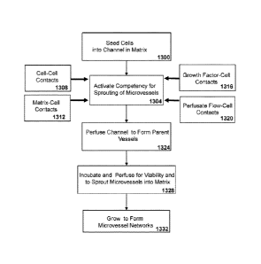
Referring, to FIG. 13A, a method for forming sprouting competent
cells and parent vessels is described. Cell types such as human umbilical
endothelial cells (HUVECs) are seeded at high-densities 1300 where the
majority of cells are in direct contact or nearly in contact with neighboring
cells in the 3D space of the channel. A subset of cells is in contact with the
matrix of the channel wall.
The seeding at high-density activates a competency for sprouting in
the cells 1304. Without being bound to a particular theory, it is believed
that
this phenotype is from cell-cell contacts that are present when cells are
seeded at a high-density which activates cellular signaling induced from
homophilic contacts between the cells 1308. It would also be expected that
heterotypic interactions between different cell types could also contribute to
activate the sprouting competent phenotype.
32
CA 02700371 2010-03-22
WO 2009/042639
PCT/US2008/077447
Additionally, contacts between the cells and the matrix components of
the channel wall may contribute to the activation of sprouting competency
1312. Further, there are contributions to activation of sprouting competency
from soluble growth factors 1316 contacts with cells. For example, growth
factors present in the perfusate medium, were previously shown to induce
sprouting (as shown in FIG. 7. for example). There
may also be
contributions from mechanical sensing of the perfusate flow by cells during
the seeding and perfusing of the cells 1320.
Cellular signal transduction events likely activate the sprouting
competent state 1304 observed for the cells. \AThen the cells are perfused in
the matrix channels they grow or come from cell migration forming parent
vessels 1324 with continuous lumens. The parent vessels are perfused and
incubated for viability and to sprout microvessels into the matrix 1328. The
trigger for the sprouting competence phenotype initially appears to be a
phenomenon related to the seeding density, but ongoing analysis will
delineate if this phenotype can be regulated further. Further growth leads to
the formation of complex 3D microvessel networks 1332. In
some
embodiments microvessels networks from different parent vessels merge via
anastomosis.
Without being bound to a particular theory, one hypothesis is that the
sprouting competency phenotype is derived from the sum of contacts that
mediate cellular signaling that depends on the density of seeding.
Additionally, contribution of the physical forces from seeding at high-density
can be evaluated for the sprouting competency phenotype. For example,
seeding of endothelial cells at high-density results in physical compression
where the endothelial cells are balled up during the process. Since
endothelial cells are typically spread out laterally in vessel formation this
is
not initially possible during seeding where cells are tightly packed together
and growth into the matrix may be favored triggering the sprouting
phenotype
Referring now to FIG. 13B, an alternate cellular perfusion device CPD
1350 is shown. The CPD 1350 provides for long term continuous perfusion
33
CA 02700371 2010-03-22
WO 2009/042639
PCT/US2008/077447
by having a single inlet fluid port 1354 and single outlet fluid port 1392 to
enhance functioning and efficiency of perfusion. A silicone layer 1366 is
sealed within a first slide 1370 and second slide 1374 using oxygen plasma
indicated by seal 1362. The resulting seal 1362 is watertight under pressure
that may be generated by long term perfusion.
The single inlet fluid port 1354 allows priming and seeding of cells at
high-densities via injection into a priming chamber 1378. A conduit 1382 is
coupled to a glass capillary mandrel 1384 within a collagen matrix chamber
1390. Collagen can be injected into the matrix chamber 1390 around a glass
capillary mandrel 1384 forming the matrix in the collagen chamber 1390.
Removal of the glass capillary mandrel 1384 through the conduit 1382
provides a channel 1388 within the collagen matrix. Flow of a perfusate
medium 1394 proceeds into the fluid inlet port 1354 through conduit 1382 to
the channel 1388 across the matrix chamber 1390 and to a second priming
1.5 chamber 1378 to the outlet port 1392 and to a waste reservoir 1396.
More
than one channel may be present in alternate example CPDs.
Referring now to FIG. 13C to FIG.13E, the seeding of the CPD is
schematically depicted. In FIG. 13C a top view of the alternate CPD 1350 is
schematically depicted. Note the orientation is opposite of that in FIG. 13B.
The CPD 1350 is shown with the mandrel 1384 within the matrix chamber
1390 that can be filled with collagen. The CPD contains a silicone layer
1366 that is sealed with oxygen plasma between two glass slides 1370/1374.
Referring now to FIG. 130 collagen 1391 or equivalent matrix is injected into
the matrix chamber 1390 and allowed to gel around the mandrel 1384. The
mandrel is removed through conduit 1382 leaving a channel 1388. Cells 1
(e.g. HUVECS and other cell types) are seeded at high-density in a
perfusate medium 1394. Cells may be injected by a suitable means for
example by a syringe.
The perfusate flow is maintained by means of a pump or equivalent
device which moves the cells 1 into the channel 1388 where flow is stopped
briefly for about 45 minutes allowing the cells to adhere to the channel wall.
Growth by means of an incubator or equivalent device leads to the formation
34
CA 02700371 2010-03-22
WO 2009/042639
PCT/US2008/077447
of a sprouting parent vessel within the channel (not depicted). Referring now
to FIG. 13E the CPD 1350 is shown configured once perfusion is resumed
through the cells 1 forming the parent vessel. Here, the inlet port 1354 is
shown at the bottom on the same side of the CPD as the outlet port 1396,
which facilitates handling of the device; but the location as seen on the
right
in FIG13C and FIG. 13D is also similarly functional. The incubator means
further allows for growing the sprouting microvessels until the microvessels
have formed networks.
The following examples were performed using a GPO (e.g. CPD
1350); equivalent device, or are schematically shown. Referring now jointly
to FIG. 14A, FIG, 14B, and FIG. 14 C, a high-density seeding method for a
matrix channel is schematically shown. In FIG. 14A, an example of a
collagen matrix is depicted 1400 together with a channel 1404. The channel
diameter may be made to any desirable size for angiogenesis study or
vessel growth. Cells, 1408, such as human umbilical vein endothelial cells
(HLIVEGs), alone or mixed with other cell types (e.g. SMG, pericytes,
fibroblasts, and precursors) are seeded at a high-density into the channel at
a specified flow rate in a perfusate medium 1412. In some example
embodiments endothelial cells or equivalents are present from a high-density
minimum of about 250 cells to a maximum of about 2000 cells per sq. mm
given a measured average cell size of about 18.0 microns diameter and
systematic correction factor of about 25. The
cells are thus highly
concentrated and exhibiting reduced flow characteristics. The flow rate of the
perfusate medium 1412 is set from a syringe pump or equivalent device and
can be adjusted to provide a specific flow rate and pressure for a given
channel. In certain embodiments a flow rate of 2 microliter/min is used which
corresponds to a shear stress of 1.2 dyn/cm2. Shear stress values of 0.75 to
dyn/cm2 have been reported as physiological and represent additional
embodiments. In other embodiments the flow rate could also be adjusted to
30 create shear stresses outside the normal limits for creating
pathological
conditions
CA 02700371 2010-03-22
WO 2009/042639
PCT/US2008/077447
In FIG. 14B, for some example embodiments the concentration is
sufficiently high that flow of the cells within the channel is significantly
reduced or stopped as a naturally occurring plug 1420 at the given flow rate
1424. In many cases the plug of cells is temporary and resolves without an
increase in flow rate or pressure. In other cases the flow rate and pressure
may be increased to remove the plug of cells. In certain examples the flow
of cells stopped in the plug 1420 for about one or two seconds and then
resumed 1425 without adjusting flow rate from the pump. In other examples
the flow rate was increased slightly just before or after a plug of cells
formed.
In representative embodiments the flow was then discontinued by switching
off the pump for about 30 to about 45 minutes allowing cells to adhere to the
channel wall. It is recognized that the concentration of cells, when seeded at
a high-density, is sufficiently high that flow of the cells reduces.
Also, evident is that physical stresses act on cells from the perfusate
flow and pressure as well as from contacts between cells and from contacts
between cells and the channel wall. These physical forces act as stimuli and
stress on the cells and are particularly evident when a plug of cells forms
stopping flow briefly. The aggregate physical stimuli can be altered,
increased or decreased, based on changes in the cell concentration,
pressure, and flow rate. Though it is believed the sprouting phenotype in
vitro is mediated via a mechanism related to the high-density of seeding, in
some cases the viscosity of the perfusate medium could be increased to
impart further physical stress effects. Such, aggregate stimuli is believed to
contribute to or initiate cellular events that mediate the activation of the
sprouting phenotype. Also, perfusion pressure appears to affect growth rate
and sprout maturation over time, It should be noted that sprouting in vivo is
not dependent on a seeding density or cells being in a spherical shape.
Sprouting in vivo does happen from flattened cells and is not dependent on
cell density. The right set of angiagenic factors, ECM, and perfusate would
be expected to stimulate normal flat endothelial cells or equivalents to
sprout
in our in vitro model similarly to what is observed in vivo.
36
CA 02700371 2010-03-22
WO 2009/042639
PCT/US2008/077447
Referring now to FIG. 14C, a side view through the channel is
depicted. After the incubation to allow cells to adhere to the channel wall
1404 the flow rate of the perfusate medium is increased 1432 to about 2
microliters per minute clearing cells from the channel 1428 that were are not
adherent to the channel wall 1404. After clearing, the channel wall 1404 is
lined with a layer of cells. The majority of cells is confluent and is in
contact
with other cells and the matrix. For illustration purposes the schematic view
through the side of the channel depicts cells lining the far side shown as
grey
shading 1434, whereas those cells on the top and bottom of the channel are
depicted schematically outlined in black 1436, 1438. In some regions cells
may be two or more layers thick 1436, but the most cells are present as
single layers 1438. In some cases cells may not be in contact with other
cells 1440, initially being subconfluent until later proliferation forms the
parent vessel,
Referring now to FIG. 15A, an example of a collagen matrix 1500 with
a representative channel 1510 of about 150 jtm diameter is depicted with a
top 1530 and bottom wall 1534. This channel 1510 was seeded at a high-
density with HUVECs as described in FIG, 14A-C. The collagen matrix was
formed with about 3 mg/ml final concentration. Higher or lower
concentrations of collagen or equivalent may be used in alternate
embodiments. In some examples alternate or hybrid matrix compositions
may be used.
Referring now to FIG. 158, the same matrix 1500 and channel 1510
are shown seeded with adherent human umbilical vein endothelial cells
1520, 1540, 1544 (HUVECs). In this example the cells were seeded at where
cells appear to be maximally packed into the channel at about 1000 to 2000
cells per Sq mm channel.
During seeding the perfusate flow stopped naturally forming a plug for
about one second that resolved without changing the flow rate with perfusion
continuing. The pump was at this point turned off stopping perfusion for
about 30-45 minutes, allowing the cells to adhere to the cell channel wall and
37
CA 02700371 2010-03-22
WO 2009/042639
PCT/US2008/077447
then subjected to ongoing perfusion. Subsequently, the pump was turned on
at the rate of 2 microliters/min which was used to clear away non-adherent
cells resulting in the channel lined with cells, either one 1520 or two or
more
1540 layers deep. In some cases a higher perfusate flow setting could be
used if necessary to facilitate flow and clearing of cells. Cells on the top
1540 or bottom 1520 are in focus and appear more refractile. The cells
visible in the central portion 1544 are somewhat out of focus representing
adherent cells on the near and far sides of the channel.
In FIG. 15C, the channel 1510 from FIG. 15B, is depicted
schematically (end view into channel), This represents the channel after
unbound cells have been washed out. The majority of cells 1520, 1540, 1544
are in direct contact with each other or with the channel wall 1530/1534,
forming a confluent sleeve of cells that are in most cases one layer thick.
Some regions may include two or more layers of cells 1540. In some cases
regions may be present where cells are nearly in contact with other cells and
are subconfluent 1550. Subsequent cellular proliferation will typically cover
these regions as the parent vessel grows.
Referring now to FIG. 16, an example of the activation of sprouting
competency for cells (HUVECs) is shown. The top panel shows a channel
1610 within a collagen matrix that has been seeded with a plurality of cells
1620 in a cellular density gradient 1630. The cellular gradient was created by
stopping the influx of cells prematurely, thus there was less cell coverage
per
volume of channel at the upstream end of the channel 1604 and more
concentrated cells in the downstream end 1608. The cells were allowed to
adhere for about 45 minutes and then were subjected to perfusion. Parent
vessels within intact lumens typically form quickly, within minutes, and
appear to form almost instantaneously when cells are seeded at high-density
concentrations. A complete monolayer is then formed when the cells attach
and stretch out, usually occurring in about 30-60 minutes. When a lower cell
concentration is used, it takes longer for a complete monolayer to form.
Sprouting of microvessels from parent vessels also depends on the
density of seeding. In high-density seeded parent vessels, the first minuscule
38
CA 02700371 2010-03-22
WO 2009/042639
PCT/US2008/077447
sprouts seen as merely cellular protrusions are visible after a few hours.
Larger sprouts usually develop during the first 2-3 days after seeding.
The center 1600 of the cellular density gradient is where the dramatic
sprouting phenotype is first activated and observable. It can be seen in the
top panel at day 1 of growth the majority but not all of the cells 1634 are in
contact with neighboring cells in the 3D space within the cannel Cells 1620
are also in contact with the channel wall.
The lower panel shows a parent vessel 1640 after 12 days of
growth with perfusion in the same channel 1610. The beginning of dramatic
sprouting of microvessels is observed from the middle region 1644 of the
parent vessel. This region corresponds to the cellular density indicated by
the bar 1600 in the top panel. Even more dramatic sprouting is observed
more upstream 1612, whereas the downstream end of the parent vessel
corresponding to lower density of cells shows no sprouting 1660. Sprouting
of microvessels continues and proliferation increases as the density of
cellular seeding increases 1650. The demarcation between the quiescent
domain and sprouting domain 1664 is clear and striking correlating with
seeding density. In most cases low density seeding resulted in quiescent
parent vessel's that do not proliferate and sprout microvessels. This
observation suggests that a threshold density of seeding triggers the
phenotype.
Estimation of the cellular density that triggers activation of the cells
was addressed further in quantitative experiments (e,g. see FIG 20A-F and
FIG 21A-B)
It is possible cells seeded below this density may retain some reduced
capacity to sprout as microvessels, In addition to the cell-cell contact
trigger
the composition of the perfusate also is believed impart competency for
sprouting. Growth factors present in the perfusate medium may act
synergistically with cellular contact signaling to mediate the phenotype.
Additionally, the cell matrix contacts s also may contribute to the phenotype.
Further, the physical forces from perfusate flow, pressure, and stress from
plug formation may also contribute to the activation of the sprouting
39
CA 02700371 2010-03-22
WO 2009/042639
PCT/US2008/077447
competency in cells. However, the cell-cell contact trigger appears to
contribute significantly to the activation of the sprouting competence
phenotype.
Referring now to FIG. 17, shown are examples of two sets of tandem
parent vessels derived from high-density seeding that are undergoing
anastomosis to form complex 3D microvessel networks. Individual CPD's
were incubated with perfusion over time and processed at time points with
the longest ending at 5 weeks. In most experiments channels were about
500 microns apart, but additional configurations were also examined, The
lei
maximal distance between channels that microvessels can traverse has not
been determined. However, microvessels should be capable of growing
towards the other parent vessels from over 500 microns to about several
millimeters.
Depicted are parent vessels 1710, 1720 growing from conduit 1704,
after one week 1700 and three weeks 1740. After the one week of growth
1700 the first vessel 1710 and second vessel 1720 are observed expanding
in diameter with their associated microvessels 1730 sprouting to form the
microvessel network between the two vessels. In a similar assay 1740, after
3 weeks the microvessel network 1750 is merged via anastomosis and
remains viable and capable of perfusion. The parent vessels 1760, 1770
can be seen, but are almost completely merged into the microvessel
network. In some examples the microvessel network merged to such an
extent that a cavity formed, however the network was still capable of being
perfused through the micovessels.
The incubation time required until the microvessel networks merge via
anastomosis is dependent on the original placement and distance between
the channels. Perfusion of tandem parent vessels resulted in the formation
of sprouting and complex 3D microvessel networks. Sprouting microvessels
grew in all 3D from the parent vessels. If parent vessels were originally
close
together the sprouting microvessel networks usually anastomoze into a
larger merged microvessel network that remained viable and competent for
perfusion.
CA 02700371 2010-03-22
WO 2009/042639
PCT/US2008/077447
Periods of up to five weeks with ongoing continuous perfusion have
been examined. A majority of cells throughout the parent vessels and
complex and extended microvessel networks remain viable as assayed with
Live/Dead fluorescence viability staining. Useful stains such as Live/Dead
are commercially available from, for example, Invitrogen Corp, of Carlsbad
CA, Overall, sprouting does slow over time likely reflecting limits on in
vitro
cultivation of the HUVEC primary cell cultures.
Sprouting microvessels likely grow and also regress depending on
nutrients, cellular signals, and culture conditions (e.g. presence or absence
of serum and specific growth factors). The stability of newly formed
microvessels and maturation into more mature vessels can be assessed by
methods of this disclosure using endothelial cells and additional cells types.
Composite microvessels comprising endothelial cells have been shown to be
stabilized by culture conditions and the presence of support cells. For
example growth factors such as VEGF, IGF-1 with serum free conditions
have been shown to promote angiogenesis and increased short term stability
of capillary-like networks in vitro (French, Lindemann et at, 2001).
Similarly, it
has been shown that addition of perivascular cells such as pericytes and
smooth muscle cells can stabilize such newly formed capillaries and aid their
maturation (Frerich. Lindemann et al. 2001). It is feasible addition of
additional cell types such as endothelial (vascular) progenitor cells or stem
cells coupled to defined culture condition in perfusates could also aid the
stability and maturation of composite microvessels.
Referring now to FIG, 18, parent vessels grown after one to eight
days of !urn inal perfusion are shown in several adjacent panels to illustrate
additional growth characteristics. Each CPD used to grow parent vessels
was handled similarly and processed for imaging of each parent vessel
1800, 1810, 1820, and 1830, at the indicated day. Each parent vessel is
perfused from conduit 1804 visible in some of the panels, The first panel
after day one of perfusion shows the parent vessel 1800 with only nascent
sprouting of microvessels 1808. In the next panel after day five of perfusion
the vessel 1810 shows robust sprouting of microvessels 1840. The visible
41
CA 02700371 2010-03-22
WO 2009/042639
PCT/US2008/077447
increase in diameter of the parent vessel 1814 is also evident. In the next
panel by day six of perfusion the parent vessel 1820 appears to have
reached an increase of about twice the original 150 micron diameter. It
appears proliferation of cells of the parent vessel encompasses the conduit
1804 growing over the ends 1824. The final panel after eight days of
perfusion shows that the parent vessel 1830 continues the sprouting of
microvessels 1840 and has continued to increase slightly in diameter. Also
the growth of the vessel over the end of the conduit 1804 is evident 1834
The expansion in diameter of each parent vessel is believed to be
both from invasion and growth of cells within the collagen matrix and from
responses of the vessel to the pressure of the perfusion flow. The degree of
cellular proliferation and sprouting was observed to be continuous over time
but did slow somewhat after several weeks of incubation. The slowing of
growth and sprouting may be due to the limited lifespan of HUVECs in vitro,
Referring to FIG, 19, shown are confocal 3D reconstruction images
from a representative microvessel network. The microvessels networks 1900
were grown using the high-density seeding methods described previously.
The sprouting microvessels were labeled with rhodamine labeled wheat
germ agglutinin to visualize the membrane structure of endothelial cells in
the microvessels and with the fluorescent DNA stain 4', 6-diamidino-2-
phenylindole (DAP1) to show nuclei.
In panel A, the microvessels 1910 are seen to be branched with intact
with unobstructed patent lumens based on the 3D tube structures and
perfusion. In panel, B, a higher magnification of microvessels 1920 is
depicted with an intact tubular vessel structure. The nuclei 1930 of
individual
endothelial cells are also shown for this sample, Branches from the
microvessel are evident 1940 that are intact with unobstructed patent lumens
with nuclei. The structure of the microvessels is consistent with viability as
assessed by staining and capacity for perfusion.
42
CA 02700371 2010-03-22
WO 2009/042639
PCT/US2008/077447
Quantitative Analysis of Sprouting
Referring, now jointly to FIG. 20A-FIG 20F and FIG. 21A-FIG 216, a
series of assays were done to with quantitative image analysis to determine
the minimal and maximum seeding density that triggers the sprouting
competency phenotype as well as aspects of sprout growth. Endothelial
cells were seeded as described previously in a CPD1350 and incubated to
form sprouting parent vessels. Samples were examined at time points after
seeding measured in hours (h) to examine both shorter term and longer term
incubation effects on sprouting. Growth of sprouting parent microvessels
was analyzed for incubation experiments from up to 96 h with data analyzed
at 0, 24h, 48 h, 72h and 96 hours (h) post seeding. The minimum and
maximum cell seeding densities that provided sprouting were determined
together with measurements of the average sprout length along the parent
microvessel position.
Cell seeding density measurements were performed by analyzing the
video image data for mean greyscale value (GSV) along the length of the
vessel. The images analyzed were acquired using transmission dark field
microscopy with a 4 x 0.10 NA objective lens. A region of interest (ROI) of
100 pixels wide was selected every 100 pixels along the length of the vessel
to sample the mean GSV within each box. To compensate for uneven
background illumination, another similar set of ROls was used to sample the
background surrounding the vessel The background corrected mean GSV
was plotted versus position along the vessel. To calculate cell seeding
density, the relationship between number of cells and mean greyscale value
within a given ROI was established. The relationship between cell seeding
and GSV was found to be approximately linear within the range of cell counts
measured (data not shown). The slope of the best fit line was used in
calculations to relate mean GSV to cell seeding density.
Referring now to FIG, 20A, the plot of the initial cell seeding density
versus position along the parent vessel is depicted 2000. The minimum cell
seeding density was established by plotting sprout length versus cell seeding
density, where the sprout length equals zero for the best fit lines of this
plot,
43
CA 02700371 2010-03-22
WO 2009/042639
PCT/US2008/077447
this is the true minimum cell seeding density. These values are 362 cells per
sq. mm for 24 h, 340 cells per sq. mm, for 48 h, 317 cells per sq. mm, 293
cells per sq. mm, 96 h. The minimum actual seeding experiments for cell
seeding density will always be larger than the values quoted above (e.g. 293
cells/sq. mm for 96 h) and plotted in FIG. 21B.
Referring now jointly to FIG. 20B to FIG 20F, the microscope images
of sprouting parent microvessels from the short term growth experiments
summarized in FIG, 20A (above) In FIG. 20B the initial cell seeding 2008
with an overlay of the cell seeding density 2012 is shown, In FIG, 20C
sprouting parent microvessels after 24 h incubation after seeding is shown
2016. Representative sprouts are shown in the middle portion of the parent
microvessel 2018. A viable sprout for the lowest density region is indicated
by the white line 2020. The same parent vessels are shown after 24 h 2024,
72 h 2032, and 96 h 2040. The minimum initial seeding density where a
viable sprout was found is also shown by white lines for each 2028 (48 h),
2036 (72 h), 2044 (96 h). The overall sprout length increases with time as
seen by representative sprouts from the middle of each parent microvessel
2026 (48 h), 2034 (72 h), 2042 (96 h). In FIG 20F an air bubble is visible
just
to the left of the white line 2044 for the minimum density for a viable
sprout. It
can be seen that sprouting is fairly uniform over the domain where sprouting
is evident.
The data from experiments for short term growth experiments
established the minimal seeding density required for sprouting. The minimum
value for sprouting was about 250 attached cells per sq. mm. This minimum
can be compared to the peak measured value of about 1000 to 2000 cells
per sq, mm, where the cells appear visually to be maximally packed within
the conduit or channel during seeding. The measured 1000 to 2000 cells per
sq. mm agrees with theoretical maximum values.
Referring now to FIG. 21A and FIG. 216, the average sprout length
was also determined for the growth of parent vessels from 0 to 96 h. In FIG.
21A the sprout length 2100 is shown for 24 h, 2116, 48 h, 2108, 72 h, 2112,
44
CA 02700371 2010-03-22
WO 2009/042639
PCT/US2008/077447
and 96 h, 2116. The sprout length agrees reasonably well with direct
measurements from the microscope images.
Referring, now to FIG. 218, a graph of the average sprout length
versus the initial seeding density is show 2120. The best fit line for each
time point analyzed is also shown 24 h, 2124, 48 h, 2128, 72 h, 2132, and 96
h, 2136. The minimum cell density data can be found from where the best fit
line intersects the x-axis, the initial seeding density (number of Cells per
sq.
mm). An expanded view would show the intersections to be the values of
362 cells per sq. mm for 24 h, 340 cells per sq. mm, for 48 h, 317 cells per
sq. mm, 293 cells per sq, mm, 96 h.
It should be noted there may be a misleading factor regarding
measurement of sprout length. As the inner diameter of a microvessel gets
larger this has not been taken into account in the current analysis. Thus, any
changes in diameter are included in the sprout length values,
Referring now to FIG 22, composite parent vessels consisting of
HUVECs and rat aortic smooth muscle cells (RASMCs) were examined. The
HUVECs were labeled with fluorescent dye (Cell Tracker Green) and seeded
at high densities and with methods described above in this disclosure where
the increased sprouting phenotype was evident. After, growth for about 24
h, the HUVECs formed sprouting parent vessels which were subjected to
ongoing perfusion with a growth medium. RASMCs were seeded into the
HUVEC parent vessels and were observed to adhere to the microvessel wall
and subsequently to migrate through the microvessel wall assuming a
perivascular position. In FIG 22 an overlay of fluorescent and bright field
images is shown 2200 of representative composite HUVEC and RASMC
sprouting parent microvessels, The parent microvessels are seen with dark
staining 2210, while perivascular RASMCs appear clear 2220. The migration
of the RASMCs to the perivascular position around the HUVEC parent
microvessels is consistent with their known support role in vessel maturation
and stability,
CA 02700371 2010-03-22
WO 2009/042639
PCT/US2008/077447
Assays and Targets for Angiogenesis Research
The ability to dramatically activate HUVECs for a sprouting competent
phenotype provides for increased ability to screen for products that are
angiogenic or that are angiostatic within the perfusate, matrix, or that are
derived from normal, pathogenic (e.g. cancerous, virally infected), or
engineered cells and tissues. Monitoring the microvessel networks provides
an efficient measure where increased sprouting and microvessel growth
indicates an angiogenic effect and reduced sprouting and microvessel
growth indicates an angiostatic effect. Also the contribution of endothelial
cells, smooth muscle cells, pericytes, and fibroblasts together with
progenitor
cells and stem cells can be assayed for additional aspects of vessel
formation and function. Also, cancer cells can be tested for their angiogenic
potential by having them suspended in the matrix. Development and growth
of complex tissues can be better examined with improved vascularization
now available. The robust increase in sprouting of microvessels provides a
sensitive assay system.
The hypothesis that cell-cell mediated signaling is primarily
responsible for the activation of the sprouting phenotype can be tested by
examining candidate genes and their gene products known to facilitate
cellular signaling in homophilic endothelial cell adhesion. The contribution
of
cell-matrix mediated signaling, growth factor-cell mediated signaling, and
mechanical sensing mediated signaling related to flow of perfusate can also
be addressed to determine the overall cellular phenotype and behavior in
vessel formation. Further, the promise of the ability to regulate the
activation
of the sprouting phenotype provides even additional benefits for
angiogenesis models and research.
Endothelial Specific Markers
Target genes in endothelial cells can be genetically modified via
recombinant DNA methods to examine their contribution to cellular
phenotypes including but not limited to the activation of the sprouting
competency phenotype. Specific marker genes expressed in endothelial
46
CA 02700371 2010-03-22
WO 2009/042639
PCT/US2008/077447
cells are attractive targets for manipulation and testing in assays using
methods of this disclosure. Endothelium derived cell lines can also be
examined such as those derived from macrovessels and from rnicrovessels.
Endothelial cells display significant heterogeneity in vivo (Aird 2007).
Numerous genes preferentially expressed in either arterial endothelium or
venous endothelium have been identified. Arterial endothelial cells have
been shown to specifically express several genes including ephrinB2 (Gale,
Baluk et al. 2001), Delta-like 4 (0114) (Krebs, Xue et al. 2000), activin-
receptor-like kinase (Alkl ) (Seki. Yun et al. 2003), endothelial PAS domain
protein (EPAS1) (Tian, McKnight et al. 1997), Hey1 (Nakagawa Nakagawa
et al. 1999), Hey2 (Nakagawa. Nakagawa et al. 1999), neuropilin 1 (NRP1)
(Mukouyama, Gerber et al. 2005), and decidual protein induced by
progesterone (Depp) (Shin and Anderson 2005). Venous endothelial cells
have been shown to specifically express several genes including EphB4
(Gerety, Wang et al. 1999), neurophilin 2 (NRP2) (Yuan, Moyon et al. 2002),
COUP-TF11 (You, Lin et al. 2005), and class Ill ii-tubulin at the tip of
venous
valves (Kang and Lee 2006).
Each of these known genes could be obtained and genetically
engineered to assay the effect of over expression, gene dosage, mutations,
or loss of function, on endothelial cell function in angiogenesis using
methods presented in this disclosure. Sequence data is available for each of
these genes from the N1H Genbank genetic sequence database facilitating
such analysis Genbank is an annotated collection of all publicly available
DNA sequences (Benson. Karsch-Mizrachi et al, 2008).
Endothelial Cell Lines
Assaying subpopulations of endothelial cells from particular sources
or established endothelial derived cell lines provides for advances in
understanding angiogenesis and in regulating growth of vessels. For
example, endothelial cell lines derived from either arterial macro or micro
47
CA 02700371 2010-03-22
WO 2009/042639
PCT/US2008/077447
vessel sources could be selected to form microvessels using CPDs and
methods of this disclosure. Candidate cell lines with extended lifespan or
that
are immortalized could additionally be characterized for normal karyotypes
and non-tumorgenic phenotypes as well as expression patterns of adhesive
proteins and coagulation molecules (Bouis, Hospers et al, 2001). Endothelial
cell lines made from human umbilical vein (HUVEC) that have extended
lifespan, are characterized to varying degrees, but that are not immortalized,
exist including ESV233, ESVSF108, ESV2010 (INS/EGF), ESV2010-GF
(Hohenwarter, Jakoubek et al. 1994). Several immortalized endothelial cells
lines exist that are well characterized including macro vessel derived line
EA,hy926 (EdgeII, McDonald et al. 1983), macrovessel derived line EV304
(Takahashi, Sawasaki et al. 1990), and microvessel derived line HMEC-1
(Ades, Candal et al. 1992). Additionally, cell lines exist and new lines could
also be generated for study,
Endothelial cell lines with extended lifespan or that are immortalized
could be assayed for function in forming vessels and in angiogenesis using
methods presented in this disclosure. Use of candidate endothelial lines
offers the practical advantage of their extended life span in vitro, reported
stable karyotype, and associated phenotypes. Additionally, such cell lines
could be further genetically modified or engineered to exploit their existing
cellular phenotypes. Also, endothelial cells can be isolated from patients to
test how they respond to certain drugs using personalized medicine
approaches with methods of this disclosure. The same is true for cancer
cells,
Additionally, similar cells and cells line derived from lymphatic tissue
could be utilized in methods of this disclosure.
Cellular Adhesion and Signaling Pathways
The activated sprouting phenotype induces proliferation of
microvessels sprouting from the parent vessels. This phenotype is likely
related to cellular responses to proliferative signals. During angiogenesis
capillary sprouts grow from larger vessels that contain contact inhibited
cells.
48
CA 02700371 2010-03-22
WO 2009/042639
PCT/US2008/077447
Genes and their protein products from adhesion and signaling pathways
associated with contact inhibition are candidates to be assayed via methods
of this disclosure to gain insights into vessel formation and angiogenesis.
The activation of the sprouting competency observed with HUVECs is
dependent of the seeding density probably from cell-cell contacts.
Contributions from cell-matrix-contact, as well as cell-growth factor contacts
and even mechanical signaling from seeding and perfusate flow are also
potentially involved in activating the sprouting competency. All of these
stimuli sources implicate signaling and may be integrated to mediate the
overall cellular phenotype and behavior.
Adherens junctions play important roles between endothelial cells for
contact inhibition of cellular growth and paracellular permeability to
circulating solutes and leukocytes Tight junctions are also involved in
cellular adhesion and are responsible for regulating barrier functions and
polarity (Wheelock and Johnson 2003; Bazzoni and Dejana 2004),
Additionally, other adhesion proteins, such as the platelet endothelial cell
adhesion molecule, PECAM-1, found at endothelial intercellular junctions,
are involved in cellular adhesion and cellular signaling.
Endothelial cells form unique cell-cell adherens junctions containing
an endothelial specific cadherin, VE-cadhenn. Endothelial cells also express
N-cadherin, T-cadherin, and a related protein named VE-cadheren-2. VE-
cadherin and the other cadherins expressed in endothelial cells transfer
information intracellularly through interactions with a complex network of
cytoskeleton proteins and signaling molecules. VE-
cadherin forms
complexes with ii-catenin, plakoglobin, and p120 catenin and likely contacts
the actin cytoskeleton in structures that are similar to typical adherens
junctions The formation of endothelial adherens junctions, maintenance,
and disassembly are important points of regulation for vessel formation and
function.
Signaling pathways associated with endothelial adherens junctions
include the wnt pathway, Rho GTPases and signaling through receptor
49
CA 02700371 2010-03-22
WO 2009/042639
PCT/US2008/077447
tyrosine kinases and are candidates for further study of the activation of the
sprouting competency phenotype. It follows that genes and protein products
from these signaling pathways in addition to adherens junctions components
VE-cadherin, N-cadherin, T-cadherin, and VE-cadheren-2, as well as the
interacting proteins of VE-cadherin 13-catenin, plakoglobin, and p120 catenin,
as well as PECAM-1, are candidates for manipulation and for assaying in the
microvesseel network assay of this disclosure. Further, downstream events
that are unknown could be elucidated using the microvessel assays and
methods of this disclosure.
Components of tight junctions are also known and include
transmembrane adhesive proteins, intracellular molecules, and signaling
pathways. Occludin, claudins (e.g, claudin 1 and 2, and other claudin family
members), junctional adhesion molecules (e.g. JAM-A, JAM-B, JAMC) are
involved in tight junction adhesive functions. Intracellular components of
tight junctions include membrane-associated guanylate kinases family
members (MAGUK) including ZO-1, and related ZO-2, and ZO-3, along with
non-MAGUK proteins of AF-6/afadin, Par-3/ASIP. and MUPP-1 (Bazzoni and
Dejana 2004),
Manipulation of tight junction components may yield
important information about the activation of sprouting competency and aid
in determining barrier function of such vessels. Also; downstream events
that are unknown could be elucidated using the microvessel assays and
methods of this disclosure.
Each of the known genes of adherens junctions and tight junctions or
associated signaling components could be isolated without undue effort and
genetically engineered to assay the effect of over expression, gene dosage,
mutations, or loss of function on endothelial cell function in angiogenesis
using methods presented in this disclosure. Sequence data is available for
each of these genes from the NIH Genbank genetic sequence database
facilitating such analysis.
Morphogenesis of Endothelial Cells in Angiogenesis and Vasculogensisis
CA 02700371 2010-03-22
WO 2009/042639
PCT/US2008/077447
Endothelial cell morphogenesis includes angiogenesis, where vessels
form from existing vessels, as well as vasculogenesis, where vessels form
from endothelial cells (EC) or EC precursors and progenitor cells in tissues
or from delivery via circulation. Endothelial cell morphogenesis also includes
cases where microvessels regress based on signaling input and regulation.
The activated sprouting phenotype induces proliferation of
microvessels sprouting from the parent vessels. This phenotype is also likely
related to endothelial cell morphogenesis from contacts between endothelial
cells and also from contacts between endothelial cells and the extra cellular
matrix (ECM). Endothelial cell morphogenesis in forming new vessels has
been shown to be affected by the matrix-integrin-cytoskeletal (MIC) signaling
pathway (Review, Davis, Bayless et al. 2002).
This MIC pathway starts with interactions between cells via cell-cell
junctional contacts and from interactions between cells and the extracellular
matrix components. Involvement of integrins (e.g. a2f31 a131, avp, a501:
a631) and extracellular matrix interactions, participation of cytoskeletal
elements (e.g. actin, microtubule, and intermediate filament cytoskeletons)
and downstream signaling and regulatory molecules (e.g. Rho GTPases,
Rho A, Racl, Cdc42, PAK-1, lateral inhibitory factors, ECM degrading
proteinases) all contribute to the ability of endothelial cells to form tube
structures, sprout, and branch as new microvessels during morphogenesis.
Membrane-type matrix metalloproteinases (MT-MMPs) that degrade
ECM are postulated to participate in endothelial cell morphogenesis
(Hiraoka, Allen et al. 1998); (Notary, Allen et al. 2000). Candidates for
study
and manipulation are MMP-1, MMP-2, MMP-9, as well as other equivalent
MT-MM Ps (Davis, Bayless et al. 2002). Also, inhibitors that block MT-MM Ps
such as the protein TIMP-2, and the chemical MMP inhibitor GM6001 have
been shown to block endothelial cell morphogenesis when endothelial cells
are suspended in collagen (unpublished data, Davis, Bayless et al. 2002)).
TIMP-2 inhibits endothelial cell proliferation and is a TIMP family member of
51
CA 02700371 2010-03-22
WO 2009/042639
PCT/US2008/077447
natural metalloproteinase inhibitors. The chemical GM6001 is an inhibitor of
collagenases and is available from Millipore.
Lateral inhibition is a phenomenon where subsets of cells produce
factors that inhibit neighboring cells which can result in selective
differentiation. Such inhibitory factors could play a role in endothelial
sprout
density (Davis. Bayless et al 2002) For example, molecules shown to
regulate lateral inhibition are the Notch ligands Jagged, and Delta (Lindsell,
Boulter et al. 1996; Zimrin, Pepper et al. 1996; Bell, Mauila et al. 2001).
Also, the Notch 1 and Notch4 receptor have been shown to be present in
endothelial cells (Zimrin. Pepper et al. 1996; Uyttendaele, Closson et al.
2000: Lindner, Booth et al. 2001). These factors are candidates for study
and manipulation to determine their overall role in endothelial
morphogenesis.
Manipulation of MIC components and assay of individual products
from the MIC and downstream pathways is feasible in methods of this
disclosure. Many genes and gene products associated with MIC signaling
and endothelial cell morphogenesis are known and could be assessed in the
microvessel assay for contribution to sprouting competency and
angiogenesis.
Known MIC pathway genes or associated signaling and regulatory
components could be isolated without undue effort and genetically
engineered to assay the effect of over expression, gene dosage, mutations,
or loss of function on endothelial cell morphogenesis using methods
presented in this disclosure Sequence data is available for many of these
genes from the NIH Genbank genetic sequence database facilitating such
analysis.
Screening for Products Affecting Angiogenesis
Referring now to FIG. 23, shown schematically is an assay for
screening for cells (C), products (P), and tissue (T) that affect parent
vessels,
microvessel sprouting, and microvessel network formation. Utilizing a CPD
such as CPD 1350, CPD 900, or equivalent, and methods of high-density
52
CA 02700371 2010-03-22
WO 2009/042639
PCT/US2008/077447
seeding to activate the sprouting competent phenotype, responses of
microvessel sprouting as well as the formation of microvessel networks can
be examined, The networks of microvessels can be used to screen for
angiogenic and angiostatic factors in the matrix or perfusate medium by
monitoring the formation of the microvessel network, where increased growth
of the network indicates an angiogenic factor and decreased growth of the
network indicates an angiostatic factor.
Candidates, including Cells, (C) products (P), and tissue (T) can be
assayed either dispersed throughout the matrix, or locally concentrated.
Alternately, cells (C) and products (P) can be added to the perfusate
medium. In many embodiments bioactive products that may be released
from the different candidates being assayed can be assessed. Bioactive
means that the candidates affect growth of sprouting microvessels in some
discernable manner, for example by providing for measurable differences in
growth,
Cells can be endothelial cells, smooth muscle cells, pericytes,
fibroblast cells, progenitor cells, stem cells, muscle cells, liver cells,
lung
cells, skin cells, epithelial cells, human cells, animal cells, plant cells,
eukaryotic cells, genetically engineered cells, genetically modified cells,
diseased cells, virally infected cells, and cancerous cells. Products can
include growth factors (e.g. basic fibroblast growth factor (bFGF), vascular
endothelial growth factor (VEGF), phorbol esters (e.g. phorbol 12-myristate-
13-acetate (PMA)), platelet-derived growth factor (PDGF), connective-tissue
growth factor (CTGF), heparin-binding growth factors (HB-EGF), interleukin-
8 (IL-8), long R3 insulin-like growth factor (R3IGF-1), insulin like growth
factors (e.g. IGF-1), human epidermal growth factor (hEGF), connective-
tissue growth factor (CTGF), heparin-binding EGF like growth factor (HB-
EGF), cytokines, anglopoietins, placental growth factor, various chemokines
(e.g. SDF-la), TGF-f3, soluble mitogens, cellular adhesion proteins (e.g.
fibronectin, vitronectin, fibrin, arginine-glycine-aspartate motif (RGD)
proteins, RGD-peptides, gelatin, collagen, and different collagen sub-types),
53
CA 02700371 2010-03-22
WO 2009/042639
PCT/US2008/077447
synthetic peptides, and equivalent bioactive compounds. Tissues can be
healthy, cancerous, virally infected, or genetically modified or engineered.
At least one cell type 2304 can be seeded at a high-density 2313
through conduit 2308 into a channel 2316 within a matrix 2312 of a CPD
2300, The at least one cell type can be HUVECs, or combinations of cell
types (e.g. smc, pencytes, progenitor cells, stem cells) some of which are
capable of being activated for competency for sprouting as microvessels
from parent vessels 2328, via cell-cell, cell-matrix, cell-growth factor, and
physical contacts from perfusate flow. Alternately, the cells 2336 can be
genetically modified or engineered to release bioactive products. Incubating
the seeded channels further allows the parent vessel to develop confluent
cell layers 2331.
A first perfusate medium 2320 can remove cells 2304 that do not
adhere to the channel matrix wall 2316 after about 45 minutes incubation,
The incubation time can be much shorter or omitted, depending on the
experimental conditions. The first perfusate medium 2320 or a second
perfusate medium 2332 also provides for growth of the parent vessel 2328.
In different embodiments the perfusate mediums can be of the same
composition or can be differently formulated as required. Cells (C), products
(P) or tissue (T) 2311 can be seeded into the matrix 2312 at various
locations either locally concentrated or dispersed. Alternately, cells (C) or
products (P) 2314 added to the perfusate medium 2320, 2332. Products (P),
for example angiogenic and angiostatic bioactive compounds, can also be
secreted from cells of the parent vessel 2328.
Referring now to FIG, 24A and FIG, 24B jointly, the response of
microvessel sprouting and network formation to added candidate cells (C),
candidate products (P), and candidate tissue (T) is depicted schematically
after cell seeding at a high density. A portion of a single parent microvessel
is depicted for illustration purposes only. Single, double, or complex arrays
of parent microvessels could be analyzed in different embodiments in a
series of CPDs.
54
CA 02700371 2010-03-22
WO 2009/042639
PCT/US2008/077447
In FIG. 24A and FIG. 2413, two CPDs are schematically shown with
different amounts of candidates, including candidate cells (C), products (P),
or tissue (T) candidates, concentrated locally. In FIG 24A, the CPD 2400 is
shown to include a matrix 2404 with a higher amount of candidate cells (C),
products (P), or tissue (T), 2408. Similarly, a higher amount of cells (C) or
products (P) 2412 may be added to the perfusate 2416. After incubation
with perfusion the effect of the addition of candidate (C), products (P), or
tissue (T) can be assessed by measuring 2428 the length of new sprouts
2420, 2424, An angiogenic effect from locally concentrated candidates will
lei result in increased and more robust sprouting 2420 close to the
candidates
being assayed, while sprouts distal to the candidates will show less growth
2424. Addition of higher amounts of cells (C) or products (P) 2412 to the
perfusate would be expected to increase sprout growth on all sides of the
parent vessel (not depicted). In FIG. 248, the CPD 2430 includes a lower
amount of candidate cells (C), products (P), or tissue (T) 2124, concentrated
locally, or similarly with lower amounts of cells (C), or products (P) 2438
added in the perfusate 2416. The sprouts would be expected to show less
growth 2450 for sprouts 2442 close to the candidates being assayed
compared to CPDs with higher amounts 2400. In some cases the sprouts
close 2442 and distal 2446 to the candidates may be similar in size. By
assaying a broad range of amounts for candidates the angiogenic effect can
be determined based on the degree of increased growth of new sprouts
compared to controls.
Referring now to FIG. 25A and FIG. 258 jointly, two CPDs are
schematically shown with different amounts of candidate cells (C), products
(P), or tissue (T) candidates, concentrated locally, In FIG 25A, the CPD
2500 is shown to include a matrix 2504 with a higher amount of candidate
cells (C), products (P), or tissue (T) 2508. Similarly, a higher amount of
cells
(C) or products (P) 2512 may be added to the perfusate 2516. After
incubation with perfusion the effect of the addition of candidate (C),
products
(P), or tissue (T) can be assessed by measuring 2528 the length of new
sprouts, 2520, 2524, An angiostatic effect from locally concentrated
CA 02700371 2010-03-22
WO 2009/042639
PCT/US2008/077447
candidates will result in decreased 2522 or even no sprouting 2520 close to
the candidates being assayed, while sprouts distal to the candidates will
show some or even normal growth 2524. Addition of higher amounts of (C)
or products (P) 2512 to the perfusate would be expected to decrease sprout
growth on all sides of the parent vessel (not depicted). In FIG 25B, the CPD
2530 includes a lower amount of candidate cells (C), products (P), or tissue
(T) concentrated locally 2534, or similarly with lower amounts of cells (C),
or
products (P) 2538 added in the perfusate 2516. The sprouts would be
expected to show more normal growth 2550 for sprouts 2542 close to the
candidates being assayed compared to CPDs with higher amounts 2500. In
some cases the sprouts close 2542 and distal 2546 to the candidates may
be similar in size indicating less or no angiostatic effect for candidates, By
assaying a broad range of amounts for candidates the angiostatic effects can
be determined based on the degree of inhibition of growth of new sprouts
compared to controls.
In alternate embodiments increasing amounts of locally concentrated
candidates could be assayed in a single CPO. Also, various combinations
could be assayed in different embodiments in the microvessel formation
assay. For example, only one parent vessel is depicted in the schematic, but
different embodiments could have two or more parent vessels with cells (C),
products (P), and tissue (T) placed at various locations in the matrix, either
dispersed or locally concentrated In alternate embodiments the cells (C),
products (P), or tissue (T) could also be added at different times before and
after microvessel sprouting Also, cells (C), products (P), or tissue (T) could
be added before and after the formation of complex microvessel networks
between one or more parent vessels. In still further embodiment's one
channel could be seeded with endothelial cells to form a parent vessel while
a second channel could be seeded with cancer cells or parenchymal cells or
stromal cells for tissue models or tissue engineering. Further, one would
recognize that a broad mix of channels could be seeded with a variety of cell
types that could be assayed (e.g. ECs-arterial, ECs-venous, lymphatic ECs,
parenchymal cells from liver or other tissues),
56
CA 02700371 2014-12-02
=
77501-45
= Anglogeneisis Assay
Referring now jointly to Fla 26A and FIG. 26B, shown is an 7
embodiment mimicking cell induced angiogenesis. In FIG 26A shown is a
. 5 bright field
image of two collagen channels from a CPD 2600, with one
seeded with HUVECs that has formed a sprouting parent vessel 2604 and
the second seeded with breast cancer cells 2608 of the BT474 cell line. The
HUVEC parent vessel shows sprouts 2610, 2620, 2630, 2640 growing
towards the breast cancer cells representative of angiogenic potential from
10 bioactive
products that may be released from the cancer cells. In FIG 268, a
corresponding fluorescence microscopy image of the same microvessels is
shown. The HUVECs were stained with a stain 2650 and the breast cancer
were stained cells with a different cellular stain 2660 before seeding (cell
tracker green CMFDA and cell tracker orange, CRMA, respectively, color not
15 depicted).
Thus, the sprouts 2610, 2620, 2630, and 2640 growing from the
HUVEC parent vessel are of endothelial origin could monitored for
angiogenic and angiostatic effects.
The invention has been described herein in considerable detail in
=.
order to comply with the Patent Statutes and to provide those skilled in the
. 20
art with the information needed to apply the novel principles of the present
invention, and to construct and use such exemplary and specialized
components as are required. However, it is to be understood that the
invention may be carried out by specifically different equipment, and devices
and reconstruction algorithms, and that various modifications, both as to the
. 25 equipment
details and operating procedures, may be accomplished without
departing from the true spirit and scope of the present invention.
In the event of an otherwise irreconcilable conflict with the disclosure of
references
cited herein, the present specification shall control.
57
CA 02700371 2010-03-22
WO 2009/042639
PCT/US2008/077447
References
Ades, E. W., F. J. Candal, et al, (1992). "VIMEC-1: establishment of an
immortalized
human microyascular endothelial cell line."J Invest Demiatol 99(6): 683-90.
Ai rd, W. C. (2007). "Phenotypic heterogeneity of the endothelium: H.
Representative vascular beds." Circ Res 100(2): 174-90.
Akhtar, N., E. B. Dickerson, et al. (2002). "The spongelMatrigel mgiogenesis
assay." Angioftnesis 5(1-2): 75-80.
Algire, G. H., H. W. Chalkley, et al (1945) "Vascular reactions of normal and
malignant tissues in vivo. L Vascular reactions of mice to wounds and to
normal and neoplastic transplants." j Nati Cancer 1nst 6: 73-85.
Andrade, S. 173., R. D. Machado, et al. (1997). "Sponge-induced angiogenesis
in mice
and the pharmacological reactivity of the neovasculature quantitated by a.
fluorimetric method." Mi_crovascites 54(3): 253-6.1.
Arthur, W. T., R. B. Vernon, et at (1998). "Growth factors reverse the
impaired
spraiting of microvessels from aged mice." .:Nilicrovase .Res 55(3): 260-70.
Ausprunk, D. H., D. R. Knighton, et al. (l.974). "Differentiation of vascular
endothelium in the chick chorioallantois: a structural and autoradiographic
study." Dev Bid l 38(2): 23748.
Bazzoni, G. and E. Dejana (2004), Endotheia ceHtoceli junctions; molecular
organization and we in vascular homeostasis." Physiol Rev 84(3): 869-901.
Bell, S. E,õA, Mayila, et al. (2001), "Di=fferentiai gene expression during
capillary
morphogenesis in 31) collagen matrices: regulated expression of genes
involved in basement membrane matrix assembly, cell cycle progression,
cellular dit7t7erentiation and G-protein signaling."3 Cell Sei 114Pt 15): 2755-
73.
Benson, .D. A., IL Karsch-Mizrachi, et al. (2008), "GenBank." Mud Acids Res.
36(suppl _1): D25-30.
BOU s, a, G. A. Hospers, et at. (2001). "Endothelium in vitro: a review of
human
vascular endothelial coil lines for blood vessel-related research "
Angiogenesis 4(2): 91-102,
Clark, E. R. and E. L. Clark (1939). "Microscopic observations on the growth
of
blood capillaries in the living mammal." Am 1- Anat 64: 251-301
Davis, G. E., K. J. Bayless, et al. (2002). "Molecular basis of endothelial
cell
morphogenesis in three-dimensional extracellular matrices." .Anat Roc
268(3): 252-75.
Davis, G. E. and C. W. Camarillo ( 1996). " An alpha 2 beta 1 integrin-
dependent
pinocytic mechanism involving intracellular vacuole formation and
coalescence regulates capillary lumen and tube formation in three-
dimensional collagen matrix." .B.R.(j.:01.Res 224(1): 39-51.
Edgell, C. J., C. C. N,,IcDonald, et al. (1983). "Permanent cell line
expressing human
factor WIT-related antigen established by hybridization." ,Proc Nati Acad Sci
US A 80(12): 3734-7.
Elsdale, T. and J. Bard (1972), "Collagen substrata for studies on cell
behavior." j
Cell Biol 54(3): 626-37.
Feder, J., S. C. Marasa, et al (1983). The formation of capillary-like tubes
by cal-17
aortic endothelial cells grown in vitro," .1 Cell Physiol 116(1): 1-6.
58
CA 02700371 2010-03-22
WO 2009/042639
PCT/US2008/077447
Fishman, j. A., G. B. Ryan, et al, (1975). "Endothelial regeneration in the
rat carotid
artery and the significance of endothelial denudation in the pathogenesis of
myointimal thickening." Lab Invest 32(3): 339-51.
Folkman, J. and C. Haudenschild (1980). "Angiogenesis in vitro," Nature
288(5791):
551-6,
Folk:man, J., C. C. Haudenschild, et al. (1979). "Long-term culture of
capillary
endothelial cells." :Proc Nati Acad Sci U S A 76(10); 5217-21,
French, 13., N, Lindemann, et al. (2001). In vitro model of a vascular stroma
for the
engineering of vasc.ularized tissues." JALJQtALMmillollcSurg 30(5): 414-
70.
French, B,, K Zuckmarnel, et al, (2008), "Maturation of capillary-like
structures in a
tube-like construct in perfusion and rotation culture." Int 3 Oral Maxillofac
Surg 37(5): 459-66.
Gale, N. W., P. Baluk, et al (2001). "Ephrin412 selectively marks arterial
vessels
and neovascularization sites in the adult, with expression in both endothelial
and smooth-muscle cells." Dev113io1230(2): 151-60.
Gerety, S. S., H. U. Wang, et al. (1999). "Symmetrical mutant phenotypes of
the
receptor EphB4 and its specific transmembrane ligand ephrin-132 in
cardiovascular development." Mol Cell 4(3): 403-14.
Gimbrone, M. A., jr. (1976). Culture of vascular endothelium. Pro g :Hemost
Thromb. 3:1-28.
Gimbrone, M..... in., ft. S. Cotran, et al. (1974). "Human vascular
endothelial cells
in culture. Growth and DNA synthesis," i Cell Biol 60(3): 673-84.
Gimbrone, M. A., Jr,, IR. S. Cottan, et al. (1974). "Tumor growth and
neovascularization: an experimental model using the rabbit cornea." J Nat!
Cancer Inst 52(2): 413-27.
Greenblatt, M. and P. Shubi (1968), "Tumor utgiogertesis: transtilter
diffusion
studies in the hamster by the transparent chamber technique." J Nati Cancer
hist 41(1)1111-24.
Hiraoka, N., E. Allen, et al. (1998), "Matrix metalloproteinases regulate
neovascularization by acting as pericellular ftbrinolysins." Cell 95(3): 365-
77.
Hohenwartet, 0,, A. Jakoubek, et al. (1994), "Expression of SV40 tumour
antigens
enables human endothelial cells to grow independently from foetal calf
serum and exogenous growth factors." J Biotechnol 34(2): 205-11,
Hotary, K., E. Allen, et al. (2000). "Regulation of cell invasion and
morphogenesis
in a three-dimensional type I collagen matrix by membrane-type matrix
metalloproteinases 1, 2, and 3," J Cell Biol 149(6): 1309-23.
Hoying, J. :B., CA. Boswell, et al. (1996). "Angiogenic potential of
micmvessel
fragments established in three-dimensional collagen gels." in Vitro Cell Dev
Biol Anim 32(7): 409-19,
Jaffe, E. A., R. L. Nachman, et al. (1973). "Culture of human endothelial
cells
derived from umbilical veins. Identification by morphologic and
immunologic criteria," J. Clin invest 52(11): 2745-56.
Jozaki, K., P. T. Marucha, et al. (1990). "An in vitro model of cell
migration:
evaluation of vascular endothelial cell migration." Anal Biochem 190(1): 39-
47.
59
CA 02700371 2010-03-22
WO 2009/042639
PCT/US2008/077447
Kang, J. and 1. Lee (2006): "Tull (class IR beta-tubulin) as phenotypic marker
of
lymphatic and venous valves." Cardiovasc Pathol 15(4); 218-21.
Koike, T., R. B. Vernon, et al, (2003). "Inhibited angiogenesis in aging; a
role for
TIMP-2." J Cierontol A Biol Sci Med Sci 58(9): B798-805.
Krebs, L T,, V. Xue, et al. (2000), "Notch signaling is essential for vascular
morphoqenesis in mice," Genes Dev 14(11): 1343-52,
Kubota, Y., HI. K. Klein.man, et al. (1988). "Role oflaminin and basement
membrane
in the morphological differentiation of human endothelial cells into capillary-
like structures," JCeI..Biol 107(4): 1589-98.
Kuzuya, Ni. and J. L. Kinsella (1994). "Induction of endothelial cell
differentiation
in vitro by fibroblast-derived soluble factors," Exp Cell .Res 215(2): 310-8.
Lindner, V., C. Booth, et al. (2001). "Members of the Jagged/Notch gene
families
are expressed in injured arteries and regulate cell phenotype via alterations
in
cell matrix and cell-cell interaction." Am I Pathol 159(3): 875-83,
Lindsell, E., J, IBoulter, et: al. (1996). "Expression patterns of Jagged,
Deltal,
Notch], Notch2, and Notch3 genes identify ligand-receptor pairs that may
function in neural development." Mel Cell Neurosci 8(1): 14-27.
Maciag, T., J. Kadish, et al. (1982). "Organizational behavior of human
umbilical
vein endothelial cells." J Cell Biol 94(3): 511-20.
Madri, J. A. (1982), "Endothelial cell-matrix interactions in hemostasis."
Prog
Hemost Thromb 1-24,
.Madri, J. A. and B. Ni. Pratt (1986). "Endothelial cell-matrix interactions:
in vitro
models of angiogenesis." Histochem Cytochem 34(1): 85-91
Madri, J. A., B. M. :Pratt, et al. (1988), "Phenotypic modulation of
endothelial cells
by transforming growth factor-beta depends upon the composition and
organization of the extracellular matrix."I Cell Bid 106(4): 1375-84.
.Madri, J. A. and K. S. Steno (1982). "Aortic endothelial cell migration. I.
Matrix
requirements and composition," Am J Pathol 106(2): 180-6.
Manoussaki, D , S. R Lubkin, et al, (1996), "A mechanical model for the
formation
of vascular networks in vitro." Acta Bi otheor 44(3-4): 271-82.
Marx, M., R. A. Perlmutter, et al, (1994). "Modulation of platelet-derived
growth
factor receptor expression in microvascular endothelial cells during in vitro
angiogenesis." Clin Invest 93(1); 131-9.
Menvin, J. R., J. M. Anderson, et all. (1990). "Transforming growth factor
beta I
modulates extracellular matrix organization and cell-cell junctional complex
formation during in vitro angiogenesis." J Cell Physio1 142(1): 117-28.
Montesano, R, and L. Orci (1985), "Tumor-promoting phorbol esters induce
angiogenesis in vitro." Cell 42(2): 469-77.
Montesano, R., L. Orci, et at (1983). "In vitro rapid organization of
endothelial cells
into capillary-like networks is promoted by collagen matrices." I Cell Elio'
97(5 Pt 1): 1648-52.
Montesano, R., M. S. Pepperõ et al. (1993). "Paracrine induction of
angiogenesis in
vitro by Swiss 3T3 fibroblasts." j Cell Su 105 ( Pt 4); 1013-24,
Mori, M., Y. Sadahira, et al. (1988), "Capillary growth from reversed rat
aortic
segments cultured in collagen gel," .Acta Pathol jpn 38(12): 1503-12.
CA 02700371 2010-03-22
WO 2009/042639
PCT/US2008/077447
Mukouyama, Y. S., H. P. Gerber, et at, (2005). "Peripheral nerve-derived VEOF
promotes arterial differentiation via neuro-pilin 1-mediated positive
feedback." Development 132(5): 941-52.
Nakagawa, 0., M. Nakagawa, et al, (1999). "HRT1, FIRT2, and HRT3: a new
subclass of bHLH transcription factors marking specific cardiac, somi tic, and
pharyngeal arch segments." Dev Biol 216(1): 72-84.
Nehls, V. and :D. Drenckhalm (1995), "A novel, microcarrier-based in vitro
assay for
rapid and reliable quantification of three-dimensional cell migration and
angiogenesis." Microvasc Res 50(3): 311-22,
Nehls, V. and R. Herrmann (1996). "The configuration of fibrin clots
determines
capillary morphogenesis and endothelial cell migration," Microvasc Res
51(3): 347-64.
NiCOSiaõ R: F., E. Bonannoõ et al, (1994). "Modulation of angiogene.sis in
vitro by
laminin-entactin complex." Dev Biol .1.64(1): 197-206.
Nicosia, R. F., E. Bonanno, et al. (1992). "Large-vessel endothelium switches -
to a.
micro-vascular phenotype during angiogenesis in collagen gel culture of rat
aorta." Atherosclerosis 95(2-3): 191-9.
Nicosia, R. F., S. V. Nicosia, et al, (1994), "Vascular endothelial growth
factor,
platelet-derived growth factor, and insulin-like growth factor-1 promote rat
aortic angiogenesis in vitro." Am .1 Pathol 145(5): 1023-9,
'Nicosia, R. F. and A. Ottinetti (1990). "Modulation of microvascular growth
and
morphogenesis by reconstituted basement membrane gel in three-
dimensional cultures of rat aorta: a comparative study of angiogenesis in
-matrigel, collagen, fibrin, and plasma clot." in 'Vitro Cell Dc v Biol 26(2):
119-28.
Nicosia, R. F., R. 'Fchao, et al, (1982), "Histotypic angiogenesis in vitro:
light
microscopic, ultrastructural, and radioautographic studies." in Vitro 18(6):
538-49.
Nicosia, R. F., R. Tam , et al, (1983) "Angiogenesis-dependent tumor spread in
reinforced fibrin clot culture." Cancer Res 43(5): 2159-66,
Nicosia, R. F. and G. P. Tuszynski (1994), "Matrix-bound thrombospondin
promotes
angiogenesis in vitro." .1 Cell Biol 124(1-2): 183-93
Passaniti, A,, R. M. Taylor, et al. (1992). "A simple, quantitative method for
assessing angiogenesis and antiangiogenic agents using reconstituted
basement membrane, heparin, and -fibroblast growth factor." Lab invest
67(4): 519-28,
Pepper, M. S., R. Montesano, et al, (1991), "Chondrocytes inhibit endothelial
sprout
formation in vitro: evidence for involvement of a -transforming growth factor-
beta." 1 Cell Physiol 146(1): 170-9.
Rosen, E. M., L. Meromsky, et al. (1990). "Quanti Union of cytokine-stimulated
migration of endothelium and epithelium by a new assay using microcarrier
beads." Exp Cell Res 1.86(1): 22-31,
Sage, E. H. and R. B. Vernon (1994). "Regulation of angiogenesis by
extracellular
matrix: the growth and the glue," J'Hypertens Suppl 12(10): S145-52.
Seki, T., 1. Yuri, et al. (2003). "Arterial endothelium-specific activin
receptor-like
kinase 1 expression suggests its role in arterialization and vascular
remodeling," Circ Res 93(7): 682-9.
61
CA 02700371 2010-03-22
WO 2009/042639
PCT/US2008/077447
Shin, D. and D. J. Anderson (2005), "Isolation of arterial-specific genes by
subtractive hybridization reveals molecular heterogeneity among arterial
endothelial cells." DeyDyri 233(4); 1589-604.
Takahashi, K., Y. Sawa saki, et al. (1990). "Spontaneous transformation and
immortalization of human endothelial cells." In Vitro Cell Dev Biol 26(3 Pt
1): 265-74.
'flan, H., S. L. McKnight, et al. (1997). "Endothelial PAS domain protein I
(EPAS1), a transcription factor selectively expressed in endothelial cells "
Genes Dev11(1): 72-81
Torres-Vazquez, J., M. Kamei, et at. (2003). "Molecular distinction between
arteries
and veins." Cell and Tissue Research 314(0: 43-59
Uyttendaele, H., V. Closson, et al. (2000). "Notch4 and Jagged-I induce
microvessel
differentiation a at brain endothelial cells," Mierova SC Res 60(2)1 91-103,
Vernon, R. B J. C. Angell , et al. (1992), "Reorganization of basement
membrane
matrices by cellular traction promotes the formation of cellular networks in
vitro." Lab Invest 66(5): 536-47.
Vernon, R. B. and M. D. Goodell (2002). "New technologies in vitro for
analysis of
cell movement on or within collagen gels." Matrix Biol 21(8): 661-9.
Vernon, ,R. B., S. L. Lara, et al. (1995), "Organized type 1 collagen
influences
endothelial patterns durinQ, "spontaneous anglogenesis in vitro": planar
cultures as models of vascular development" In Vitro Cell Dev Biol Anim
31(2): 120-31.
Vernon, R. B. and E. H. Sage (1999). "A novel, quantitative model for study of
endothelial cell migration and sprout formation within three-dimensional
collagen matrices." Microvasc Res 57(2): 118-33.
Villaschi, S. and R. F. Nicosia (1993), "Angiosenic role of endogenous basic
fibroblast growth factor released by rat aorta after injury." Am j Pathol
143(1): 181-90.
Wheelock, M J. and K :R. Johnson (2003). "CADHERINS AS MODULATORS OF
CELLULAR PHENOTYPE." Annual Review of Cell and Developmental
Biology 19(1): 207-235.
You, L. R., F. J. tin, et al. (2005). "Suppression of 'Notch signalling by the
COUP-
TF1.1 transcription factor regulates vein identity." Nature 435(7038): 98-104.
Yuan, L., D. MoyOrl, et at (2002). "Abnormal lymphatic vessel development in
neuropilin 2 mutant mice." Development :129(20): 4797-806.
Zimrin, A. B., M. S. Pepper, et al. (1996). "An antisense oligonucleotide to
the notch
ligand jagged enhances =fibroblast growth factor-induced angiogenesis in
vitro," I Biol Chem 271(51): 32499-502.
62