Note: Descriptions are shown in the official language in which they were submitted.
CA 02700766 2010-03-25
WO 2009/042224 PCT/US2008/011229
METHOD FOR EXTRACTION AND SURFACTANT ENCHANCED SUBSURFACE
CONTAMINANT RECOVERY
FIELI) OF THE INVENTION
[0001] The
present invention relates to methods and compositions for remediating
soil and groundwater. For
example, the present invention relates to methods and
compositions for removing contaminants from soil and groundwater by extracting
the
contaminants and assisting the extraction by provision of a gas under
pressure.
SUMMARY OF THE INVENTION
[0002] A method
according to the invention far decreasing the amount
of contaminant at a site in a subsurface, with at least a portion of the
contaminant being
extractable, can include the following. An
oxidant can be introduced prior to or
simultaneously with a surfactant into the subsurface. Alternatively, an
oxidant can be
introduced after a surfactant into the subsurface. Extractable contaminant can
be extracted
from the subsurface. The amount and/or distribution of contaminant in the
subsurface can be
characterized. The extracting of contaminant and the introducing of oxidant
and surfactant
can be coordinated to reduce contaminant to a target amount. A portion of the
contaminant
can be oxidizable. The oxidant can oxidize contaminant.
[0003] For
example, the extracting of contaminant and the introducing of oxidant and
surfactant can be coordinated to meet a predetermined goal and/or to optimize
one or more
parameters. For example, the extracting of contaminant and the introducing of
oxidant and
surfactant can be coordinated to minimize the amount of oxidant and/or
surfactant that must
be added to reduce the contaminant to a target amount. This may involve
extracting
contaminant for an extended period of time prior to adding oxidant and
surfactant. For
example, the extracting of contaminant and the introducing of oxidant and
surfactant can be
coordinated to minimize the time required to reduce the contaminant to a
target amount. This
may involve introducing oxidant and surfactant while extracting contaminant
from the start of
the process.
[0004] A method
according to the invention for decreasing the amount of a
contaminant at a site in a subsurface can include the following. An oxidant
and a surfactant
and/or cosolvent can be introduced into the subsurface. The surfactant can be
allowed to
solubilize or desorb the contaminant; the oxidant can be allowed to oxidize
the solubilized
contaminant in the subsurface; and the contaminant can be extracted from the
subsurface, so
1
CA 02700766 2010-03-25
WO 2009/042224 POTTS2008/011229
that the amount of the contaminant in the subsurface is substantially
decreased. The overall
rate of oxidization of the contaminant can be controlled to a predetermined
value; and the
overall rate of solubilization of the contaminant can be controlled to a
predetermined value.
For example, such control can be achieved by selecting the oxidant and
surfactant and/or
cosolvent and adjusting the concentrations of oxidant and surfactant and/or
oxidant, so that
the rate of oxidation of the contaminant is greater than, less than, or equal
to the rate of
solubilization of the contaminant.
[0005] The
surfactant and/or cosolvent can be introduced into the subsurface before
the oxidant is introduced into the subsurface. The surfactant and/or cosolvent
is introduced
into the subsurface after the oxidant is introduced into the subsurface.
[0006] A method
according to the invention can include allowing the oxidant to
liberate gaseous oxygen in the subsurface in the form of bubbles. The oxygen
bubbles can be
allowed to hydrodynamically scrub contaminant from soil particles in the
subsurface.
[0007] A method
for decreasing the concentration of a contaminant, such as a Light
Non-Aqueous Phase (LNAPL) contaminant, at a site in a soil can include the
following. A
remediation zone including the contaminant, e.g., the LNAPL contaminant, can
be selected.
An oxidant that produces a gas phase can be introduced into a subsurface
containing the soil
to establish an oxidation zone. The concentration distribution of oxidant in
the subsurface
can be identified to determine the extent of the oxidation zone. For
example, the
concentration of oxidant in the oxidation zone can be at least about 500 mg/L.
For example,
the concentration of oxidant in the oxidation zone can be in the range of from
about
500 mg/L to about 100 g/L. For example, the molar concentration of oxidant in
the oxidation
zone can be at least about 0.002 mol/L. For example, the molar concentration
of oxidant in
the oxidation zone can be in the range of from about 0.002 to about 0.4 mol/L.
For example,
the molar concentration of oxygen atoms in the oxidation zone can be at least
about 0.015
mol/L.
[0008] Under,
inside, upgradient, or downgradient of the oxidation zone, the
contaminant, e.g., the LNAPL contaminant, can be induced to flow toward an
extraction well
to establish an extraction zone. The contaminant, e.g., the LNAPL contaminant,
can be
further induced to flow to an extraction zone by increasing contaminant
solubility, mobility,
or solubilization and mobility using surfactants, cosolvents, or mixtures of
cosolvents and
surfactants. The extraction zone can include points in the subsurface at which
a fluid element
will eventually travel into the extraction well. The oxidation zone and the
extraction zone
-2-
CA 02700766 2010-03-25
WO 2009/0-1222.4
PCT/US2008/011229
can lie within the remediation zone. The oxidation zone can surround the
contaminant, e.g.,
the LNAPL contaminant, extraction zone. The oxidation zone can include oxidant
at a
concentration sufficient to destroy contaminants moving into the oxidation
zone, so that the
oxidation zone prevents the spread of contaminant beyond the remediation zone.
For
example, the oxidation zone can have a concentration of oxidant of at least
about 500 mg/L.
For example, the oxidation zone can have a concentration of oxidant in the
range of from
about 500 mg/L to about 100 g./L.
[0009] The oxidation zone can prevent the spread of contaminant beyond the
remediation and extraction zone. With a method according to the invention, the
amount of
contaminant in the soil can be substantially reduced.
[0010] A method for determining a subsurface contaminant remediation
protocol can
include the following. A soil sample, groundwater and contaminants can be
collected from
the subsurface. At least one target contaminant can be identified for
concentration reduction.
A surfactant, cosolvent, or mixture of cosolvents and surfactants can be
identified to
solubilize, mobilize, or solubilize and mobilize contaminants. An oxidant can
be selected for
injection into the subsurface to oxidize the target contaminant. The oxidant
can include an
oxidant that generates a gas phase upon its decomposition in the subsurface or
the oxidant
can be added as a gas. Further, in addition to the added oxidant, dissolved
gas under pressure
can be added to the subsurface to generate a gas phase. The behavior of the
gas phase, in
addition to the cosolvent-surfactant mixture or surfactant alone leads to
enhanced extraction
of the contaminant. Further, a dissolved gas under pressure can be added to
the subsurface to
generate a gas phase in addition to a cosolvent-surfactant mixture or
surfactant, which leads
to enhanced extraction of the contaminant. The spatial concentration
distribution of the target
contaminant can be determined. A hydrogeological property of the subsurface
can be
determined. The determined spatial concentration distribution of the target
contaminant and
the hydrogeological property can be used to determine a target depth for the
oxidant, gas
phase generating oxidant, or pressurized dissolved gas in liquid, cosolvent-
surfactant or
surfactant and injection site(s) of the above injectants, and an extraction
site for the
contaminant.
[0011] A method for reducing the concentration of a contaminant at a site
in a
subsurface can include the following. The contaminant can include a non-
aqueous phase
liquid (NAPL), a dense non-aqueous phase liquid (DNAPL), ancUor a light non-
aqueous
phase liquid (LNAPL). An extraction well can be provided in the subsurface. An
injection
-3-
CA 02700766 2016-06-03
fluid can be injected at an injection locus into the subsurface. The injection
fluid can include
hydrogen peroxide and/or another oxidant, or another gas phase generating
oxidant or
pressure dissolved gas in a liquid. The hydrogen peroxide and/or the other
oxidant or
dissolved gas can be allowed to decompose to liberate oxygen or dissolved gas
in the
subsurface. The other oxidant can be, for example, ozone, a persulfate, sodium
persulfate, or
a percarbonate. The injection fluid can include a liquid, e.g., water, and a
dissolved gas, e.g.,
oxygen and/or carbon dioxide, and the dissolved gas can effervesce as a
liberated gas upon a
decrease of pressure on the injection fluid in the subsurface. The injection
fluid can include a
compressed gas and/or a supercritical fluid under a pressure greater than
atmospheric. An
injected gas can include, for example, oxygen, carbon dioxide, nitrogen, air,
an inert gas,
helium, argon, another gas, or combinations of these. For example, the
injection fluid can
include dissolved carbon dioxide obtained from emissions of a fossil-fuel
consuming power
generation plant. The injection fluid can include a surfactant and/or a
cosolvent, for example,
the injection fluid can include VcruSOLT.m The injection fluid can include an
alkali carbonate
or bicarbonate, such as sodium bicarbonate. For example, the sodium
bicarbonate can be at a
concentration in a range of from about 1 g/L to about 200 g/L, or from about 8
g/L to about
16 g/L.
[0012] The injection
fluid can include an activator, for example, a metal activator, a
chelated metal activator, a chelated iron activator, Fe-NTA (iron -
nitrilotriacetic acid),
Fe(II)-EDTA (iron II - ethylenediaminetetraacetic acid), Fe(III)-EDTA (iron HI
-
ethylenediaminetctraacetic acid), Fe(II)-citric acid, Fe(III)-citric acid,
Fe(II)-EDDS (iron 11 -
ethylenediaminedisuccinic acid), or Fe(III)-EDDS (iron III -
ethylenediaminedisuccinic acid),
Fe(II)-DTPA (iron II - diethylenetriaminepentaacetic acid), or Fe(111)-DTPA
(iron III -
diethylenetriaminepentaacetic acid). For example, the iron of Fe-NTA can be at
a
concentration in the injection fluid in a range of from about 10 mg/L to about
5000 mg/L, or
can be about 250 mg/L. The injection fluid can include an antioxidant. The
oxygen and/or
the gas produced from reaction of the oxygen, hydrogen peroxide, and/or other
oxidant with
the contaminant, e.g., carbon dioxide, can be allowed to impose pressure to
force the
contaminant to flow through the subsurface toward the extraction well. The
contaminant can
be removed from the extraction well to a surface above the subsurface. The
contaminant can
then be stored, for example, in a storage tank, or can be disposed of, for
example, in a waste
destruction facility. For example, the hydrogen peroxide in the injection
fluid can be in the
form of a solution of hydrogen peroxide in water. For example, the hydrogen
peroxide can
-4-
CA 02700766 2016-06-03
be at a concentration in a range of from about 0.5 wt% to about 20 wt%, or
from about 2 wt%
to about 8 wt%.
[0013] A method can
include monitoring the concentration and/or spatial distribution
of hydrogen peroxide, another oxidant, a surfactant, a cosolvent, a
contaminant, and/or
products of contaminant oxidation in a subsurface.
[0014] A method of
designing a procedure for reducing the concentration of a
contaminant at a site in a subsurface can include the following. A sample can
be obtained
from a contaminated site of interest, e.g. a core sample, or a simulated or
analogous sample
can be composed. The sample can be tested with various concentrations of
hydrogen
peroxide, other oxidants, and surfactants and/or co-solvents, e.g., VeruSOLTM.
The sample can
be tested under various conditions of temperature, pressure, and flow rate.
The rate of
mobilization of the contaminant under the various conditions can be
determined. An
optimum set of conditions for reducing the concentration of the contaminant at
the site in the
subsurface can be selected.
[0015] In an embodiment,
a kit for reducing the concentration of a contaminant at a
site in a subsurface includes an injection fluid injection system, a
contaminant extraction
system, and an injection fluid. The injection fluid can include hydrogen
peroxide, another
oxidant, a surfactant, and/or a cosolvent.
DESCRIPTION OF THE DRAWINGS
[0016] Figure 1 is a
cartoon depicting a process of simultaneous SISCOTM
(surfactant enhanced in situ oxidation) and DNAPL extraction (S-ISCO-DE).
[0017] Figure 2 is a
graph depicting the concentration of dissolved VOCs and
SVOCs together as a function of VeruSOLlm (Citrus BurstTm3) concentration. The
relationship between the dose of VeruSOLTM and solubilized Total VOCs and
SVOCs from
an MGP DNAPL is shown in Figure 2. This relationship indicates that as the
concentration
of VeruSOLTm is increased the total VOC and SVOCs concentration dissolved and
=
emulsified as a result of the VeruSOLTM increases as well.
[00 I 81 Figure 3 is a
graph depicting the solubility of selected PAR compounds as a
function of Citrus Burst 3 concentration. As the concentration of VeruSOL TM
is increased,
similarly, the concentrations of naphthalene, 2-methylnaphthalene,
acenapthene, and
fluoranthene increases as well. Naphthalene
concentrations increase the most; the
naphthalene makes up approximately 40 percent of the MGP DNAPL.
-5-
CA 02700766 2010-03-25
WO 2009/042224
PCl/US2008/011229
[0019] Figure 4 is a bar graph depicting solubility enhancement factors for
several
different molecules having different octanol-water partition coefficients at
three different
concentrations of Citrus Burst 3.
[0020] Figure 5 is a semilog plot depicting the total concentration of
dissolved VOCs
and SVOCs as a function of interfacial surface tension.
[0021] Figure 6 is a bar graph depicting solubility enhancement factors for
three
different chlorinated molecules having different octanol-water partition
coefficients at four
different concentrations of VeruSOLTm-3.
[0022] Figure 7 is a semilog plot depicting the concentration of dissolved
VOCs as a
function of interfacial surface tension.
[0023] Figure 8 is a bar graph depicting the concentration of VOC and SVOC
contaminants upon solubilization and following oxidation. The percentages of
VOC and
SVOC contaminants removed are also depicted.
[0024] Figure 9 is a graph depicting the interfacial surface tension as a
function of
time for solutions of Citrus Burst 3 in water at three different pH values.
[0025] Figure 10 is a graph depicting the interfacial surface tension as a
function of
time at a pH of 12 for solutions of several different cosolvents and
surfactants (d-limonene,
Citrus Burst 1 (CB-1), Citrus Burst 2 (CB-2), Citrus Burst 3 (CB-3), and EZ-
Mulse) in water.
[0026] Figure 11 is a graph depicting the interfacial surface tension (IFT)
as a
function of time for solutions of three different surfactants (Citrus Burst 2
(CB2), Citrus
Burst 3 (CB3), and Alfoterra 53 (A1f53)) and sodium persulfate in water, both
with
Fe(11)EDTA activator and without activator.
[0027] Figure 12 is a graph depicting the interfacial surface tension as a
function of
time for solutions of Citrus Burst 3 and Fe(11)-EDTA in water with various
concentrations of
sodium persulfate.
[0028] Figure 13 is a graph depicting the interfacial surface tension (IFT)
as a
function of time for solutions of Citrus Burst 3 and sodium persulfate in
water with various
concentrations of hydrogen peroxide.
[0029] Figure 14 is a graph depicting the results of soil oxidant demand
(SOD)
testing.
[0030] Figure 15 is a graph depicting interfacial tension of a DNAPL-water
mixture
as a function of surfactant concentration for various surfactants.
[0031] Figure 16 is a bar graph depicting the results of column tests
performed under
-6-
CA 02700766 2010-03-25
WO 2009/042224
PCT/US2008/011229
various conditions.
[0032] Figure 17 is a bar graph depicting the results of 30-day soil slurry
testing
using Fe(II)-EDTA activated persulfate and Citrus Burst-1.
[0033] Figure 18 is a bar graph depicting the results of column testing
using Fe(II)-
EDTA activated persulfate with Alfotcrra-53.
[00.34] Figure 19 is a bar graph depicting the results of column testing
performed
under various conditions. Results from three different column tests are
presented. One
column had only persulfate injected, a second column had persulfate plus
Fe(II)-EDTA added
as an activator, and a third column had persulfate plus Fe(II)-EDTA and
Alfoterra-53 (a S-
ISCO test). The molar ratio of moles of total COCs to moles of persulfate
consumed
increased significantly in the S-ISCO (column 3) in comparison to the ISCO
alone (columns
1 and 2).
[0035] Figure 20a depicts a bar graph presenting the final soil TPH (total
petroleum
hydrocarbons) concentrations in several columns through which various fluids
(e.g.,
VeruSOL-3, H202 (hydrogen peroxide), and nitrogen gas are flowed.
[0036] Figures 20b to 20k present images of the columns for which final
soil TPH
concentrations are shown in Figure 20a before fluid is flowed through the
column and after a
period of flowing fluid through the column.
[0037] Figures 21a to 21f present images of columns that depict
displacement of
NAPL in several columns through which hydrogen peroxide (H202), sodium
bicarbonate
(NaHCO3), and VeruSOL are flowed at various concentrations.
[0038] Figures 22a to 22f present images of columns that depict
displacement of
NAIL in columns through which hydrogen peroxide (H202) and Fe-NTA is flowed,
with and
without VeruSOL.
[0039] Figure 23 presents a photograph showing the results of an
emulsification
screening study.
[0040] Figure 24 presents a photograph showing the results of
emulsification tests 5
minutes after removal from a shaker table.
[0041] Figure 25 presents a photograph showing the results of
emulsification tests 30
minutes after removal from a shaker table.
[0042] Figure 26 presents a photograph showing the results of
emulsification tests 60
minutes after removal from a shaker table.
[0043] Figure 27 presents emulsion supernatant TPH concentrations as a
function of
-7-
CA 02700766 2010-03-25
WO 2009/042224
PCT/US2008/011229
VeruSOLTm concentration for two VeruS017 Surfactants.
[0044] Figure 28 pr esents a graph of intensity as a function of particle
size as
indicative of colloid particle size distribution (Aqueous Control with Site
LNAPL).
[0045] Figure 29 pr esents a graph of intensity as a function of particle
size as
indicative of colloid particle size distribution with VeruSOLl0TM at 20 g/kg.
[0046] Figure 30 pr esents a graph of intensity as a function of particle
size as
indicative of colloid particle size distribution with VeruSOLl0TM at 50 g/kg.
[0047] Figure 31 presents a graph of intensity as a function of particle
size as
indicative of colloid particle size distribution with VeruSOL-10Tm at 100
g/kg.
[0048] Figure 32 presents results of the treatment of soil columns with the
SEPRTM
and SlSCOTM processes in Phase I of a study.
[0049] Figure 33 presents results of the treatment of soil columns with the
SEPRTM
process in Phase II of a study.
[0050] Figure 34 presents photographs at different times of a soil column
treated with
the SEPRTM process.
[0051] Figure 35 presents a comparison of soil column surfactant enhanced
product
recovery (SEPRTM) using hydrogen peroxide and using catalyzed hydrogen
peroxide.
[00:52] Figure 36 presents a photograph of a soil column to which the
SEPRTm
process is being applied.
[0053] Figure 37 presents photographs of a soil column treated with
hydrogen
peroxide and a soil column treated with hydrogen peroxide and VeruSOLTM.
[0054] Figure 38 presents results for treatment of contaminated soil with
the SEPRTm
and SISCOTM processes with and without the inclusion of Fe-EDTA in the SEPRTM
process.
[0055] Figure 39 presents a comparison of the results of treatment of
contaminated
soil with VeruSOL'TM, with Fenton's reagent, with heat, and with the SEPRTM
process.
[0056] Figure 40 presents a cartoon illustrating the SEPRTm (facilitated
remediation)
process.
[0057] Figure 41 presents a cartoon illustrating the SEPRTM (facilitated
remediation)
process.
[0058] Figure 42 presents a plan view of a site undergoing remediation.
[0059] Figure 43A presents a plan view of the site prior to treatment.
[0060] Figure 43B presents a plan view of the site after 4 weeks of SEPRTM
treatment.
-8-
CA 02700766 2016-06-03
[0061] Figure 44A presents an elevation view of the site.
[0062] Figure 44B presents an elevation view of the site after five weeks
of
treatment.
DETAILED DESCRIPTION
[0063] Embodiments of the invention are discussed in detail below. In
describing
embodiments, specific terminology is employed for the sake of clarity.
However, the
invention is not intended to be limited to the specific terminology so
selected.
[0064] It is to be understood that the term "surfactant" encompasses a
single
surfactant, a mixture of surfactants, and one or more surfactants together
with one or more
cosolvents, unless the context in which the term "surfactant" is used
indicates otherwise.
[00651 "Contaminants" encompasses any substance present in a location that,
by its
presence, diminishes the usefulness of the location for productive activity or
natural
resources, or would diminish such usefulness if present in greater amounts or
if lei in the
location for a length of time. The location may be subsurface, an land, in or
under the sea or
in the air. As used herein, "contaminated soil" encompasses any soil that
contains at least
one contaminant according to the present invention. "Contaminant" thus can
encompass
trace amounts or quantities of such a substance. Examples of productive
activities include,
without limitation, recreation; residential use; industrial use; habitation by
animal, plant, or
other life form, including humans; and similar such activities. Examples of
natural resources
are aquifers, wetlands, sediments, soils, plant life, animal life, and ambient
air quality.
[0066] "Introduce" means to cause to be present in a location. A material
or item can
be introduced into a location even if the material or item is released
somewhere else and must
travel some distance in order to reach the location. For example, if a
substance is released at
location A, and the substance will migrate over time to location B, the
substance has been
"introduced" into location B when it is released at location A. An item can be
introduced in
any manner appropriate under the circumstances for the substance to be
introduced into the
location.
[0067) An "effective amount" encompasses an amount of a material or item
that will
bring about a decrease in the amount of one- or more contaminants in a
location. An
-9-
CA 02700766 2010-03-25
WO 2009/042224
PCT/US2008/011229
"effective amount" also encompasses an amount that brings about a
stabilization of
contaminant amounts or quantities in a location where they would otherwise
increase or
remain constant. It also encompasses an amount that brings about a reduction
in the rate of
increase of the amount or quantity of a contaminant in a location, as compared
to the rate that
would have obtained had the material or item not been introduced.
[0068] "Activate" means to modify or alter a substance in such a way that
the
substance is able to perform a function it was unable, or less able, to
perform prior to
activation. For example, "activation" encompasses the conversion of a
persulfate ion into
sulfate free radical, which is then able to oxidize other substances in a
location.
[0069] "Expose" means to cause to be, or become, available for interaction
with other
substances in the surroundings. For example, once a polymer-coated
nanoparticle is
"exposed," it is available to come into contact, chemically react, or
otherwise interact with
chemicals in the location into which it has been introduced.
[0070] A "reducing environment" or "reducing zone" is an environment in
which
substances are generally more likely to be reduced ¨ e.g., have their
oxidation numbers
reduced, or gain electrons ¨ than they are in another location. A reducing
environment can
also be conducive to the growth and metabolism of anaerobic organisms, as a
reducing
environment will eliminate species, such as oxygen, that might otherwise
interfere with their
growth or development.
[0071] An "oxidizing environment" or "oxidizing zone" is an environment in
which
substances are generally more likely to be oxidized ¨ e.g., have their
oxidation numbers
increased, or lose electrons ¨ than they are in another location. An oxidizing
environment
can also be conducive to the growth and metabolism of aerobic organisms.
[0072] The Hoag-Collins in-situ chemical oxidation (ISCO) process uses the
injection
of chemical oxidants into a subsurface to destroy contaminants such as LNAPLs
and
DNAPLs. The Hoag-Collins surfactant-enhanced in-situ chemical oxidation (S-
ISCO)
process uses the simultaneous application of low concentrations of surfactants
and cosolvents
with chemical oxidants. The S-ISCO process simultaneously solubilizes and
oxidizes
contaminants, thereby saving time, energy, and cost. The S-ISCO process
inherently rapidly
destroys solubilized LNAPL and DNAPL compounds and minimizes or eliminates the
risk of
not recovering solubilized, emulsified, and/or mobilized LNAPL and DNAPL
contaminants.
[0073] A goal in the remediation of sites containing large quantities of
contaminants,
such as LNAPLs and DNAPLs, is to obtain the benefits of ISCO (in-situ chemical
oxidation)
-10-
CA 02700766 2010-03-25
WO 2009/042224
PCT/US2008/011229
or S-ISCO (surfactant enhanced in-situ chemical oxidation) in destroying the
contaminants
without mobilizing them off site, while reducing the quantity and thus the
cost of the oxidant
injected.
[0074] In a method according to the invention, a user creates a localized
zone in the
subsurface for the extraction of large quantities of contaminants, such as
LNAPLs or
DNAPLs (extraction zone), while having chemical oxidation of the contaminants
take place
in the subsurface beyond the extraction zone. The extraction zone can include
points in the
subsurface at which a fluid element will eventually travel into an extraction
well or other
facility for removing the fluid element from the subsurface. The contaminants
extracted may
either be in a phase-separated state or in a solubilized or emulsified state.
By creating a zone
of chemical oxidation of the contaminants beyond the localized extraction
zone, the risks
associated with incomplete extraction of contaminants, such as LNAPLs or
DNAPLs,
inherent in traditional SEAR (surfactant-enhanced aquifer remediation)
applications are
minimized or eliminated. That is, in a process according the invention, a zone
of chemical
oxidation (oxidation zone) surrounding the extraction zone serves to destroy
any contaminant
that migrates out of the extraction zone, and thus prevents the spread of
contaminant. Thus,
the simultaneous use of the S-ISCO (surfactant enhanced in-situ chemical
oxidation) process
with extraction of the solubilized or emulsified LNAPLs and/or DNAPLs
minimizes the risk
from migration of NAPLs.
[0075] At the same
time, by employing liquid extraction using single and/or dual
phase pumping systems, for example, of the types that are commonly known in
the art, the
amount of oxidant chemical required may be less than that when ISCO (in-situ
chemical
oxidation) or S-ISCO (surfactant enhanced in-situ chemical oxidation) is used
alone. At sites
with large quantities of LNAPLs and/or DNAPLs, the cost of liquid extraction
of
contaminants, such as LNAPLs ancUor DNAPLs, coupled with ISCO or S-ISCO may be
less
than using ISCO or S-ISCO alone. That is, the cost of extraction and
subsequent on site
treatment or off-site disposal of the contaminants may be offset by the
savings represented by
the decrease in the quantity of oxidant and/or other chemicals required. Thus,
sites
containing large quantities of contaminants, such as LNAPLs or DNAPLs, can be
cost-
effectively treated.
[0076] A method
for reducing the concentration of a contaminant, such as a Light
Non-Aqueous Phase (LNAPL) contaminant, at a site in a soil can include the
following. A
remediation zone including the contaminant, e.g., the LNAPL contaminant, can
be selected.
-11-
CA 02700766 2010-03-25
WO 2009/042224
ITT/US2008/011229
An oxidant that produces a gas phase can be introduced into a subsurface
containing the soil
to establish an oxidation zone. The concentration distribution of oxidant in
the subsurface
can be identified to determine the extent of the oxidation zone. Under,
inside, upgradient, or
downgradient of the oxidation zone, the contaminant, e.g., the LNAPL
contaminant, can be
induced to flow toward an extraction well to establish an extraction zone. The
contaminant,
e.g., the LNAPL contaminant, can be further induced to flow to an extraction
zone by
increasing contaminant solubility, mobility, or solubilization and mobility
using surfactants,
cosolvents, or mixtures of cosolvents and surfactants. The extraction zone can
include points
in the subsurface at which a fluid element will eventually travel into the
extraction well. The
oxidlation zone can surround the contaminant, e.g., the LNAPL contaminant,
extraction zone.
The oxidation zone can include oxidant at a concentration sufficient to
destroy contaminants
moving into the oxidation zone.
[0077] Extraction of
the contaminant can be performed other than through using an
extraction well. For example, it may be useful to dig a trench into which
contaminant can
flow, so that the contaminant can then be removed from the trench.
[0078] The oxidation
zone can prevent the spread of contaminant beyond the
remediation and extraction zone. With a method according to the invention, the
amount of
contaminant in the soil can be substantially reduced.
[0079] A method for
determining a subsurface contaminant remediation protocol can
include the following. A soil sample, groundwater and contaminants can be
collected from
the subsurface. At least one target contaminant can be identified for
concentration reduction.
A surfactant, cosolvent, or mixture of cosolvents and surfactants can be
identified to
solubilize, mobilize, or solubilize and mobilize contaminants. An oxidant can
be selected for
injection into the subsurface to oxidize the target contaminant. The oxidant
can include an
oxidant that generates a gas phase upon its decomposition in the subsurface,
the oxidant can
be added as a gas, or the oxidant can be added as a dissolved gas. Further, in
addition the
added oxidant, dissolved gas under pressure can be added to the subsurface to
generate a gas
phase. The behavior of the gas phase, in addition to the cosolvent-surfactant
mixture or
surfactant alone leads to enhanced extraction of the contaminant. Further, a
dissolved gas
under pressure can be added to the subsurface to generate a gas phase in
addition to a
cosolvent-surfactant mixture or surfactant, which leads to enhanced extraction
of the
contaminant. The spatial concentration distribution of the target contaminant
can be
determined. A hydrogeological property of the subsurface can be determined.
The
-12-
CA 02700766 2010-03-25
WO 2009/042224
PCT/US2008/011229
determined spatial concentration distribution of the target contaminant and
the
hydrogeological property can be used to determine a target depth for the
oxidant, gas phase
generating oxidant, or pressurized dissolved gas in liquid, cosolvent-
surfactant or surfactant
and injection site(s) of the above injectants, and an extraction site for the
contaminant.
[0080] A method for reducing the concentration of a contaminant at a site
in a
subsurface can include the following. The contaminant can include a non-
aqueous phase
liquid (NAPL), a dense non-aqueous phase liquid (DNAPL), and/or a light non-
aqueous
phase liquid (LNAPL). An extraction well can be provided in the subsurface. An
injection
fluid can be injected at an injection locus into the subsurface. The injection
fluid can include
hydrogen peroxide and/or another oxidant, or another gas phase generating
oxidant or
pressure dissolved gas in a liquid. The hydrogen peroxide and/or the other
oxidant or
dissolved gas can be allowed to decompose to liberate oxygen or dissolved gas
in the
subsurface. The other oxidant can be, for example, ozone, a persulfate, sodium
persulfate, or
a percarbonate. The injection fluid can include a liquid, e.g., water, and a
dissolved gas, e.g.,
oxygen and/or carbon dioxide, and the dissolved gas can effervesce as a
liberated gas upon a
decrease of pressure on the injection fluid in the subsurface. The injection
fluid can include a
compressed gas and/or a supercritical fluid under a pressure greater than
atmospheric. An
injected gas can include, for example, oxygen, carbon dioxide, nitrogen, air,
an inert gas,
helium, argon, another gas, or combinations of these. The injection fluid can
include a
surfactant and/or a cosolvent, for example, the injection fluid can include
VeruSOL. The
injection fluid can include an alkali carbonate or bicarbonate, such as sodium
bicarbonate.
The injection fluid can include an activator, for example, a metal activator,
a chelated metal
activator, a chelated iron activator, Fe-NTA, Fe(II)-EDTA, Fe(III)-EDTA,
Fe(II)-citric acid,
or Fe(III)-citric acid. The injection fluid can include an antioxidant. The
oxygen and/or the
gas produced from reaction of the oxygen, hydrogen peroxide, and/or other
oxidant with the
contaminant, e.g., carbon dioxide, can be allowed to impose pressure to force
the contaminant
to flow through the subsurface toward the extraction well. The contaminant can
be removed
from the extraction well to a surface above the subsurface. The contaminant
can then be
stored, for example, in a storage tank, or can be disposed of, for example, in
a waste
destruction facility.
[0081] A wide range of configurations can be used to implement facilitated
remediation by extraction aided by gas pressure in conjunction with ISCO or S-
ISCO.
Several of these are described below. The selection of a configuration for
remediation of a
-13-
CA 02700766 2010-03-25
WO 2009/042224
PCT/US2008/011229
site can be guided by considerations of, for example, the nature of the
contaminant,
hydrogeology of the site, economics of procedures such as well drilling and
waste disposal,
and costs of chemicals such as oxidants, cosolvents, and surfactants.
Remediation Configurations
Central Extraction - Surrounding Oxidant Injection
[0082] In an embodiment, an extraction well can be placed at a contaminated
site for
the purpose of extracting contaminants, such as LNAPLs and DNAPLs. The
location of the
extraction well can be determined based on several considerations, including
geology,
hydrology, including groundwater flow, and distribution of contaminant. Wells
or injection
points for injecting oxidant, or a mixture of oxidants, cosolvents, and/or
surfactants can then
be placed at points in a ring around the extraction well for the purpose of
providing an
oxidation zone beyond which mobilized contaminant cannot spread.
[0083] In this text, the term "oxidant" includes all oxidizing compounds or
compounds that decompose or react to form an oxidizing compound. For example,
the term
"oxidant" includes solid, liquid, or gaseous compounds that can decompose to
liberate
oxygen or an oxidizing species. For example, the term "oxidant" includes
compounds such
as persulfates, percarbonates, peroxides, hydrogen peroxide, and
permanganates. For
example, the term "oxidant" also includes oxidizing gases, such as oxygen,
ozone, and air.
For example, the term "oxidant" also includes dissolved gases, such as oxygen
or ozone,
dissolved in an aqueous or non-aqueous liquid.
[0084] Oxidant can be injected through the injection wells into the
subsurface. For
example, this can be done as a first step, so that an oxidation zone for
containing the spread
of contaminant is established before any contaminant is mobilized. An initial
injection of
oxidant prior to extraction may be sufficient, or oxidant may be injected
continuously during
extraction. The injection wells can be drilled and distribution pipes
inserted, so that injected
oxidant is released at several depths, to form an oxidation zone, for example,
a curtain of
oxidant that extends from the surface downward. Migrating contaminant can be
destroyed by
this curtain of oxidant, so that it cannot leave the site. For example, the
injection wells can be
designed, so that the curtain of oxidant extends down to strata that are
impermeable or have
low permeability with respect to a targeted contaminant, for example, a DNAPL.
Alternatively, the injection wells can be designed, so that the oxidant
spreads in a layer
underneath the contaminant site and any downward migrating contaminant will be
destroyed
-14-
CA 02700766 2010-03-25
110 2009/042224
PCT/US2008/011229
once it reaches this underlying layer of oxidant. The oxidant zone can be
created by injection
wells screened at specific depth intervals and/or multiple depth intervals,
and strategically
placed to maximize the effectiveness of the oxidation zone in treating any
contaminant not
extracted in the extraction zone. The oxidant zone and the extraction zone can
be created
using injection and extraction trenches, emplaced fractures in the subsurface,
and/or injection
into fractures in bedrock. The oxidation zone is considered to enclose the
extraction zone in
the subsurface either if it forms a continuous shell in the subsurface which
isolates the
extraction zone from other points in the subsurface, or if the oxidation zone
together with a
layer of subsurface that is impermeable to contaminant that can reach that
layer isolates the
extraction zone from other points in the subsurface.
[0085] In another approach, oxidant can be initially injected through a
central well, to
establish an oxidation zone extending outward from the central well. Once this
oxidation
zone is established, contaminant can be extracted through the same central
well. The
extraction can be also done in a trench or a barrier trench and recovery
system.
[0086] Contaminants, along with other subsurface fluids, such as
groundwater, can be
removed by, for example, applying a vacuum to the extraction well or
activating a pump at
the bottom of or at some other location in the extraction well. If contaminant
is mobilized
and. instead of entering the extraction well, migrates to the periphery of the
site, the
contaminant can be oxidized by the oxidation zone established by the injection
of oxidant,
either through surrounding injection wells or previously through a central
well.
[0087] Extraction of contaminant can be promoted by, for example,
introducing
surfactants or cosolvents into the subsurface. Such surfactants or cosolvents
can promote
solubilization, emulsification, or mobilization of non-aqueous phase liquids
(NAPLs) such
LNAPLs and DNAPLs that are adsorbed onto solid surfaces or present in a
separate phase, so
that such NAPL contaminants become more mobile and more readily migrate to the
extraction well. Surfactants and oxidants can be, for example, injected
through the extraction
well prior to extraction, or can be injected in separate wells, either prior
to extraction or
continuously and simultaneously with extraction. For example, wells for
injecting surfactant
and/or cosolvents can be placed in a ring around the extraction well and
within the ring
formed by the oxidant injection wells. If, instead of migrating to the
extraction well, NAPL
contaminants migrate to the periphery of the site, they can be oxidized and
destroyed at the
oxidation zone.
[0088] In addition to promoting the extraction of contaminants, such as
LNAPLs
-15-
CA 02700766 2010-03-25
WO 2009/042224
PCT/US2008/011229
ancL'or DNAPLs, by injecting surfactants and/or cosolvents to solubilize
and/or emulsify the
contaminants, a variety of techniques, such as those using foaming,
floatation, hydrological,
thermal, hydrothermal, and/or hydrochemical means exist to extract
contaminants such as
LNAPLs and/or DNAPLs. In some cases, it may be preferable to modify the
density of
solubilized and/or emulsified contaminants, such as LNAPLs and/or DNAPLs, for
example,
by the injection of chemicals used for ISCO or S-ISCO or other chemicals, such
as salts, to
facilitate extraction of the contaminants from the subsurface.
Central Extraction - Downgradient Oxidant Injection
[0089] If a site has a pronounced groundwater flow, contaminant may
essentially only
migrate in the direction of groundwater flow, that is, in the downgradient
direction. In this
case, it may be sufficient to place oxidant injection wells downgradient of
the extraction well
and any separate surfactant or cosolvent injection wells. That is, instead of
forming an
oxidation zone that completely rings the extraction well and any cosolvent
injection wells, it
may be sufficient to establish an oxidation zone located downstream of the
extraction well
and any cosolvent injection wells. In other words, the oxidation zone can be
located such that
it intercepts the streamlines passing through points in the subsurface located
in the extraction
zone, downgradient of the extraction zone.
Circumferential Extraction
[0090] For certain contaminated sites, more than one extraction well may be
required.
For example, a ring of extraction wells located around the region of greatest
contamination
may serve to intercept migrating contaminant, and help prevent it from
spreading further.
However, such a ring of extraction wells alone may not suffice to prevent
contaminant from
migrating and contaminating a greater area.
[0091] However, an oxidation zone established by a ring of oxidant
injection wells
surrounding the ring of extraction wells can serve to destroy migrating
contaminant and to
prevent the contamination from spreading beyond the oxidation zone.
[0092] Alternatively, an oxidant injection well or several oxidant
injection wells can
be centrally located and surrounded by a ring of extraction wells. The oxidant
injection well
or wells can then introduce oxidant into the subsurface, which can spread to
form an
oxidation zone extending beyond the ring of extraction wells. Then, when
contaminant is
extracted through the extraction wells, the oxidation zone extending beyond
the extraction
-16-
CA 02700766 2010-03-25
WO 2009/042224
PCT/US2008/011229
wells can serve to prevent contaminant from migrating beyond the oxidation
zone, and thus
prevent the contaminant from spreading.
[0093] To promote mobilization of contaminant within the oxidation zone,
so that the
contaminant can be more readily extracted and/or oxidized, surfactant and/or
cosolvent can
be injected through one or more wells within the oxidation perimeter. For
example,
surfactant and/or cosolvent can be injected into the subsurface through a
central well located
within the ring of extraction wells.
[0094] The design of the remediation system can be modified if pronounced
groundwater flow exists at the site, so that contaminant moves in essentially
one direction,
i.e.. downgradient with the groundwater. For example, a line of wells for
injecting surfactant
and/or cosolvent can be placed upgradient of the contaminated region, so as to
promote the
mobilization and downgradient migration of contaminants, such as LNAPLs and
DNAPLs.
For example, this line of wells for injecting surfactant and/or cosolvent can
be placed to lie
perpendicular to the streamlines of flowing groundwater. A second line of
extraction wells
can be placed downgradient of the contaminated region, so that a fraction,
perhaps the
greatest part, of the mobilized contaminant is removed. For example, this line
of extraction
wells can be placed to lie perpendicular to the streamlines of flowing
groundwater. A third
line of oxidant injection wells can be placed downgradient of the contaminated
region and of
the line of extraction wells. For example, this line of oxidant injection
wells can be placed to
lie perpendicular to the streamlines of flowing groundwater. An oxidation zone
established
by the line of oxidant injection wells can destroy contaminant that is not
removed by the
extraction wells before the contaminant migrates any further downgradient.
Establishment of Zones of Dominant Solubilization and Zones of Dominant
Oxidation
[0095] Figure 1 describes simultaneous S.ISCOTM and DNAPL extraction (S-
ISCO-
DE). The following are present. A S-ISCO injection well 1 can be used to
inject oxidant,
surfactant and/or cosolvent, and/or other materials into the subsurface. For
example, the
injected material can induces a rate of solubilization about equal to the rate
of oxidation of
contaminant. An enhanced S-ISCO injection well 2, can induce a rate of
solubilization
greater than the rate of oxidation. An extraction well 3 can be used to
extract contaminant
and other matter, which can be pumped to a facility for treatment or
recycling. The surface
grade level 4 is shown. A source of DNAPL contaminant 5 can be, for example, a
buried
drum. An oxidant injection well 6 can be used to induce a rate of oxidation
greater than the
-17-
CA 02700766 2010-03-25 .
WO 2009/042224
PCT/US2008/011229
rate of solubilization and can serve to establish an oxidation perimeter. An
unsaturated zone
7 can be present in the subsurface. It may be necessary to consider the
groundwater elevation
8 and the groundwater flow 9 in designing and conducting treatment
(remediation). A
chemical oxidation zone 10 (diagonal lines) is shown. A continuous low
permeability lens 11
horizontal brick pattern may be present in the subsurface. A monitoring well
12 can be used,
for example, to determine the concentration of contaminant, oxidant,
surfactant, and/or
cosolvent before and during treatment. A zone of surfactant/cosolvent flushing
13 (oval
shown by a black line) can be established. A DNAPL contaminated zone where
DNAPL
concentration is too low to economically flush 14 (solid black area) or where
the risk of
undesired mobilization caused by flushing alone that results in the spread of
contaminant 15
(dotted area) would be too great may be present. A zone 16 (vertical brick
pattern) in which
the DNAPL contaminant is hydraulically captured by the extraction well 3,
i.e., an extraction
zone, and/or is oxidized can be established.
[0096] Figure 1 illustrates an example of a contaminated site with a
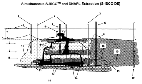
pronounced
groundwater flow. Wells for injecting oxidant and surfactant and/or cosolvent
can be placed
within the region of greatest contamination and upgradient of the region of
greatest
contamination, e.g., enhanced S-ISCO injection wells 2. The ratio of the
injection flow rate
of oxidant to that of surfactant and/or cosolvent can be adjusted, so that
solubilization
dominates, that is, more contaminant is mobilized than is oxidized. This
differs from a
standard S-ISCO approach, in which the ratio of the injection flow rate of
oxidant to
surfactant and/or cosolvent is set so that essentially all mobilized
contaminant is oxidized. In
the remediation design illustrated by Figure 1, it can be appropriate for more
contaminant to
be mobilized upgradient of and within the region of greatest contamination,
because the
mobilized contaminant is later removed further downgradient, as now described.
An
extraction well 3 located downgradient of the region of greatest contamination
can serve to
remove some, possibly the majority, of the mobilized contaminant.
[0097] An oxidation zone can be established by injecting oxidant through an
oxidant
injection well 6 located downgradient of the extraction well 3. In applying
ISCO, only
oxidant (with any carrier fluid, such as water) is injected through the
oxidant injection well 6.
The injected oxidant serves to destroy contaminant that migrates past the
extraction well.
Depending on the identity and concentration of the contaminant and the
oxidant, the
contaminant can be destroyed within a short distance of the oxidant injection
well 6. Or the
oxidant can travel downgradient with the contaminant, destroying the
contaminant in a
-18-
CA 02700766 2010-03-25
WO 2009/042224
PCT/US2008/011229
chemical oxidation zone 10 extending downgradient from the oxidant injection
well 6. In
either case, the contaminant is destroyed before it migrates too far
downgradient from the
region of greatest contamination, so that the contamination does not spread.
[0098] In applying S-ISCO, surfactant and/or cosolvent can be injected
along with
oxidant through the oxidant injection well 6. The injection of surfactant
and/or cosolvent
may be useful to maintain migrating contaminant in a solubilized or emulsified
state and
thereby promote the reaction of contaminant with oxidant. For example, the
surfactant ancUor
cosolvent injected upgradient in wells 2 may be degraded by the oxidant
present, so that a
supplemental injection of surfactant and/or cosolvent at oxidant injection
well 6 is
advantageous. However, the ratio of the flow rate of oxidant to the flow rate
of surfactant
and/or cosolvent injected at oxidant injection well 6 can be selected, so that
the rate of
oxidation dominates over the rate of mobilization in the chemical oxidation
zone
downgradient of the oxidant injection well 6. In this way, the contaminant is
destroyed in the
chemical oxidation zone and the injected surfactant and/or cosolvent is
destroyed in the
chemical oxidation zone, so that contaminant and excess surfactant and/or
cosolvent does not
spread to pollute the environment.
[0099] In other words, by using the approach of extraction in conjunction
with ISCO
or S-ISCO, a local rate of solubilization and/or emulsification of a
contaminant, such as
LNAPL and/or DNAPL, can greatly exceed the local rate of chemical oxidation,
provided
that the excess LNAPL and DNAPL solubilized and/or emulsified is captured and
removed
from the subsurface by extraction and that cross- and/or downgradient zones of
chemical
oxidation, e.g., oxidation zones, have been created in the subsurface to
ensure complete
oxidation of any solubilized chemicals not extracted.
[00100] The overall rate of oxidation can be controlled by controlling the
concentration of oxidant in the subsurface. For example, if a greater mass of
oxidant is
introduced into a given volume of subsurface, then the concentration of
oxidant in that
volume will be greater and the rate of oxidation will be faster. On the other
hand, if a lesser
mass of oxidant is introduced into a given volume of subsurface, then the
concentration of
oxidant in that volume will be lesser and the rate of oxidation will be
slower. The overall
oxidation rate can be controlled by selection of the specific oxidant used, as
well as the
concentration of the oxidant.
Selection of a Remediation Configuration
-19-
CA 02700766 2010-03-25
WO 2009/042224 PCT/t
S2008/011229
[00101] Consideration of factors such as the nature of the contaminant,
distribution of
the contaminant, geology, and hydrogeology, e.g., groundwater flow, of a site
to be
remediated can indicate the most appropriate configuration of an oxidant
injection well(s),
surfactant injection well(s), and/or extraction well(s). Selection
of an appropriate
configuration will prevent the spread of contaminant beyond a user-selected
remediation zone
in the subsurface. For example, if the oxidant zone or a combination of the
oxidant zone and
a geological feature, such as a stratum impermeable to the identified
contaminant that
completely separates the remediation zone from the rest of the subsurface,
i.e., the oxidation
zone encloses the extraction zone in the subsurface, the oxidation zone can
prevent the spread
of the targeted contaminant beyond the remediation zone. Alternatively, if the
groundwater
flow is such that essentially all the contaminant flows in one direction away
from the
contaminated site, then an oxidation zone can be established that intercepts
the flowing
groundwater and contaminant downstream of the contaminated site, and thereby
prevent the
spread of contaminant beyond a remediation zone established by the groundwater
flow and
the oxidation zone. Alternatively, the geology and hydrogeology surrounding a
contaminated
site may be such that contaminant does not migrate in one direction, but is
still limited to
migrate in certain directions without migrating in other directions. Such a
more complex
pattern of contaminant migration can be considered by a user in selecting a
remediation zone
and a configuration of extraction well(s), oxidant injection well(s), and
surfactant injection
well(s), so that contaminant does not migrate beyond the remediation zone,
while realizing
savings by not placing extraction, oxidant injection, and/or surfactant
injection well(s) in
areas through which the contaminant will not migrate. For example, oxidant
zone(s) can be
established to intersect all streamlines on which contaminant is present that
originated from
the contaminated site.
[00102] A user's selection of a remediation zone and configuration for
remediation will
be governed by a number of factors, that may include distribution of
contaminant, nature of
the contaminant (e.g., solubility in water), geology, hydrogeology, cost of
well drilling, cost
of chemicals such as oxidants and/or surfactants, intended future use of the
contaminated site
once remediated, property rights, state and federal environmental regulations,
and potential
liability if the contaminant spreads beyond property controlled by the
individual or
organization responsible for the cleanup (e.g., possibly greater if a
residential area surrounds
the contaminated site than if an industrial area surrounds the contaminated
site). In certain
cases, a user may find it necessary to reduce any further spread of
contaminant to a minimum,
-20-
CA 02700766 2010-03-25
WO 2009/042224 PCT/US2008/011229
and thus select a small remediation zone around the contaminated site and
completely
surround the site with an oxidant zone to prevent the spread of contaminant
beyond the
remediation zone. In other cases, a user may find it acceptable to allow some
further spread
of the contaminant if doing so will reduce the expense of remediation. For
example, if the
groundwater flow is such that streamlines passing through the contaminated
site converge at
a point downgradient of the contaminated site, it may be cost effective and
environmentally
acceptable to provide an oxidant zone at the point where the streamlines
converge.
[00103] In all
remediation approaches using extraction wells in conjunction with ISCO
or S-ISCO, monitoring wells can be used. For example, monitoring wells can be
used to
identify the extent of an oxidation zone created by injection of oxidant into
the subsurface.
For example, as illustrated in Figure 1, a monitoring well 12 can be located
within or
downgradient of a chemical oxidation zone extending downgradient from an
oxidant
injection well 6. The monitoring well 12 can be used to verify whether the
concentration of
contaminant has been reduced to an acceptable level and whether the
concentrations of
injected chemicals such as oxidant, surfactant, and/or cosolvent are at or
below acceptable
levels. Monitoring
wells can also be used, for example, to determine the flow of
groundwater, for example, by injecting tracer chemicals, and to determine
progress in
remediating contamination at the site.
[00104] For
example, confirmation that a zone of either ISCO or S-ISCO exists in the
subsurface can be made by monitoring physical and/or chemical characteristics
of soil and
groundwater in and around the subsurface zone where the solubilized or
emulsified LNAPLs
or DNAPLs are to be extracted. Physical characteristics to be monitored can
include pH,
temperature, specific conductance or electrolytic conductivity, turbidity,
dissolved oxygen,
surface tension (or interfacial tension), particle size distribution of
emulsions, density, and
viscosity. Chemical characteristics to be monitored can include, for example,
oxidation
reduction potential, presence or concentration of inorganic compounds or ions,
such as
sodium, potassium, ammonium, chloride, persulfate, sulfate, permanganate,
manganese,
radical scavenging species, inorganic carbon species, nitrate, nitrite,
phosphorous species,
activators, antioxidants, radical scavengers, stabilizers, metal species, and
iron species.
Organic chemical compound characteristics to be monitored can include, for
example,
surfactants, cosolvents, priority pollutants, organic carbon species, total
petroleum
hydrocarbon species, LNAPL and DNAPL chemical constituents, chelates,
activators,
antioxidants, radical scavengers, and stabilizers. Subsurface monitoring can
be used to
-21-
CA 02700766 2010-03-25
WO 2009/042224
PCT/US2008/011229
confirm that a zone of chemical oxidation, e.g., an oxidation zone, exists in
the subsurface in
the intended or actual remediation zone, such as in localized area(s) for
extraction, as well as
cross- and down-gradient of the localized extraction zone. For example, after
such a zone of
chemical oxidation is confirmed, extraction of contaminant and/or injection of
concentrations
of surfactants and/or cosolvents for solubilization and/or emulsification of
the LNAPL or
DNAPL can commence. The existence of a confirmed zone(s) of chemical oxidation
can
ensure that any solubilized or emulsified LNAPLs and/or DNAPLs not captured by
extraction
are treated, i.e., destroyed, in the chemical oxidation zone, e.g., at the
oxidation zone.
[00105] When surfactants and/or cosolvents are injected into the subsurface
to promote
the extraction and/or oxidation of contaminants, such as LNAPLs and/or DNAPLs,
the
surfactants and/or cosolvents can be injected in a range of low
concentrations, so that above
ground recycling of surfactants and/or cosolvents extracted is not required.
For example,
such a low range of surfactant and/or cosolvent concentration can range from
about 0.05
weight percent (wt%) to about 1 wt%. However, at certain contaminated sites,
for example,
certain sites with high concentrations of LNAPLs and/or DNAPLs, pooled DNAPLs,
or
LNAPLs floating on the water table, increasing the concentration of injected
surfactants
and/or cosolvents up to about 5% may be used to more cost-effectively extract
the
contaminant than if the surfactants and/or cosolvents were injected at lower
concentration.
For example, any extracted surfactants and/or cosolvents may be treated or
recycled above
ground.
[00106] ISCO or S-ISCO can be combined with a traditional SEAR method using
a
water in oil system, for example, a Winsor type 2 system, to remediate a
contaminated site.
For example, where NAPL mobilization and extraction is desired, with or
without above
ground treatment and recycling of injected surfactants and/or cosolvents, ISCO
or S-ISCO
can be used cross- and/or down-gradient from the SEAR treatment zone to ensure
that
mobilized NAPLs that are not extracted and/or surfactant and/or cosolvent
mixtures are
destroyed by chemical oxidants. This enables a safer application of SEAR, with
a reduction
of potential environmental and health risks associated with using SEAR alone.
Such an
application of ISCO or S-ISCO in conjunction with SEAR can involve the
installation of
ISCO or S-ISCO injections immediately down-gradient from the SEAR application.
Alternatively, such an application of ISCO or 5-ISCO in conjunction with SEAR
can involve
injections of ISCO or SISCO chemicals to establish an oxidation zone
downgradient from the
SEAR application zone. The specific chemical oxidants, surfactants, and/or
cosolvents used
-22-
CA 02700766 2010-03-25
WO 2009/042224
PCT/US2008/011229
to destroy any mobilized contaminants, such as LNAPLs and/or DNAPLs, and/or
surfactants
and/or cosolvents associated with the SEAR process that are not recovered by
extraction can
be selected through prior laboratory experimentation. For example, surfactants
and/or
cosolvents can be selected to be effective at mobilizing the target
contaminant(s). Surfactants
and/or cosolvents can be selected to be environmentally harmless and/or
biodegradable.
Oxidants can be selected to destroy the target contaminant(s) and other SEAR
chemicals
used, such as surfactants and/or cosolvents, and harmful degradation products
of
contaminants, surfactants and/or cosolvents. Once the SEAR process is
completed, ISCO or
S-ISCO treatment can be applied within the zone of former SEAR treatment to
ensure that
contaminants are eliminated or reduced to an acceptable level.
[00107] ISCO or S-ISCO can be applied at sites where SEAR has been used in
the
past, and contamination still remains as a result of incomplete treatment
and/or undesirable
by-products from the SEAR process remain.
Control Over Surfactant Oxidant Systems for Remediation
[00108] An amount of surfactant or surfactant-cosolvent mixture can be
introduced
into a subsurface, for example, rock, soil, or groundwater, including a
contaminant, for
example, a NAPL, to form a Winsor Type I system. In order to form a Winsor
Type I
system, the amount of surfactant or surfactant-cosolvent mixture added is
controlled and
restricted; that is, not so much of a surfactant or surfactant-cosolvent
mixture is added to
induce the formation of a Winsor Type II system, but enough to result in
increased
solubilization of the NAPL above the aqueous critical micelle concentration.
Thus, the
formation of a Winsor Type II system and the mobilization of contaminant, for
example,
NAPL, associated with a Winsor Type II system, is avoided or minimized. By
avoiding or
minimizing the mobilization of contaminant, the problem of contaminant
migrating to areas
not being treated can be avoided. For example, sufficient surfactant can be
injected into a
region that serves as an oxidation zone to increase the amount of a NAPL
contaminant in the
aqueous phase, for the purpose of increasing the rate of oxidation of the
contaminant. At the
same time, the amount of surfactant injected can be kept sufficiently small so
that a Winsor
Type I, and not a Winsor Type II system is formed. By forming a Winsor Type I
system in
the oxidation zone, mobilization of contaminant, such as a NAPL, beyond the
oxidation zone
is minimized.
[00109] Contaminant in a subsurface can be locally mobilized in a
controlled manner;
-23-
CA 02700766 2010-03-25
WO 2009/042224
PCT/US2008/011229
then, the mobilized contaminant can be oxidized. For example, at a site
contaminated with
NAPLs, the NAPLs may accumulate in sufficient thicknesses that the relative
permeability to
water in the NAPL accumulation zone is very low and injected chemicals simply
pass over,
under or around the NAPL accumulation zone, leaving the area untreated. A
Winsor Type II
or Type III system can be locally formed, for example, near such a NAPL
accumulation zone
in the subsurface to mobilize the NAPLs to travel into subsurface zones where
they are more
available to and have greater contact with oxidant chemicals in the aqueous
phase. The
emulsion then can be broken, for example, with an oxidant or other emulsion
breaker, to
create, for example, a Winsor Type I system to make the NAPL more available to
react with
the oxidant solution. For example, a Winsor Type III system can mobilize a
contaminant
phase, for example, a NAPL phase, in the microemulsion. For example, when the
NAPL
content of soil in a subsurface is low, a Winsor Type III middle phase
microemulsion can be
formed to mobilize the NAPL into a bulk pore space and then oxidize the
emulsified NAPL
in the bulk pore space, for example, by chemical oxidation. For example,
surfactant can be
injected into the subsurface to form a Winsor Type II or Type III system in
the vicinity of the
extraction well. The Winsor Type II or Type III can effectively mobilize the
NAPL to
enhance its extraction by the well from the subsurface.
S-ISCO Orderin2 of Surfactant and Oxidant Injection
[00110] In
implementing S-1SCO, the surfactant or surfactant-cosolvent mixture can be
introduced sequentially or simultaneously (together) into a subsurface. For
example, the
surfactant or surfactant-cosolvent mixture can first be introduced, then the
oxidant and/or
other injectants can be introduced. Alternatively, the oxidant can first be
introduced, then the
surfactant or surfactant-cosolvent mixture can be introduced. Alternatively,
the oxidant and
the surfactant or surfactant-cosolvent mixture can be introduced
simultaneously.
Simultaneously can mean that the oxidant and the surfactant and/or cosolvent
are introduced
within 6 months of each other, within 2 months of each other, within 1 month
of each other,
within 1 week of each other, within 1 day of each other, within one hour of
each other, or
together, for example, as a mixture of oxidant with surfactant and/or
cosolvent. In each case,
the oxidant is present in sufficient amounts at the right time, together with
the surfactant, to
oxidize contaminants as they are solubilized or mobilized by surfactant or
cosolvent-
surfactant mixture.
-24-
CA 02700766 2010-03-25
WO 2009/042224 PCT/U
S2008/011229
Form of Injected Treatment Chemicals
[00111] The
introduced compositions, which can include oxidant, surfactant, activator,
cosolvent, and/or salts, can be introduced into the subsurface in the solid
phase. For example,
the location where the compositions are introduced can be selected so that
groundwater can
dissolve the introduced compositions and convey them to where the contaminant
is.
Alternatively, the introduced compositions such as oxidant, surfactant,
activator, cosolvent,
and salts can be introduced into the subsurface as an aqueous solution or
aqueous solutions.
Alternatively, some compositions can be introduced in the solid phase and some
can be
introduced in aqueous solution.
Physical Injection Parameters: Delivery of Treatment Chemicals to Contaminant
[00112] In an
embodiment of the invention, the contaminated zone to be treated can be
the subsurface. Alternatively, the contaminated zone to be treated can be
above ground, for
example, in treatment cells, tanks, windrows, or other above-ground treatment
configurations.
[00113] In an
embodiment of the invention, the introduced compositions may be
applied to the subsurface using injection wells, point injection systems, such
as auger, direct
push or other hydraulic or percussion methods, trenches, ditches, ancUor by
using manual or
automated methods. In an embodiment of the invention, the introduced
compositions may be
applied to the subsurface using emplaced fractures using hydraulic or sonic
methods or
directly into fractures and/or fracture networks that exist in bedrock.
[00114] An
embodiment of the invention involves the use of controlling the specific
gravity of the introduced compositions, consisting of oxidants, activating
solutions, salts,
surfactants, and/or surfactant-cosolvent mixtures. By controlling the specific
gravity of the
injected solutions, greater control of the vertical interval of the volume of
soil treated can be
achieved. Sites with high concentrations of NAPL or sorbed organic chemicals
in soils
generally require higher concentrations of oxidants than needed at sites with
lower
concentration of contaminants. Injecting
oxidant/activator/surfactant chemicals into the
subsurface at sites with a high demand for these injected chemicals can result
in solutions
with densities great enough to induce downward density driven flow caused by
gravitational
effects. Variation of the concentration of salts associated with either the
oxidant or externally
added salts affects the density, which affects the vertical interval of soil
contacted by the
injected liquids. Controlling the density of the injected liquids enables a
controlled and
deliberate treatment of contaminated intervals in the subsurface.
-25-
CA 02700766 2010-03-25
W. 0 2009/042224
PCT/US2008/011229
[00115] The injection flow rate is another parameter which can be
controlled to deliver
treatment chemicals, e.g., oxidant, activator, and surfactant, to where
chemicals of concern
(COCs) reside.
[00116] For example, if dense non-aqueous phase liquids (DNAPLs) are to be
targeted,
the density of the injected liquids can be selected to be from about as great
to greater than the
density of water. For example, the density of the injected liquids can be
selected to be in the
range of from about 1.0 gram/cm3 to about 1.5 gram/cm3.
[00117] For example, shallow contamination near the water table can be
effectively
targeted by using persulfate concentrations in the, say, 10 g/L (grams per
liter) to 15 g/L
range and moderately high injection flowrates, e.g., up to 30 gpm (gallons per
minute) per
injection location, dependent on the geometry of the injection trench or
wells. For
intermediate depth locations, persulfate concentrations up to, say, 25 g/L can
be used with,
e.g., up to 20 gpm per injection, dependent on the geometry of the injection
trench or wells.
For deeper DNAPL contamination, persulfate concentrations up to 100 g/L can be
used
dependent on the nature of the DNAPL distributions and concentrations.
Injection flowrates
for deep DNAPL applications can be up to, say, 20 gpm per well, if injected
above the lower
permeability layers and up to, say, 10 gpm per well, if injected in the lower
permeability unit.
Unlike permanganate, persulfate forms no significant solid phase precipitates.
[00118] In an embodiment of S-ISCO remediation, a formulation can be
introduced
into the subsurface above the water table, that is, into the unsaturated or
vadosc zone. The
introduced composition can include cosolvent, surfactant, or a
cosolvent/surfactant mixture,
can include an oxidant, and can optionally further include an activator. The
density of the
introduced composition can be adjusted to be less than that of water.
Introducing such a
composition into the subsurface above the water table can be used to control
the volatilization
of volatile inorganic and/or organic chemicals from the saturated zone into
the unsaturated
zone in order to prevent or minimize the risk of exposure of people to vapors
of these volatile
inorganic and/or organic chemicals.
Composition of Injected Materials: Surfactants, Cosolvents
[00119] Surfactant or surfactant-cosolvent mixtures to solubilize NAPL
components and
desorb contaminants of concern (COCs) from site soils or from NAPL in water
mixtures can be
screened for use in a combined surfactant-oxidant treatment. For
example, blends of
-26-
CA 02700766 2010-03-25
NN 0 2009/042224 PCT/US2008/011229
biodegradable citrus-based solvents (for example, d-limonene) and degradable
surfactants
derived from natural oils and products can be used.
[00120] For example, a composition of surfactant and cosolvent can include
at least one
citrus terpene and at least one surfactant. A citrus terpene may be, for
example, CAS No.
94266-47-4, citrus peels extract (citrus spp.), citrus extract, Curacao peel
extract (Citrus
aurantium L.), EINECS No. 304-454-3, FEMA No. 2318, or FEMA No. 2344. A
surfactant
may be a nonionic surfactant. For example, a surfactant may be an ethoxylated
castor oil, an
ethoxylated coconut fatty acid, or an amidified, ethoxylated coconut fatty
acid. An ethoxylated
castor oil can include, for example, a polyoxyethylene (20) castor oil, CAS
No. 61791-12-6,
PEG (polyethylene glycol)-10 castor oil, PEG-20 castor oil, PEG-3 castor oil,
PEG-40 castor
oil, PEG-50 castor oil, PEG-60 castor oil, POE (polyoxyethylene) (10) castor
oil, POE(20)
castor oil; POE (20) castor oil (ether, ester); POE(3) castor oil, POE(40)
castor oil, POE(50)
castor oil, POE(60) castor oil, or polyoxyethylene (20) castor oil (ether,
ester). An ethoxylated
coconut fatty acid can include, for example, CAS No. 39287-84-8, CAS No. 61791-
29-5, CAS
No 68921-12-0, CAS No. 8051-46-5, CAS No. 8051-92-1, ethoxylated coconut fatty
acid,
polyethylene glycol ester of coconut fatty acid, ethoxylated coconut oil acid,
polyethylene
glycol monoester of coconut oil fatty acid, ethoxylated coco fatty acid, PEG-
15 cocoate, PEG-5
cocoate, PEG-8 cocoate, polyethylene glycol (15) monococoate, polyethylene
glycol (5)
monococoate, polyethylene glycol 400 monococoate, polyethylene glycol
monococonut ester,
monococonate polyethylene glycol, monococonut oil fatty acid ester of
polyethylene glycol,
polyoxyethylene (15) monococoate, polyoxyethylene (5) monococoate, or
polyoxyethylene (8)
monococoate. An amidified, ethoxylated coconut fatty acid can include, for
example, CAS No.
61791-08-0, ethoxylated reaction products of coco fatty acids with
ethanolamine, PEG-11
cocamide, PEG-20 cocamide, PEG-3 cocamide, PEG-5 cocamide, PEG-6 cocamide, PEG-
7
cocamide, polyethylene glycol (11) coconut amide, polyethylene glycol (3)
coconut amide,
polyethylene glycol (5) coconut amide, polyethylene glycol (7) coconut amide,
polyethylene
glycol 1000 coconut amide, polyethylene glycol 300 coconut amide,
polyoxyethylene (11)
coconut amide, polyoxyethylene (20) coconut amide, polyoxyethylene (3) coconut
amide,
polyoxyethylene (5) coconut amide, polyoxyethylene (6) coconut amide, or
polyoxyethylene
(7) coconut amide.
[00121] Examples of cosolvents which preferentially partition into the NAPL
phase
include higher molecular weight miscible alcohols such as isopropyl and tert-
butyl alcohol.
Alcohols with a limited aqueous solubility such as butanol, pentanol, hexanol,
and heptanol
-27-
CA 02700766 2010-03-25
WO 2009/042224 PC Till S2008/011229
can be blended with the water miscible alcohols to improve the overall phase
behavior. Given
a sufficiently high initial cosolvent concentration in the aqueous phase (the
flooding fluid),
large amounts of cosolvent partition into the NAPL. As a result of this
partitioning, the
NAPL phase expands, and formerly discontinuous NAPL ganglia can become
continuous,
and hence mobile. This expanding NAPL phase behavior, along with large
interfacial tension
reductions, allows the NAPL phase to concentrate at the leading edge of the
cosolvent slug,
thereby increasing the mobility of the NAPL. Under certain conditions, a
highly efficient
piston-like displacement of the NAPL is possible. Because the cosolvent also
has the effect of
increasing the NAPL solubility in the aqueous phase, small fractions of the
NAPL which are
not mobilized by the above mechanism are dissolved by the cosolvent slug.
Activation of Oxidant
[00122] An activator can be, for example, a chemical molecule or compound,
or another
external agent or condition, such as heat, temperature, or pH, that increases
the rate of or
hastens a chemical reaction. The activator may or may not be transformed
during the chemical
reaction that it hastens. Examples of activators which are chemical compounds
include a metal,
a transition metal, a chelated metal, a complexed metal, a metallorganic
complex, and hydrogen
peroxide. Examples of activators which are other external agents or conditions
include heat,
temperature, and high pH. Preferred activators include Fe(II), Fe(III), Fe(II)-
EDTA, Fe(III)-
EDIA, Fe(II)-EDDS, Fe(III)-EDDS, Fe(II)-citric acid, Fe(III)-citric acid,
hydrogen peroxide,
high pH, and heat.
[00123] Non-thermal ISCO using persulfate requires activation by ferrous
ions, Hoag,
G. et al. (2000)(ref. 12) but preferentially chelated metals Brown, R. et al.
(2002), Hoag, G. and
Mao, F. (2004), Liang, C. et al. (2004) (ref. 13). Chelated iron has been
demonstrated to
prolong the activation of persulfate enabling activation to take place at
substantial distances
from injection wells.
[00124] Several practical sources of Fe(II) or Fe(III) can be considered
for activation of
persulfate. Iron present in the soil minerals that can be leached by injection
of a free-chelate (a
che late not complexed with iron, but usually Na+ and H+) can be a source.
Injection of soluble
iron as part of a chelate complex, such as Fe(II)-EDTA, Fe(II)-NTA or Fe(II)-
Citric Acid (other
Fe-chelates are available) can be a source. Indigenous dissolved iron
resulting from reducing
conditions present in the subsurface (common at many MGP sites) can be a
source. For the
Pilot Test, discussed as an example below, Fe(II)-EDTA was used.
-28-
CA 02700766 2010-03-25
W 0 2009/042224
PCT/US2008/011229
[00125] An example
of an oxidant is persulfate, e.g., sodium persulfate, of an activator is
Fe(II)-EDTA, of a surfactant is Alfoterra 53, and of a cosolvent-surfactant
mixture is a mixture
of d-limonene and biodegradable surfactants, for example, Citrus Burst 3.
Citrus Burst 3
includes a surfactant blend of ethoxylated monoethanolamides of fatty acids of
coconut oil and
polyoxyethylene castor oil and d-limonene.
[00126] An
embodiment of the invention is the simultaneous or sequential use of the
oxidant persulfate, and an activator to raise the of the
groundwater to above 10.5 by the
addition of CaO, Ca(OH)2, NaOH, or KOH, an example of a cosolvent-surfactant
is Citrus
Burst 3.
Testing for Remediation Configuration Development
[00127] Several
surfactants, cosolvents, or surfactant-cosolvent mixtures for
dissolution and/or desorption of a given NAPL or sorbed organic chemical (or
mixture of
chemicals) can be screened to develop a customized and optimal surfactant,
cosolvent, or
surfactant-cosolvent mixture to dissolve either some or all of the NAPLs or
sorbed chemicals.
In order to dissolve some or all of the NAPLs or sorbed chemicals, a
surfactant or mixture of
surfactants alone, a cosolvent or mixture of cosolvents alone, or a mixture of
surfactants and
cosolvents can be used. For example, certain volatile constituents in the
NAPLs may pose a
health or ecological risk at a particular site, that is, be contaminants of
concern (COCs), but
the NAPLs may contain many other compounds that do not result in risks. This
invention
presents methods to screen different types of surfactants, cosolvents, and
cosolvent-surfactant
mixtures to obtain an optimal dissolution or desorption of the contaminants of
concern,
resulting in the oxidation predominantly only of those compounds that need to
be treated to
reduce risk or reach remediation goals for a given site.
[00128] The
surfactants and/or cosolvents can be chosen to selectively solubilize
contaminants, for example, certain NAPLs, that pose a risk to public health
and/or the
environment, without solubilizing other compounds. Similarly, by choosing an
oxidant that
is capable of only oxidizing certain classes of compounds, one can select an
oxidant that only
treats selected solubilized target compounds. For example, persulfate that is
not activated
effectively treats volatile organic compounds (VOCs) but does not effectively
treat other
compounds such as certain hydrocarbons including some PAHs. Additionally,
permanganate
can effectively treat chloroethene compounds, but does not effectively treat
certain
chloroethane compounds. The method of screening surfactants and cosolvents to
determine
-29-
CA 02700766 2010-03-25
WO 2009/042224
PCT/US2008/011229
which compounds in the NAPL, solid, or sorbed phases can be dissolved or
emulsified in an
oil in water emulsion or soluble micelle, then selecting an oxidant that is
also selective in
tenms of what compounds are treated creates a system not previously discovered
that is a
powerful tool to cost-effectively treat sites, where simple injection of a
surfactant or
surfactant-cosolvent mixture alone or oxidant alone would be slower,
ineffective or not cost-
effective. Thus, the new approach presented in this application enables more
efficient,
effective, and optimal treatment of contaminated soils, for example, soils
contaminated with
NAPLs and/or other organic chemicals, for example, benzene, toluene, ethyl
benzene, xylene,
and polyaromatic hydrocarbons.
[00129] The oxidant
and surfactant or surfactant-cosolvent mixture can be selected so
that the oxidant does not substantially react with the surfactant or
cosolvent. Alternatively,
the oxidant and surfactant or surfactant-cosolvent mixture can be selected so
that the
surfactant can function to solubilize contaminant, for example, NAPL, even if
the oxidant
reacts with the surfactant or cosolvent.
Alternatively, the oxidant and surfactant or
surfactant-cosolvent mixture can be selected so that the oxidant reacts with
the surfactant so
as to promote the destruction of contaminant, for example, NAPL. For example,
the oxidant
may react with the surfactant to alter the chemistry of the surfactant, so
that the altered
surfactant selectively solubilizes certain contaminants. For example, an
oxidant can be
chosen that controls the interfacial tension of the resultant soil NAPL/water
interface and
promotes selective solubilization of surface contaminants.
[00130] Field
applications of S-1SCO technologies at sites with organic contaminants
in either or both of the LNAPL and DNAPL phases or with sorbed phases are
dependent on
several factors for successful achievement of removal of the NAPL or sorbed
phases with this
new method and process. These factors can include the following:
1) Effective delivery of injected oxidants, activating solutions, and
surfactants or surfactant-
cosolvent mixture into the subsurface.
2) Travel of oxidant, activator, and surfactant solutions to the desired
treatment interval in the
soil.
3) Selection of surfactants or cosolvent-surfactant mixtures and oxidants to
ensure coelution
of the surfactants or cosolvent-surfactant mixtures and oxidants enabling
travel of the injected
species to the desired treatment interval in the soil.
4) Desorption and apparent solubilization of residual NAPL phases into the
aqueous phase
for destruction by the oxidant and radical species.
-30-
CA 02700766 2010-03-25
WO 2009/042224
ITT/US2008/011229
5) Reactions of oxidant and radical species with target mobilized contaminants
of concern
(COCs).
6) Production of by-products from oxidation and any other injected solutions,
including
organic or metal species that are below concentrations of regulatory
thresholds.
7) Oxidation or natural or enhanced biodegradation of the surfactant or
surfactant-cosolvent
mixture.
8) Adequate monitoring of COCs, injected oxidant and activator solutions,
essential
geochemical parameters and any other environmental media potentially affected
by the
treatment.
[00131] The method of
using this new S-ISCO technology may involve separate
screening and testing of the surfactant and cosolvents, separate testing of
optimal oxidant (to
meet site needs) and then testing the technologies together. This work can be
done in the
laboratory environment or in a combination of the laboratory environment and
during field
testing. This method can involve following steps.
[00132] Collection of
site soils and groundwater representative of the highly
contaminated soils targeted for S-ISCO treatment. In some cases it may be
desirable to add
NAPL from the site to the test soils. (One objective of this step is to
provide information
concerning potential remedies for a range of soil contaminant conditions,
including
conditions approaching the most contaminated on the site.)
[00133] Aqueous phase
screening can be used for the selection of appropriate oxidants
with and without activators or cosolvents for the destruction of selected COCs
in collected
groundwater from the site.
[00134] A catalyst is a
substance that increases or hastens the rate of a chemical
reaction, but which is not physically or chemically changed during the
reaction. For example, a
preferred oxidant to use is persulfate, e.g., sodium persulfate. Attributed to
its relatively high
stability under normal subsurface conditions, persulfate more effectively
travels through the
subsurface into the target contaminant zone, in comparison to hydrogen
peroxide associated
with Fenton's or Modified Fenton's Chemistry. Other
oxidants include ozone and
perrnanganate, percarbonates, hydrogen peroxide, and various hydrogen peroxide
or Fenton's
Reagent mixtures. A control system should be run to compare the treatment
conditions to those
with no treatment. Additionally, tests of the stability of the surfactant or
surfactant-cosolvent
mixture can be necessary to ensure that the oxidant does not immediately, or
too quickly,
-31-
CA 02700766 2010-03-25
WO 2009/042224 PC1/11S2008/011229
oxidize the surfactant or cosolvent-surfactant mixture rendering it useless
for subsequent
dissolution.
[00135] Soil slurry tests can be run on selected combinations of surfactant
or surfactant-
cosolvent mixtures to determine the solubilization of specific COCs relative
to site cleanup
criteria. Additionally, soil slurry tests can be run to screen and determine
optimal dosing of
chemical oxidants for both dosing requirements and COCs treated. The
technology of
combining enhanced solubilization by surfactants or surfactant-cosolvent
mixtures with
chemical oxidation is a more aggressive approach to desorb residual tars,
oils, and other
NAPI.s from the soils and simultaneously oxidize the desorbed COCs with the
chosen chemical
oxidant. A soil slurry control system can be run to compare the treatment
conditions with no
treatment.
[00136] Soil column tests can be run to closely simulate treatment
performance and
COC destruction using soil cores obtained from the most highly contaminated
soils associated
with the proposed surface enhanced in situ chemical oxidation (S-ISCOTNI)
treatment areas of a
site. Results from soil column tests can be used to identify the treatment
conditions and
concentrations of chemicals to be evaluated. The soil column tests can consist
of using one
oxidant alone or a mixture of oxidants simultaneously with a surfactant or a
mixture of
surfactants or a cosolvent-surfactant mixture; various configurations or
concentrations of
oxidants or mixtures of oxidants used alone or simultaneously with a
surfactant or a cosolvent-
surfactant mixture can be selected for study based on soil slurry tests.
Different activation
methods can additionally be tested using soil column testing. By monitoring
surfactant
concentrations and/or interfacial tension in the effluent of the soil columns,
the reactivity of the
surfactant and cosolvents with the oxidants can be determined to determine
compatibility of
oxidants with surfactants and cosolvents. Monitoring of COC concentrations in
the effluent of
the column can also determine the ability of the oxidant to destroy the
cosolvent-surfactant or
surfactant micelles or emulsions and react with the COCs.
[00137] Data analysis of processes monitored, as described above, enables
design
criteria for the development of pilot- and full-scale implementation of the S-
ISCO technology
to be implemented in the field. Design parameters include moles of oxidant
used in the tests
per mole of COCs destroyed, moles of oxidant used per mass of soil treated,
moles of
surfactant utilized per mole of COC solubilized, moles of surfactant or of
cosolvent-surfactant
mixture destroyed per unit contact time in the batch or column test, rates of
COC destruction,
rates of oxidant utilization, and loading rates of chemicals.
-32-
CA 02700766 2010-03-25
0 2009/042224 PCT/1JS2008/011229
Methods for Determining Contaminant Remediation Protocols
[00138] A method for determining a contaminant remediation protocol, for
example, of
a protocol for remediating soil in a subsurface contaminated with NAPL or
other organic
chemicals, can include the following steps. Site soil samples can be collected
under zero
headspace conditions (e.g., if volatile chemicals are present); for example,
samples
representative of the most highly contaminated soils can be collected. The
samples can be
homogenized for further analysis. A target contaminant or target contaminants
in the soil can
be identified. The demand of a sample of oxidant per unit soil mass can be
determined; for
example, the demand of a soil sample for a persulfate oxidant, such as sodium
persulfate, can
be determined. An oxidant is, for example, a chemical or agent that removes
electrons from a
compound or element, increases the valence state of an element, or takes away
hydrogen by
the addition of oxygen. A suitable oxidant and/or a suitable mixture of an
oxidant and an
activator for oxidizing the target contaminant can be selected. Suitable
surfactants, mixtures
of surfactants, and/or mixtures of surfactants, cosolvents, and/or solvents
capable of
solubilizing and/or desorbing the target contaminant or contaminants can be
identified; for
example, suitable biodegradable surfactants can be tested. Suitable solvents
capable of
solabilizing and/or desorbing the target contaminant or contaminants can be
identified; for
example, suitable biodegradable solvents such as d-limonene can be tested.
Various
concentrations of cosolvent-surfactant mixtures or surfactants alone can be
added to water or
groundwater from a site along with controlled quantities of NAPLs.
Relationships of the
extent of dissolution of the NAPL compounds with the varying concentrations of
the
cosolvent-surfactant mixtures or surfactants can be established by measuring
the
concentrations of the NAPL compounds that enter the aqueous phase.
Relationships between
the interfacial tension and solubilized NAPL compounds and their molecular
properties, such
as the octanol-water partition coefficient (Kow) can also be established that
enable optimal
design of the dissolution portion of the S-ISCO process. Various
concentrations of
cosolvent-surfactant mixtures or surfactants alone can be added to water or
groundwater from
a site along with controlled quantities of contaminated soils from the site.
Relationships of
the extent of solubilization of the sorbed COC compounds with the varying
concentrations of
the cosolvent-surfactant mixtures or surfactants can be established by
measuring the
concentrations of the sorbed COCs that enter the aqueous phase. Relationships
between the
-33-
CA 02700766 2010-03-25
WO 2009/042224
PCT/1JS2008/011229
interfacial tension and desorbed and solubilized compounds and their molecular
properties,
such as the octanol water partition coefficient (K), can also be established
that enable
optimal design of the dissolution portion of the S-1SCO process. The
simultaneous use of
oxidants and surfactants or cosolvent-surfactant mixtures in decontaminating
soil can be
tested. For example, the effect of the oxidant on the solubilization
characteristics of the
surfactant can be evaluated, to ensure that the oxidant and surfactant can
function together to
solubilize and oxidize the contaminant. The quantity of surfactant for
injection into the
subsurface can be chosen to form a Winsor I system or a microemulsion.
[00139] For
example, the type and quantity of surfactants and optionally of cosolvent
required to solubilize the target contaminant can be determined in a batch
experiment.
[00140] It can be
important that the oxidant not react with the surfactant so fast that the
surfactant is consumed before the surfactant can solubilize the contaminant.
On the other
hand, the surfactant should not reside in the subsurface indefinitely, to
avoid being a
contaminant itself This degradation can be caused by living organisms, such as
bacterial,
through a biodegradation process. On the other hand, the surfactant can be
selected to slowly
react with the oxidant, so that the oxidant survives sufficiently long to
solubilize the
contaminant for the purpose of enhancing its oxidation, but once the
contaminant has been
oxidized, the surfactant itself is oxidized by the remaining oxidant.
[00141] At the
oxidation zone, it may be acceptable for the oxidant to rapidly degrade
the surfactant. If the surfactant is degraded, oxidation of the contaminant
may be slowed,
because only a small amount of contaminant is in the aqueous phase. However,
at the same
time, the contaminant may be effectively immobilized. This immobilization can
prevent the
contaminant from passing through the oxidation zone. Thus, even if the oxidant
rapidly
degrades the surfactant, the objective of preventing the contaminant from
spreading beyond
the oxidation zone may still be achieved.
[00142]
Experimentation on the effects of various oxidants, combinations of oxidants,
and activators on the stability and activity of cosolvent-surfactant mixtures
and surfactants
can be readily conducted to provide information to optimize S-ISCO treatment
conditions.
Testing of the sorption or reaction of the surfactant or surfactant-cosolvent
mixture can be
conducted to determine the transport and fate properties of the surfactant or
surfactant-
cosolvent mixture in soils, rock and groundwater. Testing is conducted in
batch aqueous or
soil slurry tests in which individual cosolvent-surfactant mixtures or
surfactants at specified
initial concentrations are mixed together with individual oxidants or mixtures
of oxidants and
-34-
CA 02700766 2010-03-25
WO 2009/042224
PCTMS2008/011229
activators. The duration of the tests is a minimum of 10 days and as long as
120 days,
dependent on the stability of the oxidant-surfactant system needed for a
particular
application.
Selection of Surfactant System
[00143] Development of a surfactant system for use in S-ISCO remediation
can
include preparing a series of surfactants or surfactant-cosolvent mixtures.
One characteristic
of a surfactant-cosolvent mixture is the ratio of the number of ethylene oxide
groups to
propylene oxide groups (E0/P0 ratio) in the backbones of the constituent
molecules. The
surfactant-cosolvent mixtures in the series can have a range of EO/PO ratios.
The EO/PO
ratio of a mixture can be determined from knowledge of the EO/PO ratios of the
constituent
molecules and the molar fraction of each type of constituent molecule in the
mixture. The
hydrophobicity of the surfactant-cosolvent mixture can be tailored by
adjusting the EO/PO
ratio through varying the types of surfactant and cosolvent molecules in the
mixture, or by
varying the concentrations of the types of surfactant and cosolvent molecules
in the mixture.
[00144] The hydrophilic-lipophilic balance (HLB) is a characteristic of a
surfactant.
An HLB of less than 10 indicates a surfactant in which the oleophilic
(hydrophobic) property
is stronger than the hydrophilic property of the surfactant. An HLB of greater
than 10
indicates a surfactant in which the hydrophilic property is stronger than the
oleophilic
(hydrophobic) property of the surfactant.
[00145] A characteristic of organic chemicals is a characteristic known as
the octanol-
water partition coefficient (Kow). The 1(0,, can be determined, for example,
in a batch test in
which the concentrations of an organic molecular species (such as COCs) in the
octanol
phase and the concentration of the molecular species in the water phase are
measured. The
partitioning of the organic species between the octanol and water phases is a
property of
organic chemicals reported in the literature from both experimental
measurements and
theoretical approximations. Relationships between the octanol-water partition
coefficients of
particular COCs and their solubilization in cosolvent-surfactant or surfactant
systems is
important in the evaluation and optimal design of the S-ISCO process.
[00146] The surfactant mixtures in the series can have various HLB value
distributions. For example, a surfactant mixture can have a narrow HLB value
distribution
and can have a either high average HLB values, for example 12 to 15, or low
average HLB
values 10 to 12. Alternatively, a surfactant-cosolvent mixture can have a
broad HLB value
-35-
CA 02700766 2010-03-25
WO 2009/042224
PCT/US2008/011229
distribution with HLB values variable depending on the particular NAPL or
sorbed chemical
species requiring treatment.
[00147] The surfactant mixtures in the series can have various molecular
weight
distributions. For example, a surfactant mixture can have a narrow molecular
weight
distribution and can have a low or a high average molecular weight.
Alternatively, a
surractant-cosolvent mixture can have a broad molecular weight distribution.
[00148] A study included preparation of a series of surfactant-cosolvent
mixtures in
which the EO/PO ratio and average molecular weight were varied for different
COCs (Diallo
et al. (1994)). Batch testing was performed on the ability of a surfactant-
cosolvent mixture to
solubilize a hydrocarbon, e.g., a contaminant targeted for remediation. It was
observed that
as the HLB of the surfactant increased that the solubilization of COC
increased through a
maximum, then decreased as the HLB further increased.
[00149] Thus for a given molecular contaminant species there is an optimal
value of
HLB for the surfactant to solubilize it. For a distribution of contaminant
molecules there is
an optimal distribution of HLB values. Thus, an aspect of the method presented
here is
determining an optimal surfactant or cosolvent-surfactant mixture, based on
the HLB for
which solubilization is maximized for subsequent or simultaneous oxidation of
the
solubilized species. An advantage of this approach is that, should
circumstances require, e.g.,
a change in government regulations or cost of a particular surfactant, a
different surfactant
having a similar HLB can be substituted for a surfactant in a treatment
composition.
[00150] The ability to tailor the EO/PO ratio and the molecular weight
distribution of
molecules in the surfactant-cosolvent mixture and thereby adjust the HLB of
the surfactant
allows the surfactant-cosolvent mixture to be optimized for a targeted
contaminant and for
sequential or simultaneous oxidation.
[00151] The transport properties of the surfaetant or surfactant-cosolvent
mixture in
the soil of the site to be remediated can also be tested, for example, in soil-
column tests.
Characteristics of the soil, for example, surface chemistry, clay minerology,
and/or pH may
affect the transport properties of the surfactant or surfactant-cosolvent
mixture through the
soil. The results of testing of transport properties, or observations of
transport properties in
the field of the surfactant or surfactant-cosolvent mixture may indicate
further tailoring of the
hydrophilic characteristics of the surfactant. It may be indicated to trade-
off some of the
desired solubilization characteristics for required transport characteristics
in developing a
surfactant or surfactant-cosolvent mixture that is optimal for the site to be
remediated.
-36-
CA 02700766 2010-03-25
WO 2009/042224
PCPUS2008/011229
Testine of Compositions for Injection
[00152] Testing of oxidants, surfactants, activators, cosolvents and/or
solvents can be
conducted with the contaminant in the non-aqueous phase and/or sorbed phase in
aqueous
solution, or with the contaminant in a soil slurry or soil column. A soil
slurry or soil column
can use a standard soil or actual soil from a contaminated site. An actual
soil can be
homogenized for use in a soil slurry or soil column. Alternatively, an intact
soil core
obtained from a contaminated site can be used in closely simulating the effect
of introduction
of oxidant, surfactant, and/or solvent for treatment.
[00153] Testing of oxidants, surfactants, activators, cosolvents, and/or
solvents can be
conducted with the contaminant in a batch experiment, with or without soil.
[00154] The range of quantity of surfactant that can form a Winsor Type I,
II, or III
system or a microemulsion in the subsurface can be identified.
[00155] Various techniques can be used in conjunction with surfactant
enhanced in situ
chemical oxidation (S-ISCO) treatment, for example, use of macro-molecules or
cyclodextrins, steam injection, sparging, venting, and in-well aeration.
[00156] An aspect of the control that can be achieved by use of an
embodiment of the
invention for site remediation is direction of antioxidant to a target region
of contaminant.
The density of the injected solution can be modified, so that the oxidant
reaches and remains
at the level in the subsurface of the target region of contaminant. Additional
factors such as
subsurface porosity and groundwater flow can be considered to locate wells for
injecting
solution containing oxidant, so that oxidant flows to the target region of
contaminant.
[00157] In an embodiment, the consumption of oxidant can be further
controlled by
including an antioxidant in the injected solution. For example, an antioxidant
can be used to
delay the reaction of an oxidant. Such control may prove important when, for
example, the
injected oxidant must flow through a region of organic matter which is not a
contaminant and
with which the oxidant should not react. Avoiding oxidizing this non-
contaminant organic
matter may be important to maximize the efficiency of use of the oxidant to
eliminate the
contaminant. That is, if the oxidant does not react with non-contaminant
organic matter, then
more oxidant remains for reaction with the contaminant. Furthermore, avoiding
oxidizing
non-contaminant organic matter may be important in its own right. For example,
topsoil or
compost may be desirable organic matter in or on soil that should be retained.
The anti-
-37-
CA 02700766 2010-03-25
\ 2009/042224 PCT/US2008/011229
oxidants used may be natural compounds or derivatives of natural compounds. By
using
such natural antioxidants, their isomers, and/or their derivatives, the impact
on the
environment by introduction of antioxidant chemicals is expected to be
minimized. For
example, natural processes in the environment may degrade and eliminate
natural
antioxidants, so that they do not then burden the environment. The use of
natural
antioxidants is consistent with the approach of using biodegradable
surfactants, cosolvents,
and solvents. An example of a natural antioxidant is a flavonoid. Examples of
flavonoids are
quercetin, glabridin, red clover, lsoflavin Beta (a mixture of isoflavones
available from
Campinas of Sao Paulo, Brazil). Other examples of natural antioxidants that
can be used as
antioxidants in the present method of soil remediation include beta carotene,
ascorbic acid
(vitamin C), and tocopherol (vitamin E) and their isomers and derivatives. Non-
naturally
occurring antioxidants, such as beta hydroxy toluene (BHT) and beta hydroxy
anisole (BHA)
can also be used as antioxidants in the present method of soil remediation.
[00158] Citrus Burst 1, Citrus Burst 2, Citrus Burst 3, and E-Z Mulse are
manufactured
by Florida Chemical.
EXAMPLE I: REMEDIATION OF MANUFACTURED GAS PLANT (MGP)
DNAPLS
[00159] In an embodiment, surfactants or cosolvent-surfactant mixtures are
simultaneously or sequentially used with activated persulfate (e.g., activated
with Fe(II)-
EDTA) for the treatment of former manufactured gas plant (MGP) sites. In an
embodiment,
site-specific use can be made of surfactants or cosolvent-surfactant mixtures
for selective
dissolution or desorption of NAPL constituents exceeding site cleanup criteria
with
simultaneous oxidation by a chemical oxidant that has capabilities to oxidize
the compounds,
so that site cleanup criteria are achieved. In an embodiment, site-specific
use can be made of
surfactants or cosolvent-surfactant mixtures for selective mobilization of
NAPL constituents
using a Winsor Type II or III system with simultaneous or sequential oxidation
by a chemical
oxidant that has capabilities to oxidize the compounds, so that site cleanup
criteria are
achieved.
[00160] To test the remediation capability of methods of the present
invention, a
former Manufactured Gas Plant (MGP) site DNAPL was obtained from a site to
conduct
dissolution experiments with Citrus Burst-3. An aliquot of the DNAPL was mixed
with a
suitable quantity of water to determine the equilibrium solubility of the
individual compounds
-38-
'
CA 02700766 2010-03-25
WO 2009/04222.4 PCT/1JS2008/011229
in the presence of the MOP DNAPL. Experimental conditions for these
dissolution tests are
reported in Table 1.
Experimental Conditions for IVIGP DNAPL Dissolution Experiments
¨
Exp. No. Water DNAPL Citrus Burst-3 Citrus Burst-3 DNAPL,ax NaCI
NaCI
9 9 9 gIL g/L , g , g/L
Total _
1 , 60 2 0.05 0.8 33.3 3 50
__ 2 60 2 0.1 1.7 33.3 _ 3 50
3 60 2 0.25 4.2 33.3 _ 3 50
__ 4 60 2 0.5 8.3 33.3 3 50
60 2 1 16.7 33.3 3 50
6 60 2 2.5 41.7 33.3 , 3 50
7 60 2 5 83.3 33.3 3 50
8 60 2 0 0.0 33.3 3 50
9 60 2 0 0.0 33.3 - 3 50
Table 1
The data collected following the conditions presented in Table 1 were obtained
at 25 C with
60 rpm shaker table mixing for 48 hours. After the shaker was shut off, the
samples sat
quietly for 5 minutes before the supernatant was analyzed. DNAPLmax represents
the
maximum concentration of DNAPI, that may dissolve, given the mass of DNAPL and
the
volume of water.
[00161] The
observed solubilities of the MOP DNAPL compounds in the aqueous
phase are quite low and will be the basis to compare enhanced dissolution
using Citrus Burst-
3. After 48 hours of slowly mixing the DNAPI, and water mixtures (with and
without Citrus
Burst-3), the samples were allowed to sit for 5 minutes and then samples of
the solubilized
fraction of the mixture were collected and analyzed for VOCs and SVOCs using
USEPA
Methods 8260 and 8270, respectively. Samples from experiment number I, 3, 5, 7
and 8
(control) were analyzed. Additionally, measurements of interfacial tension
(IFT) were
conducted on the samples after the 48 hour period.
[00162] The ability
of increasing concentrations of Citrus-Burst-3 to dissolve the MOP
DNAPL is evident in Figure 2 for Total VOCs and SVOCs and in Figure 3 for
selected
individual Polycyclic Aromatic Hydrocarbon (PAH) compounds. Once the
concentrations of
the VOCs and SVOCs compounds in the solubilized phase were measured, the
solubility
enhancement factors, 13, were calculated for selected MOP compounds at each
Citrus Burst
concentration, p is the ratio of the concentration in mg/L of the individual
VOC compound
-39-
CA 02700766 2010-03-25
WO 2009/042224 PCT/US2008/011229
dissolved with the CB-3 divided by the solubility of the same individual VOC
or SVOC
compound dissolved in the presence of the MGP DNAPL without the cosolvent
surfactant.
The results of this test are found in Figure 4 and the Table 2, below.
Solubility Enhancement Factor
log
COC 0.8 g/L 16.7 gIL 83.3 g/L
Kow
CB-3 CB-3 CB-3
Ethylbenzene 3.1 2.1 16.9 62.3
INaphthalene 3.4 5.0 55.0 150.0
1,2,4-Trimethybenzene 3.7 4.9 58.3 225.0
2-Methylnaphthalene 3.9 10.9 204.5 272.7
Table 2
[00163] The (.3 values varied from a low of 2.1 for ethylbenzene at a
Citrus Burst
concentration of 0.8 g/L, to a high of 272.7 for 2-methyl naphthalene at a
Citrus Burst
concentration of 83.3 g/L. A log-normal plot of the total VOCs dissolved using
various doses
of Citrus-Burst 3 versus the interfacial tension measurement (IFT) taken in
each vial after 48
hours of contact can be found in Figure 5. For example, it can be readily
observed from
Figure 4 that IFT measurements can be used to easily determine the solubility
potential of
the cosolvent-surfactant mixture with MGP DNAPLs. The highly linear log-normal
relationship of the logarithm of the octanol water partition coefficient
(log(1<0,)) and the
solubility enhancement factor, [I, for each of the tested Citrus Burst-3
concentrations allows
prediction of the solubility behavior of many organic compounds using the
relationship.
These types of experiments and relationships can be used to screen and
determine optimal
types and concentrations of surfactants and cosolvent-surfactant mixtures that
can be used to
optimize dissolution of MGP DNAPL organic compounds useful in the S-ISCO
process.
EXAMPLE 2: REMEDIAT1ON OF CHLORINATED SOLVENT
[00164] An embodiment of the invention is the simultaneous or sequential
use of
cosolvent-surfactant mixtures, for example, Citrus Burst 3 with activated
persulfate (activated
at a high pH with NaOH) for the treatment of sites contaminated with
chlorinated solvents and
other chlorinated or halogenated compounds.
[00165] In order. to test the treatment of chlorinated compounds, a
chlorinated solvent
DNAPL was obtained from a site consisting of chlorinated solvents and
chlorinated semi-
volatile compounds. Composition of the chlorinated solvent DNAPL is presented
based on
-40-
CA 02700766 2010-03-25
WO 2009/042224
PCT/US2008/011229
determinations using US EPA Methods 8260 and 8270. An aliquot of the DNAPL was
mixed
with a suitable quantity of deionized water to determine the equilibrium
solubility of the
individual compounds in the presence of the DNAPL. Experimental conditions for
these
dissolution tests are reported in Table 3.
Experimental Conditions for Chlorinated DNAPL Dissolution Experiments
¨ ___________________________________________________________________
Exp. No. Water DNAPL Citrus Burst-3 Citrus Burst-3
DNAPL,,,. NaCI NaCI
9 9 9 g/L 9/L 9 9/L
Total .
1 60 2 0.05 0.8 33.3 3 50
2 60 2 0.1 1.7 33.3 3 50
3 60 2 0.25 4.2 33.3 3 50
4 60 2 0.5 8.3 33.3 3 50
__ 5 60 2 1 16.7 33.3 3 50
6 60 2 2.5 41.7 33.3 3 50
7 60 2 5 _ 83.3 33.3 3 50
8 60 2 0 0.0 33.3 3 50
__ 9 60 2 0 0.0 33.3 3 50
Table 3
[00166] The data
collected under the experimentation conditions presented in Table 3
were obtained at 25 C with 60 rpm shaker table mixing for 48 hours. After the
shaker was
shut off, the samples sat quietly for 5 minutes before the supernatant was
analyzed.
DNAPL,õõ represents the maximum concentration of DNAPL that may dissolve,
given the
mass of DNAPL and the volume of water.
[00167] Results of
these analyses and the pure compound solubilities of the individual
compounds are reported in Table 4.
Chlorinated DNAPL Composition and Dissolution in Control Sample Without
Cosolvent-Surfactant
¨ ___________________________________________________________________
Observed DNA PL Pure Compound
Compound DNAPL Solubility in Aqueous
Composition Control Sample Solubility
% (mg/L) Mol Fraction
(mg/L)
Tetrachloroethene (PCE) 67.68% 140 0.194 800
Carbon Tetrachloride (CTC) 19.65% 100 0.724 129
Hexachlorobutadiene (HCBD) 4.15% NA 0.006 0.005
_
Hexachlorobenzene (HCB) 0.93% 1.4 0.024 3.2
Hexachloroethane (HCE) 7.42% NA 0.051 50
Octachlorostyrene (OCS) 0.16% NA 0.000 insoluble
Octachloronaphthalene (OCN) 0.01% NA 0.001 insoluble
_
Table 4
[00168] Carbon
tetrachloride and tetrachloroethylene comprised more than 87 percent,
-41-
= CA 02700766 2010-03-25
WO 2009412224 PCT/US2008/011229
of the DNAPL. Being a saturated compound, carbon tetrachloride is generally a
pervasive
and difficult to degrade compound once introduced to the subsurface. The
observed
solubilities of the DNAPL compounds in the aqueous phase are quite low and
will be the
basis to compare enhanced dissolution using Citrus Burst-3. After 48 hours of
slowly mixing
the DNAPL and water mixtures, the samples were allowed to sit for 5 minutes
and then
samples of the solubilized fraction of the mixture were collected and analyzed
for VOCs
using USEPA Method 8260. Samples from experiment number 1, 3, 5, 7, and 8
(control)
were analyzed. Additionally, measurements of interfacial tension (IFT) were
conducted on
the samples after the 48-hour period.
[00169] Once the concentrations of the VOC compounds in the solubilized
phase were
measured, the solubility enhancement factors, 13, was calculated for each
compound at each
Citrus Burst concentration. 13 is the ratio of the concentration in mg/L of
the individual VOC
compound dissolved with the CB-3 divided by the solubility of the same
individual VOC
compound dissolved in the presence of the DNAPL without the cosolvent
surfactant. The
results of this test are found in Figure 6 and is shown in Table 5, below.
Solubility Enhancement Factor
log
VOC
Kow @0.8 @429'l @16.7 @83.3 gfL
VeruSOL VeruSOL VeruSOL VeruSOL
CTC 283 2.79 9.29 54.29, 6286
PCE 3.40 7.50 24.00 160.00 250.00
HCBD 490 17.86 70.71 571.43 857.14
Table 5
The 13 values varied from a low of 2.79 for carbon tetrachloride at a Citrus
Burst
concentration of 0.8 g,/L, to a high of 857.14 for hexachlorobutadiene at a
Citrus Burst
concentration of 83.3 g/L. A log-normal plot of the total VOCs dissolved using
various doses
of Citrus-Burst 3 versus the interfacial tension measurement (IFT) taken in
each vial after 48
hours of contact can be found in Figure 7. For example, it can be readily
observed from
Figure 6 that IFT measurements can be used to easily determine the solubility
potential of
the cosolvent-surfactant mixture. The highly linear log-normal relationship of
the logarithm
of the octanol-water partition coefficient (log(Kow)) and the solubility
enhancement factor, 13,
for each of the tested Citrus Burst-3 concentrations allows prediction of the
solubility
behavior of many organic compounds using the relationship. These types of
experiments and
-42-
CA 02700766 2010-03-25
WO 2009/042224 PCT/US2008/011229
relationships can be used to screen and determine optimal types and
concentrations of
surfactants and cosolvent-surfactant mixtures that can be used to optimize
dissolution of
NAPL organic compounds useful in the S-ISCO process.
[00170] Aliquots of the Citrus Burst-3 enhanced solubilized DNAPL mixtures
were
added to aliquots of a sodium persulfate solution and the bulk solution pH
adjusted to greater
than 12 using NaOH. Prior to adding the sodium persulfate, initial VOC and
SVOC
concentrations of the solutions were determined using USEPA Methods, 8260 and
8270,
respectively, as shown in Table 4. These solutions were slowly mixed at 60 rpm
on an
orbital shaker table for 14 days. After the 14 day mixing period the solutions
were removed
from the mixer and the VOC and SVOC concentrations were measured using USEPA
Methods 8260 and 8270. The overall removal of VOCs and SVOCs was calculated
for each
treatment condition and the results can be found in Figure 8. A few notes on
Figure 8
follow. Control consisted of solubilized DNAPL in water to reach saturation
conditions.
DNAPL is composed of Tetrachloroethene (PCE), Carbon Tetrachloride (CTC),
Hexachlorobutadiene (HCBD), Hexachlorobenzene (HCB), Flexachloroethane (FICE),
Octachlorostyrene (OCS), and Octachloronaphthalene (OCN). Aliquots of the CB-3
solubilized DNAPL chlorinated solvent (Samples T1 -T3) were taken then
oxidized using
NaOH high pH activated persulfate. Percent removal of Total VOCs and Total
SVOCs are
presented after 14 days of oxidation.
[00171] The TI and 'F3 samples, which initially had 0.8 g/L and 4.3 g/L,
respectively
of Citrus-Burst 3, had greater than 99 percent removals of VOCs and SVOCs
after 14 days of
treatment. The T7 sample that initially had a Citrus Burst-3 concentration
83.3 g/L and a
much greater concentration of VOCs and SVOCs than the other vials, removed of
VOCs and
SVOCs were 94 percent and 76 percent, respectively. The initial IFT
measurements for the
TI. T3, and T7 tests prior to oxidation were 63.9 mN/m, 48.5 mN/m and 35.40
mN/m,
respectively. Following the 14 day oxidation period, the final IFT readings
for the TI, T3,
and T7 tests were 74.4 mN/m, 73.1 mN/m and 35.40 mN/m, respectively. The
alkaline
persulfate substantially removed the dissolved VOCs and SVOCs from the T1 and
T3
samples, as well as returning the WI' values to background conditions of water
without any
added cosolvent-surfactant. In the case of the T7 sample, the IFT values
remained low while
high removal percentages of the VOCs and SVOCs were observed. It is likely
that additional
time was required to destroy the remaining VOCs and SVOCs in the T7 vial and
to increase
the IFT to background conditions. Digital photographs were taken of the test
vials before,
-43-
CA 02700766 2010-03-25
WO 2009/042224 1)("174f S2008/011229
during and after the 14 day treatment. It was evident after 14 days of
treatment that the
turbidity and red color (associated with the Suidan IV dyed DNAPL) were
completely
removed and the solutions returned to a clear condition. In the T7 sample, the
red color was
removed (indicative of most of the dissolved DNAPL removed) and much of the
turbidity
was reduced.
EXAMPLE 3: STABILITY OF COSOLVENT-SURFACTANT MIXTURES WITH
ACTIVATED PERSULFATE
[00172] In this example, the stability of a cosolvent, surfactants and
cosolvent-
surfactant mixtures in the presence of persulfate activated using Fe(II)-EDTA
and at high pH
are presented. The ability of cosolvents, surfactants and cosolvent-surfactant
mixtures to
resist rapid destruction by oxidants is an important design parameter in the S-
ISCO process.
[00173] First experiments were conducted using d-limonene as a cosolvent, a
mixture
of non-ionic surfactants (EZ-Mulse) and cosolvent-surfactant mixtures (Citrus
Burst-1, Citrus
Burst-2 and Citrus Burst-3).
[00174] Initial tests to evaluate the impacts of pH and alkaline activated
persulfate
were conducted using 1000 mg/L concentrations of the various cosolvent,
surfactant or
cosolvent-surfactant mixtures in water alone at: 1) controlled pH values of 7,
10, and 12 and
controlled pH values with 25 g/L of sodium persulfate. The tests were
conducted for 30 days.
pH was controlled using NaOH.
[00175] In the absence of persulfate all mixtures exhibited only minor
effects by the
pH of the system. For example, in Figure 9 the effects of pH on the IFT
stability
demonstrates that as the pH increased from 7 to 12, there was an increase in
the 'FT stability
over a 30 day period. The maximum decrease of IFT was less than 15 percent
over a 30 day
period. All other cosolvent, surfactant or cosolvent-surfactant mixtures
exhibited similar
behavior.
[00176] The same experiments were repeated with 25 g/L of sodium persulfate
added
to evaluate the impacts of alkaline persulfate. For example, the effect of
alkaline persulfate
on IFT stability can be seen in Figure 10, where the experimental conditions
were as follows;
pH-12, with 1000 mg/L of the individual cosolvent, surfactant or cosolvent-
surfactant
mixtures and initial sodium persulfate concentrations of 25 g/L. The initial
IFT varied
depending on the specific cosolvent, surfactant or cosolvent-surfactant
mixture. The overall
IFT values using Citrus Burst-3 and EZ-Mulse were lower than the other
mixtures and
-44-
CA 02700766 2010-03-25
WO 2009/042224 PCT/U S2008/011229
remained lower for the duration of the test. After 30 days of exposure to
persulfate the IFT
values associated with Citrus Burst-3 and EZ-Mulse remained below background
values.
Test results at pH values of 7 and 10 exhibited nearly identical IFT stability
responses as did
the pH=12 tests. Thus, alkaline persulfate (pH>10) exhibits no significantly
greater change
in IFT stability that persulfate at neutral pH.
[00177] Similarly, experiments were conducted comparing IFT stability of
Citrus
Burst 2, Citrus Burst-3 and the surfactant Alfoterra 53 with sodium persulfate
alone at 50 g/L
and sodium persulfate at 50 g/L with 250 mg/L as Fe of Fe(II)-EDTA. These
experiments
were run fora today period. In Figure 11, it can be seen that the IFT
initially increased with
all systems tested, then generally stabilized after this initial period. All
systems had a greater
increase in IFT when the persulfate was activated with Fe(II)-EDTA, with the
exception of
Citrus Burst-3, which had only a minor change in IFT stability. Additional
experiments were
conducted on the IFT stability of Citrus Burst-3 at a concentration of 2000
mg/L using Fe(II)-
EDTA activated persulfate. In this example, the initial Fe(II)-EDTA activator
concentration
was fixed at 250 mg/L as Fe and the sodium persulfate concentration was varied
from 0 g/L
to 25 g/L. Increasing the concentration of sodium persulfate, resulted in
increases in the IFT
over the 14 day test period as shown in Figure 12. However, the IFT values
remained at or
below 60 mN/m with the 5 g/L and 10 g/L sodium persulfate concentrations. At
the 25 g/L
sodium persulfate concentration, the IFT value was measured at 66.2 mN/m after
the 14 day
test period.
[00178] Experiments were conducted on the effects of permanganate on the
stability of
IFT in systems with 2000 mg/L Citrus Burst-3 with varying concentrations of
permanganate.
Results from these experiments in Figure 12 indicate that permanganate
concentrations of
gIL and 10 g/L affected the 1FT of these systems, but the IFT values remained
below
background conditions. When the permanganate concentration was increased to 25
g/L, the
IFT values increased to background conditions after 5 days.
[00179] Similarly, experiments were conducted on the effects of hydrogen
peroxide
activated persulfate with increasing concentration of hydrogen peroxide at 0
percent,
1 percent, 2 percent and 3 percent hydrogen peroxide at sodium persulfate
concentrations at
25 g/L and Citrus Burst-3 concentrations at 2000 mg/L. In Figure 13, it can be
seen that
there are effects of hydrogen peroxide on IFT values, however, all IFT values
remain below
60 mN/m. Increasing the hydrogen peroxide concentration above 2 percent had no
significant impact on IFT values.
-45-
CA 02700766 2010-03-25
WO 2009/042224
PCT/US2008/011229
[00180] Exposing various specific cosolvents, surfactants or cosolvent-
surfactant
mixtures to various oxidant and oxidant-activator systems can be used as a
screening and
design method for the optimal development of surfactant and cosolvent-
surfactant systems
for specific and oxidant-activator systems. Using the experimental method
described above
for specific NAPL or sorbed phase contaminants and various specific
cosolvents, surfactants
or cosolvent-surfactant mixtures to various oxidant and oxidant-activator
systems will lead to
customized and optimized formulations of the S-ISCO process.
EXAMPLE 4: TREATABILITY TEST FOR SOIL DECONTAMINATION
[00181] Bench-scale tests are used to evaluate the efficiency of dissolving
and
oxidizing former Manufactured Gas Plant (MGP) site contaminants including
polycyclic
aromatic hydrocarbons (PAHs), total petroleum hydrocarbons (TPH), and volatile
organic
compounds (VOCs) in site soils and groundwater matrices with several selected
chemical
oxidation processes: 1) activated persulfate oxidation; 2) persulfate-hydrogen
peroxide dual
oxidant system; and 3) cosolvent-surfactant activated persulfate. All of the
selected oxidation
processes generate highly reactive free radicals in the systems and have a
great capability of
degrading the targeted contaminants of concern (COCs) at the site. Ferrous
iron complexed
with chelating agents including ethylene diamine tetra acetate (EDTA) and
citric acid are
used as the compounds to activate persulfate necessary to enhance oxidation
strength by
increasing the formation of free radicals. The dual oxidant persulfate-
hydrogen peroxide
system may promote a multi-radical attack, but requires low concentrations of
hydrogen
peroxide to minimize gas phase formation. Biodegradable cosolvent-surfactants
are
additionally investigated to determine their effect on increasing the rate of
remediation
achievable at the site.
[00182] To determine which process is more economically and technically
effective in
the remediation of the contaminated soils at the site, several experimental
systems are
evaluated and are discussed in the following sections.
[001183] Several tasks produce information regarding the reactivity and
persistence of
persulfate with the site soils, the reduction of COC concentrations in soils
and groundwater
by several activation methods, production of byproducts from activated
persulfate oxidations,
effects of cosolvent-surfactants on system performance and design parameters
for both Pilot-
and Full-Scale application of activated persulfate at the Site.
-46-
CA 02700766 2010-03-25
WO 2009/042224
PCT/US2008/011229
Task 1-Determination of the Persulfate Soil Oxidant Demand (SOD)
[00184] The batch test persulfate SOD is determined on the homogenized
contaminated soil. These data are used for the determination of oxidant
concentrations and
estimates of chemicals needed for the subsequent treatability tests. The batch
test persulfate
SOD is run using persulfate alone to identify the reactivity of the soil
matrix and site
groundwater with the oxidant.
[00185] Several initial Na2S208 concentrations are used in the test to
estimate the SOD
as a function of initial persulfate concentration. A total of four persulfate
doses are used to
determine the SOD. Control tests use deionized (DI) water in place of Na2S208.
Contaminated site groundwater is also screened to determine the oxidant demand
of the
matrix. After preparation, amber glass bottles are capped and the contents
slowly mixed on a
shaker table. Samples for pH, ORP, residual persulfate concentration are
collected from the
bottles and analyzed just prior to the persulfate addition and then on days 1,
10, and 20.
[00186] The oxidant demand is calculated based on the persulfate
concentrations,
measured after 10 days using Equation 1,
SOD = V(Co-Cs)/msoo (Eq. 1)
where V = total volume of persulfate solution in the vials, Co = initial
persulfate
concentration, Cs = persulfate concentration at the relatively steady state or
the reaction
period of 10th day, and msoo = the mass of dry soil in reactors. A
relationship is developed
relating the persulfate oxidant demand and initial concentration of persulfate
used in the tests.
Results of the SOD tests for the tested MGP site soils are found in Figure 14.
Task II Batch and Column Cosolvent-Surfactant Screening
[00187] The cosolvent proposed for use in the treatability studies is d-
limonene. This
cosolvent is a 100 percent biodegradable, naturally occurring chemical and is
a natural
product derived from citrus crops. d-Limonene is not miscible with water and
requires a
surfactant to form an emulsion creating its apparent solubility in water. d-
Limonene is
available in a food grade form and is also used in many household cleaning
chemicals. When
mixed with surfactants, the emulsion has the ability to dissolve and displace
oils and tars.
[00188] As part of Task
11, several d-limonene and surfactant blends are screened for
their ability to solubilize NAPLs and tars from an MGP Site. Several test
surfactants and
-47-
CA 02700766 2010-03-25
WO 2009/042224 PC rt1S2008/011229
cosolvent-surfactant blends are mixed with NAPL phase and site groundwater.
The phase
behavior is monitored by the examination of the extent of NAPL solubilization,
emulsion
fonnation, critical micelle formation, and interfacial tension. Figure 15
illustrates the use of
this methodology of adding successively increasing concentrations of the
surfactants and
cosolvent-surfactant blends to the MGP DNAPL and water mixtures and recording
interfacial
tension (IFT) measurements. This procedure can be used to measure the critical
micelle
concentration if the system was solely in the aqueous phase. A log-normal plot
can also be
used to interpret the critical micelle concentration. In this case MGP DNAPL
is present
causing the CMC to be greater than in a pure aqueous system alone.
[00189] Soil column
tests were run using homogeneous soil from an MGP site and
spiking the soil with DNAPL from the MGP site to approximate residual
saturation with
respect to MGP DNAPL. Various surfactants and cosolvent-surfactant mixtures
were flushed
through replicate columns and various process parameters were measured in the
column
effluent, such as turbidity, oxidation-reduction potential, plI, electrolytic
conductivity,
temperature, dissolved oxygen.
Additionally, VOCs and SVOCs were periodically
monitored in the column effluent using USEPA Methods 8260 and 8270. Results
from the
column tests are shown in Figure 16 in which the total effluent VOCs and SVOCs
(in molar
units) for each of the column run conditions, including a run in which Fe(II)-
EDTA activated
persulfate was flushed through a replicate spiked soil column. Citrus Burst-3
exhibited the
greatest potential for solubilizing the MGP DNAPL compounds in comparison to
the other
tested surfactants and cosolvent-surfactant mixtures. The simultaneous
addition of Fe(II)-
EDTA activated persulfate to a column being flushed with Citrus-Burst-2
reduced total
effluent COCs flushed from the column by 87 percent.
Task III Batch Aqueous and Soil Slurry Activated Persulfate
[00190] Experiments
in this task relate the reduction of MGP COC concentrations in
both aqueous and soil slurry batch systems. The initial persulfate
concentration may be
varied, based on the persulfate SOD tests, which are run first. Because the
stability of the
Fe(11)-chelates in the presence of persulfate determines the extent of
reaction (i.e., zone of
reaction influence at full-scale) in the subsurface at the site, it is
important that the optimal
clic:late be used. Prior work has indicated the stability of EDTA is greater
than that of citric
acid in the neutral pH range (12). During all of the proposed tests as part of
Task II,
persulfate and the metal chelate concentration are measured to determine the
longevity of the
-48-
CA 02700766 2010-03-25
\\O 2009/042224
PCT/US2008/011229
chelate complex in the persulfate solution. During the aqueous phase tests,
COCs are
analyzed at various times. Based on the aqueous phase results, a chelate can
be chosen to be
used in a soil slurry tests.
[00191] In the soil slurry tests, COCs are measured at Time = 0, 1, 5 and
30 days. The
chelate used is based on the results of the aqueous phase comparison of EDTA
and citric acid
The best performing persulfate activation method from the aqueous phase tests
is used in
these soil slurry tests. Results of the 30-day soil slurry test using Fe(II)-
EDTA activated
persulfate and Citrus Burst-1 indicate that there was a 98.9 percent removal
of total COCs in
this soil slurry test as shown in Figure 17. In comparison to other soil
slurry treatments with
a dual oxidant hydrogen peroxide-persulfate, Fe(II)-EDTA activated persulfate
and Fe(II)-
ED FA activated persulfate with Alfoterra 53 (S-ISCO process), the greatest
removal and
efficiency was with the S-ISCO soil slurry test. The efficiency of the S-ISCO
process was
evaluated with respect to the moles of MGP COCs removed from soil slurry tests
per moles
of sodium persulfate utilized during the 30 day testing period.
[00192] Simple replicate soil column tests were conducted with homogenized
soils.
The results of the S-ISCO soil column using Fe(1I)-EDTA activated persulfate
with
Alfoterra-53, in Figure 18, had the highest removal of MGP VOCs, SVOCs and
tentatively
identified compounds (T1Cs) in comparison with other soil columns using Fe(II)-
EDTA
activated persulfate and persulfate alone. In Figure 19, the efficiency of the
S-ISCO process
(Fe(II)-EDTA activated persulfate with Alfoterra-53) is compared to that of
persulfate alone,
Fe(J1)-EDTA activated persulfate in a soil column study. The efficiency was 65
percent
greater using the S-ISCO Process with Fe(II)-EDTA activated persulfate and
Citrus Burst-2.
Surfactant Systems and S-ISCO
[00193] Surfactant enhanced in situ chemical oxidation (S-ISCO) remediation
depends
on choosing the correct surfactants or surfactant-cosolvent mixtures that
create the most
effective solubilized micelle or microemulsion with the NAPL present in the
soil, such that a
Winsor Type I phenomenon occurs and other Winsor type behaviors are generally
avoided.
Once an adequate Winsor Type I solubilized micelle or microemulsion has formed
and thus
increases the apparent solubility of the NAPL, the solubilized micelle or
microemulsed
NAPL is able to enter into "aqueous phase reactions" and in the case of
S_ISCOTM
remediation, it can be oxidized using a chemical oxidant such as permanganate,
ozone,
persulfate, activated persulfate, percarbonate, activated percarbonate, or
hydrogen peroxide,
-49-
CA 02700766 2010-03-25
\A () 2009/042224 PCT/11 S2008/011229
or ultraviolet (uV) light or any combination of these oxidants with or without
uV light. It is
well known in the literature that several methods can be used to activate or
catalyze peroxide
and persulfate to form free radicals such as free or chelated transition
metals and uV light.
Persulfate can be additionally activated at both high and low pH, by heat or
by peroxides,
including calcium peroxides. Persulfate and ozone can be used in a dual
oxidant mode with
hydrogen peroxide.
[00194] S-ISCO can make use of increased solubilization of NAPL or sorbed
contaminants in Winsor Type I systems. In situ chemical oxidation of the
solubilized or
microemulsed NAPLs in a Winsor Type I system eliminates the necessity of
complete liquid
pumping extraction recovery of the solubilized NAPL. Elimination of extraction
systems
avoids technical challenges associated with costly complete plume capture,
costly above
ground treatment systems, requirements to recycle surfactant or surfactant-
cosolvent
mixtures, and to dispose or reinject the bulk liquid back into the subsurface.
Martel et al.
(22, 23) proposed the use of Winsor Type I microemulsions to solubilize NAPLs
without
NAPL mobilization. These systems have the advantage of high solubilization of
NAPLs
(although not as high as middlephase microemulsions) with relatively low
amounts of
chemical additives required. Chun-Huh (24) showed that, in microemulsions,
solubilization
of the oil phase into the microemulsion is related to interfacial tension by
an inverse squared
relationship. Remediation systems that rely on Winsor Type I solubilized
micelle or
microemulsification are necessarily less efficient than those that rely on
Winsor Type HI
microemulsions and mobilization, since solubilization is lower at the higher
interfacial
tensions required to prevent mobilization. However, desorption and
solubilization of
contaminants using Winsor Type I microemulsions are controllable such that the
risk of off-
site mobilization of NAPL contaminants of concern (COCs) is minimal. This type
of
behavior is the focus of SISCOTM (surfactant enhanced in situ chemical
oxidation)
remediation and can be useful in remedying manufactured gas plant (MGP) sites
as well as
sites with chlorinated solvents, petroleum hydrocarbons, pesticides,
herbicides,
polychlorinated biphenyls, and other NAPL or sorbed COCs. Under solubilizing
conditions,
the NAPL removal rate is dependent on the increase in solubility of the NAPL
in the
surfactant mixture. Under desorbing conditions, the sorbed COC species removal
rate is
dependent on the rate of desorption of the COC into the surfactant or
surfactant-cosolvent
mixture.
[00195] The invention involves a method and process of increasing the
solubility of
-50-
CA 02700766 2010-03-25
WO 2009/042224
PCT/US2008/011229
contaminants, such as normally low solubility nonaqueous phase liquids
(NAPLs), sorbed
contaminants, or other chemicals in soils in surface and ground water, and
simultaneously or
subsequently oxidizing the chemicals using a chemical oxidant without the need
of extraction
wells for the purpose of recovering the injected cosolvents and/or surfactants
with NAPL
compounds. Examples of contaminants are dense nonaqueous phase liquids
(DNAPLs), light
nonaqueous phase liquids (LNAPLs), polycyclic aromatic hydrocarbons (PAHs),
chlorinated
solvents, pesticides, polychlorinated biphenyls and various organic chemicals,
such as
petroleum products. Contaminants can be associated with, for example,
manufactured gas
plant residuals, creosote wood treating liquids, petroleum residuals,
pesticide, or
polychlorinated biphenyl (PCB) residuals and other waste products or
byproducts of
industrial processes and commercial activities. Contaminants may be in the
liquid phase, for
example, NAPLs, sorbed to the soil matrix or in the solid phase, for example,
certain
pesticides.
[00196] The term "solubilize" as used herein can refer to, for example, one
or more of
incorporating a contaminant in the aqueous phase, forming a molecular scale
mixture of
contaminant and water, incorporating contaminant at a micellar interface, and
incorporating
contaminant in a hydrophobic core of a micelle. The term "solution" as used
herein can refer
to, for example, a contaminant in the aqueous phase, a molecular scale mixture
of
contaminant and water, a contaminant at a micellar interface, and a
contaminant in a
hydrophobic core of a micelle.
[00197] Minimal mobilization can be defined as follows. NAPL may move
through
colloidal transport but bulk (macroscopic) movement of NAPL downward or
horizontal is not
occurring.
[00198] The subsurface can include any and all materials below the surface
of the
ground, for example, groundwater, soils, rock, man-made structures, naturally
occurring or
man-made contaminants, waste materials, or products. Knowledge of the
distribution of
hydraulic conductivity in the soil and other physical hydrogeological
subsurface properties,
such as hydraulic gradient, saturated thickness, soil heterogeneity, and soil
type is desirable to
determine the relative contribution of downward vertical density driven flow
to normal
advection in the subsurface.
[00199] The phase behavior of the specific system is controllable.
Laboratory
experiments have shown that surfactant/cosolvents that preferentially stay
with the aqueous
phase can dramatically increase the solubility of NAPL components in the
aqueous phase
-51-
õ-
CA 02700766 2010-03-25
WO 2009/042224 PC
l'alS2008/011229
(Falta, 1998) (20). In cases where the solvent preferentially partitions into
the aqueous phase,
separate phase NAPL mobilization is not observed and the NAPL removal occurs
by
enhanced dissolution. Solubilization has the added benefit of increasing
bioavailability of the
contaminants and increasing the rate of biological degradation of the
contaminants.
Surfactant Solubilization, Surfactant Mobilization, and Microemulsions
[00200] Surfactants are surface active agents. They are molecules that have
both
hydrophilic and lipophilic parts (Shiau et al., 1994) (21). The amphophilic
nature of
surfactant molecules (having both positive and negative charged parts) causes
them when
injected into aquifers to accumulate at the water-solid interface.
Furthermore, surfactant
molecules can coagulate into aggregates known as micelles. Micelles are
colloidal-sized
aggregates. The surfactant concentration at which micelle formation begins is
known as the
critical micelle concentration (CMC). Determining the CMC of a surfactant or a
cosolvent-
surfactant mixture is an important component in managing S-ISCO remediation.
Micelle
formation generally distinguishes surfactants from amphophilic molecules (for
example,
alcohols) that do not form micelles and have lower surface activity.
[00201] Surfactant addition above the CMC results in the formation of
additional
micelles. Winsor Type behavior describes different types of micelle formation
that is relevant
to remediation of sites with NAPLs or sorbed COCs. Winsor Type I micelles have
a
hydrophilic exterior (the hydrophilic heads are oriented toward the exterior
of the aggregate)
and ,a hydrophobic interior (the hydrophobic tails are oriented toward the
interior of the
aggregate). This type of micelle can be likened to dispersed oil drops or
molecules; the
hydrophobic inside of the micelle acts as an oil sink into which hydrophobic
contaminants
can partition. The increased scale aqueous solubility of organic compounds at
concentrations
above the CMC is referred to as "solubilization.÷ During solubilization,
surfactant
concentration increases, additional micelles are formed and the contaminant
solubility
continues to increase. S-ISCOIm remediation optimizes and controls
solubilization reactions
at NAPL and sorbed COC sites.
[00202] Winsor Type II surfactants are oil soluble and have a low
hydrophile-lipophile
balance (HLB). These type of surfactants partition into the oil phase, and may
form reverse
micelles. A reverse micelle has a hydrophilic interior and lipophilic
exterior. The resulting
phenomenon is similar to dispersed water drops in the oil phase. Surfactant
systems
intermediate between micelles and reverse micelles can result in a third phase
(Winsor Type
-52-
CA 02700766 2010-03-25
WO 2009/042224
PCT/US2008/011229
III system) known as a middle-phase microemulsion. The middle phase system is
known to
coincide with very low interfacial tensions (IFTs) and can be used for bulk
(pump-and-treat)
extraction of contaminants from residual saturation. Surfactant-enhanced
remediation by this
approach is often referred to as mobilization. The surfactants or cosolvent-
surfactant
mixtures used and the chemical conditions under which solubilization and
mobilization occur
are very different. Solubilization can be effected at very low surfactant
concentrations that
can be orders of magnitude below that at which mobilization occurs.
[00203] Microemulsions are a special class of a Winsor Type I system in
which the
droplet diameter of the dispersed phase is very small and uniform. Droplet
diameters of oil-
in-water microemulsions generally range between 0.01 and 0.10 1J.M. (Tawitz,
et al., 1998)
(26). These microemulsions are single phase, optically transparent, low
viscosity,
thermodynamically stable systems that form spontaneously on contact with an
oil or NAPL
phase. A properly designed microemulsion system is dilutable with water and
can be
transported through porous media by miscible displacement. This is in contrast
to surfactant-
based technologies that utilize Winsor Type III middle-phase microemulsions
which depend
on mobilization to transport the NAPL phase as an immiscible displacement
process.
[00204] Microemulsions are usually stabilized by a surfactant and a
cosolvent. A
mixture of water, surfactant, and cosolvent form the microemulsion
"precursor"; this
"precursor" should be a stable single-phase, low viscosity system. When this
precursor is
injected into a porous medium containing residual NAPL, the NAPL is
microemulsified and
can be transported to an extraction well as a single phase, low viscosity
fluid. Suitable
cosolvents are low-molecular-weight alcohols (propanol, butanol, pentanol,
hexanol, etc.),
organic acids, and amines. There are many surfactants that form oil-in-water
microemulsions
in the presence of alcohol cosolvents. Some of these surfactants have been
given direct food
additive status by the FDA, are non-toxic, and are readily biodegradable.
[00205] Any surfactant-based rcmediation technology must utilize
surfactants with
optimum efficiency (i.e., minimal losses to sorption, precipitation,
coacervate formation,
crystallization, or phase changes), environmental acceptance, and
biodegradability.
Surfactants can be lost from a solution by adsorption onto aquifer solid
phases and by
precipitation with polyvalent cations dissolved in ground water or adsorbed
onto cation
exchange sites. Surfactants without cosolvents sometimes create viscous
macromolecules or
liquid crystals when they combine with the contaminants essentially blocking
fluid flow.
Cosolvents can be used to stabilize the system and avoid macromolecule
formation. It has
-53-
CA 02700766 2010-03-25
\ N. 0 2009/042224
PC1/US2008/011229
been suggested that chromatographic separation of surfactants and cosolvents
could reduce
microemulsification efficiency. However, experimental observations on systems
containing
to 15 percent residual NAPL saturation indicate that, if chromatographic
separation
occurred, its effect on microemulsification was negligible.
[00206] In the embodiments described above, contaminants, or chemicals of
concern
(COCs) can be effectively removed, because of the control achieved by the
methods
presented herein over several aspects of the remediation process. Surfactants
and cosolvcnt-
surfactant mixtures and oxidants can be selected, so that the oxidant does not
prematurely
degrade the surfactant, and the surfactant can effectively solubilize the
COCs. On the other
hand, the oxidation zone can be designed, so that the surfactant is rapidly
oxidized at the
oxidation zone, and the COCs thereby immobilized, so that they do not spread
beyond the
oxidation zone. The oxidant can travel through the soil without prematurely
reacting, so that
it efficiently destroys the COCs. Control of where the oxidant reacts can be
further enhanced
by use of an antioxidant. The components of the injected treatment solution,
e.g., oxidant,
activator, and surfactant, can be co-eluted, so that they can effectively work
in conjunction to
destroy COCs. The density of the injected solution can be controlled, so that
the surfactant,
oxidant, activator and other injected components travel downward to where COCs
targeted
for destruction are located. The treatment solution can be injected to remove
COCs residing
at a downgradient location where it is not practical or economical to inject
solution, e.g.,
under a building or railroad track.
EXAMPLE 5: FACILITATED REMEDIATION
[00207] A surfactant or a mixture of surfactants and cosolvents can be
simultaneously
or sequentially be applied with a gas to a contaminated subsurface, for
example, a subsurface
contaminated with a non-aqueous phase liquid (NAPL), a light non-aqueous phase
liquid
(LNAPL), or a dense non-aqueous phase liquid (DNAPL). The gas can provide a
hydraulic
potential (pressure) to push or mobilize the contaminant to a recovery or
extraction well. The
surfactant and/or cosolvents can be applied first and then the gas pressure
can be applied, or
the surfactants and/or cosolvents can be applied simultaneously with the gas
pressure. The
gas can be created by injecting a liquid at an injection locus into a
subsurface, so that upon
contact of the liquid with subsurface materials the liquid decomposes into a
gas (e.g.,
hydrogen peroxide solution that decomposes into oxygen and water). The gas
phase can be
created by pressurizing a gas phase into water (or another injected liquid)
above ground or
-54-
CA 02700766 2010-03-25
WO 209/042224
PCT/US2008/011229
while injecting, so that upon release in the subsurface at lower pressure the
dissolved gas
comes out of solution and forms a gas phase. As an additional example, the gas
may be
injected as a compressed gas or a supercritical fluid. The gas can include,
for example, air,
oxygen, nitrogen, carbon dioxide, or a noble (inert) gas or a combination of
gases. Carbon
dioxide (CO2) may be useful as a gas; its use can serve the dual purpose of
recovering or
extracting contaminant from a subsurface and sequestering the carbon dioxide,
a greenhouse
gas.
[002081 Such an approach of facilitated remediation, when a gas injected
into the
subsurface under pressure acts to mobilize a contaminant to flow to an
extraction well, can,
for example, be combined with any of the above-identified approaches in which
a
contaminant, such as a NAPL, LNAPL, or DNAPL, is oxidized in and/or extracted
from a
subsurface. In general, whenever in this text the injection of an oxidant is
described, the
description can also be considered to include the ease of a gas evolving
material, e.g., 11202,
a dissolved gas, a compressed gas, or a supercritical fluid being
administered. The gas
evolving material, dissolved gas, compressed gas, or supercritical fluid can
either itself be the
oxidant, e.g., H202 that decomposes to form oxygen, or the gas evolving
material, dissolved
gas, compressed gas, or supercritical fluid can be administered as an adjuvant
to an oxidant,
for example, an oxidant such as sodium persulfate.
[00209] Factors influencing the selection of a mobilizing fluid, such as a
gas evolving
material, a dissolved gas, a compressed gas, or a supercritical fluid, for
injection into a
subsurface to promote movement of contaminant to an extraction well can
include the
following. The solubility of the contaminant, e.g., a NAPL, LNAPL, or DNAPL,
in the
mobilizing fluid can be considered. For example, it can be advantageous to
select a
mobilizing fluid, such as a supercritical fluid, in which the contaminant,
surfactant, ancUor
cosolvent is soluble. Such a mobilizing fluid that solubilizes the contaminant
can remove the
contaminant from the matrix in the subsurface, for example, soil, and convey
it to an
extraction well. Alternatively, it can be advantageous to select a mobilizing
fluid in which
the contaminant is not soluble. Such a mobilizing fluid that does not
solubilize the
contaminant can act as a piston to push the contaminant in a separate phase to
an extraction
well. The mobilizing fluid can be selected to oxidize as well as promote the
extraction of
contaminant, and therefore promote the in situ destruction of contaminant. For
example,
hydrogen peroxide, oxygen dissolved in a liquid, or compressed air can be used
as the
mobilizing fluid. The selection of an oxidizing material as the mobilizing
fluid can be more
-55-
CA 02700766 2010-03-25
V1(1 2009/042224
PCTRIS2008/011229
strongly indicated when the contaminant that is of primary concern can readily
be oxidized,
than when the contaminant is resistant to oxidation.
[00210] Alternatively, a mobilizing fluid may be selected because it is
abundant or
must be disposed of. For example, if a fossil fuel power generation plant is
located near to a
contaminated site, such as a manufactured gas plant (MGP) site, the carbon
dioxide emitted
by the power generation plant may be captured and used as the mobilizing fluid
to drive
contaminant in a subsurface, e.g., NAPL, LNAPL, or DNAPL associated at the MGP
site, to
extraction wells. Such use of carbon dioxide as the mobilizing fluid may also
allow for the
underground sequestration of carbon dioxide, a greenhouse gas. The geology of
the
subsurface in which the contaminant resides may influence the selection of the
mobilizing
fluid. For example, if many channels from the subsurface to the surface exist,
such that gas
injected into the subsurface will rapidly migrate to the surface and escape
into the
atmosphere, and it is considered important to sequester carbon dioxide for
long periods of
time, this may contraindicate the use of carbon dioxide to mobilize
contaminant in the
subsurface to an extraction well.
[00211] Examples of
other gases than can be liberated by an injected material or by
reaction of an injected material with a contaminant, can be dissolved in a
liquid injected with
the injection fluid, and/or can be introduced as a supercritical fluid or
compressed gas include
nitrogen, air, an inert gas such as helium or argon, and other gases.
[00212] A
mobilizing fluid can be selected, because a surfactant and/or cosolvent to be
administered is soluble in the mobilizing fluid. For example, a dissolved gas
may be selected
as the mobilizing fluid, because the surfactant and/or cosolvent is also
soluble in the liquid in
which the gas is dissolved. As another example, a supercritical fluid may be
selected as the
mobilizing fluid, because the contaminant, surfactant, and/or cosolvent is
soluble in the
supercritical fluid at pressures and temperatures in the subsurface to be
remediated. In some
cases, the design of the remediation process can include tuning one or more
properties of the
supercritical fluid, such as the ability to dissolve contaminant, surfactant,
and/or cosolvent,
for example, through selection of the pressure and/or temperature imposed on
the
supercritical fluid in the subsurface, to be optimal for the remediation
process. On the other
hand, if, for example, the temperatures and pressures in a portion of the
subsurface will be
such that a supercritical fluid will change to the gas state and the
surfactant and/or cosolvent
will come out of solution, the use of the supercritical fluid as the
mobilizing fluid, or as the
only fluid to be introduced, may be contraindicated. In other cases, it may be
acceptable or
-56-
CA 02700766 2010-03-25
WO 2009/042224 PCT/US2008/011229
even desirable for the mobilizing fluid to be in one state, e.g., a
supercritical state, in one
region of a subsurface, and in another state, e.g., a gaseous state, in
another region of the
subsurface. For example, if the contaminant in the subsurface is initially
localized adjacent to
water, such as if the contaminant is an LNAPL lying above a pool of water or a
DNAPL
lying below a pool of water, the remediation process may be designed, so that
the mobilizing
fluid is in a supercritical state between the injection well and the
contaminant, so that the
mobilizing fluid transports solubilized surfactant and/or cosolvent to the
contaminant, but that
between where the contaminant is initially localized and the extraction well,
the mobilization
fluid changes from a supercritical to a gas state. The change to a gas state
may be acceptable
because the pool of water may act to solubilize the surfactant and/or
cosolvent as well as, say,
emulsify the contaminant. The viscosity of the emulsified contaminant may be
lower than
the viscosity of the contaminant alone, so that the contaminant is more
rapidly transported to
the extraction well.
[00213] The placement of injection wells and/or extraction wells may be
influenced by
the selection of a mobilizing fluid, e.g., a gas evolving material, a
dissolved gas, a
compressed gas, or a supercritical fluid. For example, if a supercritical
fluid is to serve as the
mobilizing fluid, the injection and extraction wells can be placed such that
in traveling from
the injection to the extraction wells, the supercritical fluid experiences
pressures and
temperatures such that a surfactant and/or cosolvent to be injected with the
supercritical fluid
remains in solution in the supercritical fluid.
[00214] The composition of a surfactant and/or cosolvent liquid amendment
for
injection into a subsurface can include a natural surfactant or a surfactant
derived from a
natural product, such as a plant oil or plant extract. Mixtures of these
natural surfactants or
surfactants derived from natural products can be chosen to best emulsify the
subsurface
contaminant, e.g., NAPL, LNAPL, or DNAPL, such that a mobile phase emulsion is
formed
with greatly differing properties from the source contaminant. The choice of
surfactants
and/or cosolvents can be based on the testing of the source contaminant. For
example, a
surfactant and/or cosolvent mixture can be selected to produce a low
interfacial tension that
enables the formation of either Winsor Type I, Winsor Type II, or Winsor Type
III systems.
A preferred formation of microemulsions is to form Winsor Type III
microemulsions or
Winsor Type I microemulsions. Frequently the preferred natural solvent such as
those
derived from plants are generally biodegradable, including terpenes. Terpenes
are natural
products extracted from conifer and citrus plants, as well as many other
essential oil
-57-
CA 02700766 2016-06-03
=
producing species. The combination of cosolvent and surfactants enhances the
formation of
microemulsions from a contaminant, e.g., a NAPL, LNAPL, or DNAPL. The specific
choice
of natural cosolvents and the ratio of cosolvent to surfactant can be based on
laboratory tests
conducted on the contaminant to be emulsified. All of the above natural
surfactants,
surfactants derived from natural oils and natural cosolvents can be combined
into
formulations to form non- or low-toxicity macroemulsions and microemulsions,
with
contaminants, enhancing their recovery, and, thus, elimination from a
contaminated
subsurface. Once emulsified, the contaminant-surfactant-cosolvent system is
formed, so that
the contaminant is amenable to become mobile in the subsurface.
[00215] Compositions for use as surfactant and/or cosolvent liquid
amendments for
subsurface injection can include natural biodegradable surfactants and
cosolvents. Natural
biodegradable surfactants can include those that occur naturally, such as
yucca extract,
soapwood extract, and other natural plants that produce saponins, such as
horse chestnuts
(Aesculus), climbing ivy (Hedera), peas (Pisum), cowslip, (Primula), soapbark
(Quillaja),
soapwort (Saponaria), sugar beet (Beta) and balanites (Balanites aegyptiaca).
Many
surfactants derived from natural plant oils are known to exhibit excellent
surfactant power,
and are biodegradable and do not degrade into more toxic intermediary
compounds.
[00216] Examples of surfactants and/or cosolvents that can be used include
terpenes,
citrus-derived terpenes, limonene, d-limonene, castor oil, coca oil, coconut
oil, soy oil, tallow
oil, cotton seed oil, and a naturally occurring plant oil. For example,
additionally or
alternatively, the surfactant can comprise Citrus Burst 1, Citrus Burst 2,
Citrus Burst 3, or E-
Z Mulse. For example, the surfactant and/or cosolvent can be a nonionic
surfactant, such as
ethoxylated soybean oil, ethoxylated castor oil, ethoxylated coconut fatty
acid, and amidified,
ethoxylated coconut fatty acid. For example, the surfactant and/or cosolvent
can be
TM TM TM TM
ALFOTERRA 53, ALFOTERRA 123-8S, ALFOTERRA 145-8S, ALFOTERRA L167-7S,
TM
TM TM TM
ETHOX HCO-5, ETHOXHCO-25, ETHOX CO-S. ETHOX CO-40, ETHOXTMML-5,
TM
ETHAL LA-4, AG-6202, AG-6206, ETHOXTMCO-36, ETHOX CO-Si, ETHOX CO-25,
TM TM TM TM TM
ETHOX TO-16, ETHSORBOX L-20, ETHOX MO-14, S-MAZ 80K, T-MAZ 60 K 60,
TM TM TM TM
TERGITOL L-64, DOWFAX 8390, ALFOTERRA L167-4S, ALFOTERRA L123-4S, and
TM
ALFOTERRA L145-4S.
[002171 For example, the surfactant can comprise a surfactant/co-solvent
mixture, in
which case, the co-solvent can comprise of dilimnone, terpinoids, alchohols,
or plant-based
solvents. For example, a ômpdsitiori of surfactant and cosolvent can include
at least one
-58-
CA 02700766 2010-03-25
WO 2009/042224
PCT/US2008/011229
citrus terpene and at least one surfactant. A citrus terpene may be, for
example, CAS No.
94266-47-4, citrus peels extract (citrus spp.), citrus extract, Curacao peel
extract (Citrus
aurantium L.), EINECS No. 304-454-3, FEMA No. 2318, or FEMA No. 2344. A
surfactant
may be a nonionic surfactant. For example, a surfactant may be an ethoxylated
castor oil, an
ethoxylated coconut fatty acid, or an amidified, ethoxylated coconut fatty
acid. An
ethoxylated castor oil can include, for example, a polyoxyethylene (20) castor
oil, CAS No.
61791-12-6, PEG (polyethylene glycol)-10 castor oil, PEG-20 castor oil, PEG-3
castor oil,
PEG-40 castor oil, PEG-50 castor oil, PEG-60 castor oil, POE (polyoxyethylene)
(10) castor
oil, POE(20) castor oil, POE (20) castor oil (ether, ester), POE(3) castor
oil, POE(40) castor
oil, POE(50) castor oil, POE(60) castor oil, or polyoxyethylene (20) castor
oil (ether, ester).
An ethoxylated coconut fatty acid can include, for example, CAS No. 39287-84-
8, CAS No.
61791-29-5, CAS No. 68921-12-0, CAS No. 8051-46-5, CAS No. 8051-92-1,
ethyoxylated
coconut fatty acid, polyethylene glycol ester of coconut fatty acid,
ethoxylated coconut oil
acid, polyethylene glycol monoester of coconut oil fatty acid, ethoxylated
coco fatty acid,
PEG-15 cocoate, PEG-5 cocoate, PEG-8 cocoate, polyethylene glycol (15)
monococoate,
polyethylene glycol (5) monococoate, polyethylene glycol 400 monococoate,
polyethylene
glycol monococonut ester, monococonate polyethylene glycol, monococonut oil
fatty acid
ester of polyethylene glycol, polyoxyethylene (15) monococoate,
polyoxyethylene (5)
monococoate, or polyoxyethylene (8) monococoate. An amidified, ethoxylated
coconut fatty
acid can include, for example, CAS No. 61791-08-0, ethoxylated reaction
products of coco
fatty acids with ethanolamine, PEG-11 cocamide, PEG-20 cocamide, PEG-3
cocamide, PEG-
S cocamide, PEG-6 cocamide, PEG-7 cocamide, polyethylene glycol (11) coconut
amide,
polyethylene glycol (3) coconut amide, polyethylene glycol (5) coconut amide,
polyethylene
glycol (7) coconut amide, polyethylene glycol 1000 coconut amide, polyethylene
glycol 300
coconut amide, polyoxyethylene (11) coconut amide, polyoxyethylene (20)
coconut amide,
polyoxyethylene (3) coconut amide, polyoxyethylene (5) coconut amide,
polyoxyethylene (6)
coconut amide, or polyoxyethylene (7) coconut amide.
[00218] Examples of surfactants derived from natural plant oils are
ethoxylated coca
oils, coconut oils, soybean oils, castor oils, corn oils and palm oils. A
surfactant and/or
cosolvent can be or can be derived from a plant extract or a biodegradable
plant extract.
Many of these natural plant oils are U.S. FDA GRAS (Generally Recognized As
Safe). The
addition of biopolymers to the surfactant-cosolvent mixture may be used to
thicken the
emulsion to enhance hydrocarbon recovery efforts. Biopolymers can be useful in
increasing
-59-
CA 02700766 2010-03-25
\s'0 2009/042224 IICT/U
S2008/011229
the viscosity of the emulsion enabling the emulsified contaminant, such as an
emulsified
NAPL, LNAPL, or DNAPL, to be pushed to an extraction well with a lower cost
bulk liquid
injectant such as a water or brine solution. Similarly, the microemulsion can
be followed by
an injection of a biopolymer to shield the microemulsion from the bulk liquid
injectant used
to push the microemulsion to an extraction well. The addition of a chemical
oxidant, such as
hydrogen peroxide and/or sodium persulfate, can enhance the extraction of the
contaminant
by the buildup of pressure (for example, oxygen and CO2 in the case of
peroxide and CO2 in
the case of persulfate). Additionally, the oxidants can used to pre-treat a
contaminated
subsurface to condition the contaminant, e.g., a NAPL, LNAPL, or DNAPL, to
make the
contaminant more amenable to emulsification and/or transport. Mineral
amendments may be
added to optimize emulsification and/or transport of a contaminant. Mineral
amendments
include salts, such as sodium chloride (NaCl), bases, such as sodium hydroxide
(NaOH), and
acids. The addition of NaCl may be particularly useful in low salt conditions
where the
destabilization of clay colloids, that may impact efficient and effective
contaminant recovery
or extraction, can be facilitated by the addition of salt. The addition of
acids and bases may
also be utilized under conditions where destabilization of clay colloids is
desirable. Finally
heat may be added to initially decrease the viscosity of a viscous
contaminant, such as coal
tar, to enhance emulsion formation.
[00219] The composition using natural surfactants and mixtures of natural
surfactants,
natural biopolymers, natural cosolvents to extract contaminant from a
subsurface is novel and
has not been practiced in the past. The combination of mixtures of natural
surfactants,
natural biopolymers, natural cosolvents with chemical oxidants to condition
the contaminant
prior to treatment with natural surfactants, natural biopolymers, or natural
cosolvents is
novel. The use of salts, acids, and bases with natural surfactants, natural
biopolymers, natural
cosolvents, and oxidants is novel. These processes enable the use of renewable
resources to
extract contaminants from subsurfaces where the contaminants would not
otherwise be
recoverable.
[0(1220] In an embodiment, the injection fluid for injection at an
injection locus, e.g.,
and injection well, into the subsurface of a contaminated site includes
hydrogen peroxide.
When the injection fluid leaves the injection well and travels through the
subsurface, it can
decompose to liberate oxygen and water. The liberated oxygen gas provides
pressure that
can mobilize the contaminant to travel to an extraction well, the extraction
well being at a
lower pressure, e.g., atmospheric pressure. The liberated oxygen gas can also
react with and
-60-
CA 02700766 2010-03-25
WO 2009/042224 PCT/ ILJ
S2008/011229
oxidize the contaminant. The contaminant can be fully oxidized by the oxygen,
for example,
a hydrocarbon contaminant can be oxidized to carbon dioxide and water,
rendering it
harmless. Alternatively, the contaminant can be partially oxidized by the
oxygen, so as to
reduce the molecular weight of the contaminant. A reduction in the molecular
weight of the
contaminant may reduce its viscosity, and thus promote flow of the contaminant
to an
extraction well. A reduction in the molecular weight of the contaminant may
also render the
contaminant more susceptible to other degradation processes, for example,
another step of
oxidation by the oxygen gas or another oxidant, or microbial degradation.
Alternatively,
partial oxidation of the contaminant, even if it does not substantially lower
the molecular
weight of the contaminant, may change the contaminant to a chemical form that
is more
susceptible to other degradation processes, for example, another step of
oxidation by the
oxygen gas or another oxidant, or microbial degradation. The hydrogen peroxide
can also
oxidize the contaminant directly, before the liberation of oxygen gas. Other
oxidants that
decompose to liberate oxygen gas or that oxidize the contaminant directly,
such as ozone, a
persulfate, sodium persulfate, or a percarbonate, can be used together with or
instead of
hydrogen peroxide. Reaction of liberated oxygen with the contaminant can
produce carbon
dioxide. This carbon dioxide can also serve to provide pressure to drive the
contaminant to
an extraction well.
[00221] The decomposition of the hydrogen peroxide (and/or other oxidant),
as well as
the oxidation of the contaminant by liberated oxygen gas and/or hydrogen
peroxide (and/or
other oxidant) can liberate heat. This heat can act to increase the
temperature of the
contaminant. The increase in temperature of the contaminant can have a
feedback effect on
the oxidation reaction(s) and further increase the rate of oxidation. The
increase in
temperature of the contaminant can also decrease the viscosity of the
contaminant, so that the
contaminant flows at a greater volumetric rate to an extraction well.
[00222] At the extraction well, the contaminant can be removed to the
surface.
Removal of contaminant to the surface can be effected by, for example, the
pressure of gas in
the subsurface, e.g., of oxygen liberated from hydrogen peroxide or another
oxidant or carbon
dioxide formed from the oxidation of contaminant. Removal of contaminant to
the surface
can be effected by applying a partial or a full vacuum to the extraction well,
to promote
movement of the contaminant to the surface. Removal of contaminant to the
surface can be
effected by pumping the contaminant out of the extraction well, e.g., with a
pump that is
located at the bottom of or at another point in the extraction well.
-61-
CA 02700766 2010-03-25
WO 2009/042224
ITTMS2008/011229
[00223] The injection of the injection fluid and the extraction of the
contaminant can
proceed sequentially. For example, a mobilizing fluid, such as hydrogen
peroxide, a gas
dissolved in a liquid, a compressed gas, or a supercritical fluid, can be
injected into the
subsurface at an injection locus, such as an injection well, in a first step.
After the injection,
pressure imposed by the injected or liberated gas in the subsurface can be
released at the
injection locus, so that contaminant, as well as residual mobilizing fluid,
can be removed to
the surface through the sample injection well, which can now serve as an
extraction well.
[00224] Alternatively, the injection of the injection fluid and the
extraction of the
contaminant can proceed simultaneously. For example, the injection fluid can
be injected
into the subsurface through an injection well, and the contaminant can be
removed through a
separate extraction well. Alternatively, a single well can be used to
introduce the injection
fluid and to remove the contaminant. For example, a pipe, through which the
injection fluid
can be introduced, can be included in the well, so that the injection fluid is
released into the
subsurface at a predetermined depth in the well. Another pipe, through which
the
contaminant can be removed from the subsurface to the surface can also be
included in the
well. For example, the pipe for removal of contaminant can have an inlet at a
predetermined
depth, say, below the depth at which injection fluid is released and below the
level of a
contaminant liquid, e.g., a NAPL, LNAPL, or DNAPI,, to be removed. Thus, the
gas
liberated from the injection fluid can impose a pressure that acts on the
contaminant liquid
and drives to the surface (or assistants in moving to the surface) the
contaminant through the
pipe for removal of contaminant.
[00225] The design of a process for remediating a contaminated subsurface
can be
influenced by, for example, the distribution of contaminant, the geology of
the site, and
economic factors. For example, when a liquid contaminant is pooled in a
limited volume of
the subsurface, sufficient remediation may be achieved by using a single well,
and either
sequentially or simultaneously injecting injection fluid and removing the
contaminant. Such
a design can be economical, in that only one well must be dug. Alternatively,
if the
contaminant is distributed over a large volume of the subsurface, it may be
necessary to dig at
least an injection well and at least an extraction well and to simultaneously
inject injection
fluid and remove contaminant to effect sufficient remediation of the
subsurface.
[00226] A surfactant and/or cosolvent can be injected into the subsurface
before
injection of an injection fluid comprising hydrogen peroxide and/or another
oxidant.
Alternatively, the surfactant and/or cosolvent can be injected into the
subsurface
-62-
CA 02700766 2016-06-03
simultaneously with the injection of an injection fluid comprising hydrogen
peroxide and/or
another oxidant. The design of the remediation process can guide whether the
surfactant
and/or cosolvent is injected before or simultaneously with an injection fluid
comprising
hydrogen peroxide and/or another oxidant. For example, if the injection fluid
is capable of
solubilizing the surfactant and/or cosolvent, for example, if the injection
fluid is a liquid in
which gas is dissolved or is a supercritical fluid, then the injection fluid
and the surfactant
and/or cosolvent may be injected simultaneously. Alternatively, if
the injection or
mobilization fluid cannot solubilize the surfactant and/or cosolvent, for
example, if the
injection or mobilization fluid is a compressed gas, then the surfactant
and/or cosolvent may
be injected first, for example, as an aqueous solution, and then the injection
or mobilization
fluid may be injected. For example, in this way, the injection or mobilization
fluid may be in
a phase separate from the contaminant, surfactant, and/or cosolvent, and act
as a piston to
drive the contaminant toward an extraction well.
[00227] Before, during,
and after the injection of injection fluid and the removal of
contaminant, the subsurface can be monitored to ensure that the remediation
process is
proceeding satisfactorily. For example, the concentration and/or spatial
distribution of
hydrogen peroxide, another oxidant, a surfactant, and/or a cosolvent that have
been injected
into the subsurface can be monitored continuously, periodically, or
sporadically, for example,
to ensure that the hydrogen peroxide, another oxidant, a surfactant, and/or a
cosolvent are
being transported to regions of the subsurface where they can promote the
oxidation of
contaminant and mobilization of contaminant to an extraction well. For
example, the
concentration and/or spatial distribution of the contaminant, one or more
components of the
contaminant, the product of contaminant oxidation, and/or one or more
components of the
product of contaminant oxidation can be monitored continuously, periodically,
or
sporadically. For example, such monitoring can ensure that the contaminant is
being
destroyed by oxidation, modified by oxidation, so that it is more susceptible
to degradation,
e.g., by a chemical or microbial process, being mobilized to an extraction
well, and/or not
being mobilized to a region in which the contaminant can have a more
deleterious impact,
e.g., below a residential area, than the region where the contaminant was
located prior to
starting remediation.
[00228] Additional
surfactants, cosolvents, and oxidants are presented in published
PCT international application number W02007/126779.
_
The surfactant and/or cosolvent can be any combination of the above compounds.
-63-
CA 02700766 2010-03-25
WO 2009/042224 PCT/US2008/011229
The oxidant can be any combination of the above compounds.
Experiments
[00229] In several columns discussed in the following Examples, MGP
(Manufactured
Gas Plant) DNAPL (Dense Non-Aqueous Phase Liquid), that is, the tarry residue
generated
as waste at MGP sites, was used as the contaminant in assessing the ability of
various fluids
to extract contaminants. MGP DNAPL has a consistency similar to that of the
bitumen found
in tar sands.
[00230] In general, development and design of a process for recovery or
extraction of a
contaminant from a subsurface, such as from a NAPL, LNAPL, or DNAPL
contaminated
site, can make use of actual samples of the contaminated subsurface to be
remediated, for
example, core samples, and/or can make use of simulated or analogous samples.
For
example, a simulated or analogous sample may be formed by mixing a sand
similar to that
present in the subsurface of the contaminated site with a contaminant, e.g., a
NAPL, LNAPL,
or DNAPL, similar to that present in the site of interest in proportions
representative of those
found in the subsurface of the contaminated site of interest. The actual,
simulated, or
analogous sample can then be tested under regimes of exposure to injection or
mobilization
fluids having various concentrations of hydrogen peroxide and/or other
oxidants, with gas
liberated from the decomposition of an added (injected) material or from the
reaction of an
added (injected) material with the contaminant, and/or with gas dissolved in
an injection
fluid, or with gas in the form of a supercritical fluid or compressed gas.
Conditions such as
temperature, pressure, and flow rate of the injection or mobilization fluid
can be varied and
results such as the rate of mobilization of the contaminant under these
various conditions can
be observed. Results obtained with such tests or experiments can be compared
in selecting an
optimum set of conditions for reducing the concentration of the contaminant at
the site in the
subsurface.
[00231] In an embodiment, a kit for reducing the concentration of a
contaminant at a
site in a subsurface can be provided. The kit can include an injection or
mobilization fluid
injection system, that can, for example, include a reservoir for the injection
or mobilization
fluid, and piping to convey the injection or mobilization fluid to a
predetermined depth in an
injection well. The kit can include a contaminant extraction system, that can,
for example,
include a storage tank or other disposal facility for the extracted
contaminant, and piping to
remove the contaminant from the subsurface to the surface and to the storage
tank or other
-64-
CA 02700766 2010-03-25
WO 2009/042224
PCT/US2008/011229
disposal facility through an extraction well. The kit can include an injection
fluid including
hydrogen peroxide and/or another oxidant, a liquid and a dissolved gas, a
compressed gas,
and/or a supercritical fluid. The injection fluid can include a surfactant
and/or a cosolvent.
Experiment 1
[00232] To measure the effect on final soil total petroleum hydrocarbon
(TPH) of
VeruSOL-3, H202, heat and nitrogen air, an experiment was set-up as follows.
Ten columns
were set-up, each column having a length of 30 cm and a diameter of 5 cm. All
columns
were spiked with 8 g of MGP (Manufactured Gas Plant) DNAPL (Dense Non-Aqueous
Phase Liquid), and a flow rate of about 5 ml/min was induced. Columns also
contained
varying amounts of VeruSOL-3, deionized water, hydrogen peroxide (H202),
nitriloacetic
acid chelated iron (Fe(NTA)), sodium bicarbonate (NaHCO3), tar sands and/or
nitrogen air,
as indicated on the x-axis of the chart in Figure 20a. Figure 20a shows that
the columns
with a mixture of VeruSOL-3, hydrogen peroxide and either Fe(NTA) or NaHCO3
have the
lowest final soil TPH concentrations. VeruSOL-3 includes citrus terpenes and
plant-derived
surfactants.
[00233] A comparison of each of these experimental set-ups against a
control is
available in Figures 20b-20k. It should be noted that the photos in Figures
20b-20k were
taken after the experiment was allowed to run for differing amounts of time in
each
experiment.
Experiment 2
[00234] To measure the effects of H202 and NaHCO3 on contaminant, e.g.,
NAPL,
LNAPL, or DNAPL, displacement, an experiment was set up as follows and as
shown in
Figure 21a. 950 g of sand and 8 g of DNAPL (MPG) were placed in each of four
columns of
30 cm length, 5 cm diameter, and 589 ml volume. Varying amounts of H202 and
NaHCO3
were added to each column, along with 10 g/L of VeruSOL. A flow rate of 0.5
ml/min was
induced. Figures 21b-21f are photos of the experimental set-up at varying time
intervals
over the course of 54 hours. Figure 21f shows that after 54 hours of running
the experiment,
no DNAPL remained in any of the columns containing H202, VeruSOL, and NaHCO3.
Experiment 3
[00235] To measure the efficacy of VeruSOL on displacing contaminant, such
as a
-65-
CA 02700766 2010-03-25
WO 2009/042224
PCT/US2008/011229
NA.PL, LNAPL, or DNAPL, an experiment was set up as follows and as shown in
Figure
22a. As in Example 2, columns were prepared containing sand and DNAPL (MGP).
Each
column also contained 8% H202 and Fe-NTA (250mg/L as Fe (iron)), and had a
flow rate of
0.5 ml/min. Column 2 had 10g/L of VeruSOL added to it, while column I had no
VeruSOL
added. Figures 22b-22f are photos of the experimental set-up at varying time
intervals over
the course of 24 hours. Figure 22f shows that after 24 hours of running the
experiment, there
was greater DNAPL displacement in column 2.
EXAMPLE 6: Surfactant Enhanced Product Recovery (SEPRTm)
[00236] VeruTEK's Surfactant Enhanced Product Recovery (SEPRTM) and
Surfactant
Enhanced In Situ Chemical Oxidation (S-ISCOTm) processes can be implemented
cost-
effectively and safely to extract and destroy soil contaminants, such as
hydraulic oil
contaminants. Several laboratory tests that were conducted to develop the
SEPRTM and
SISCOTM processes.
[00237] The SEPRTm and S-ISCOTm treatment processes can be applied
sequentially to
remediate a contaminated site. For example, the SEPRTM process can be applied
first, in
order to reduce the amount of contaminant at the site, for example, in a
contaminated
subsurface. By extracting the contaminant, the amount of oxidant and of
surfactant and/or
cosolvent that must be used is decreased, which can result in a decrease of
total cost of
remediation. In some cases, the extracted contaminant can be recycled or
otherwise
processed into a useful product, which can be used or sold, further improving
the economics
of remediation of the site. The S-ISCOTm process can then be applied, to
decrease, for
example, to destroy, the small amount of contaminant remaining at the site,
which may be
difficult to extract, for example, because the contaminant is adhered to soil
particles.
Applying the SEPRim and S-ISCOTm processes in tandem can result in elimination
of 99% of
contaminant from a site, for example, a subsurface.
[00238] From visual inspection of the soil received from the Site, the
LNAPL appeared
to be dispersed throughout the soil in small lenses of oil. Significant
product thicknesses
(-10 feet maximum) were reported over a several year period, and due to the
viscosity of the
oil, conventional product recovery efforts are ineffective. Soils received
from the Site were
homogenized and analyzed for volatile organic compounds (VOCs) (EPA Method
8260B),
semi-volatile organic compounds (SVOCs) (EPA Method 8270C), polychlorinated
biphenyls
(PCBs) (EPA Method 8082) and TPH (EPA Method 8100-Modified).
-66-
CA 027007 66 2010-03-25
WO 2011941422 24
ITT/US2008/0 1 1229
[00239] In developing SEPRTN1 and SISCOTN1 processes for application to a
contaminated site, emulsification tests for initial screening to select and/or
develop optimal
surfactants and/or cosolvents suitable for emulsifying the contaminant can be
performed.
Dozens of plant-based or -derived surfactants and cosolvent-surfactant
mixtures, were
screened for a study motivated by interest in remediating a site in which the
soil was
contaminated with hydraulic oil (herein, the "Site"). Results of screening by
emulsification
tests are presented in Table 6. In these emulsification tests 90 g of LNAPL, a
defined
amount of surfactant, and water were mixed to make a total solution weight of
450 g. Tests
were conducted in 500 mL, glass jars and were mixed continuously on a shaker
table at 120
rpm for 72 hours. After mixing, the samples were removed from the shaker table
and were
photographed at time intervals to evaluate the stabilization of the emulsions.
Because it is
desirable for LNAPL emulsion destabilization to facilitate separation of
extracted emulsions,
these tests include photologging of results, in addition to final analyses of
the supernatant
phase to assess true solubilization. Additionally, Interfacial Tension
Measurement (IFT) and
colloid particle size analyses were performed on several of the samples.
[00:240] For the tests conducted, of which the conditions are shown in
Table 6, the
samples were placed on a shaker table set at 120 rpm for 72 hours. The In
House TPH - Site
Lab GRO/DRO (gasoline range organics/diesel range organics) was utilized. The
water
quality parameters (WQP) were obtained from IFT (interfacial tension) and zeta
sizer
measurements, and the measurements were recorded at end of 72 hours. The total
solution
mass for each sample was 450 g. The LNAPL amount for each sample was 90 g. The
NaCl
concentration was 50 g/L for each sample. The contaminants of concern (COC)
were TPH.
Photographic documentation was made at the beginning and end of a 72 hour
period.
Task Test Surfactant Volume Reaction Surfactant LNAPL/
Conditionsl Deionized Media (g) Surfactant
Water Ratio
(g)
5-Al Aqueous NONE 450 Deionized 0CO
Control water
5-A2 Emulsification VeruSOL- 350 Surfactant 9
10
9rm dosed water
5-A3 Emulsification VeruSOL- 356 Surfactant 23
4
9TM dosed water
-67-
CA 02700766 2010-03-25
NN 2009/04222-1 PCIA52008/011229
5-A4 Emulsification VeruSOL- 358 Surfactant 45
2
9Thi dosed water
5-A5 Aqueous NONE 450 Deionized 0
Control water
5-A6 Emulsification VeruSOL- 350 Surfactant 9
10
101m dosed water
5-A7 Emulsification VeruSOL- 356 Surfactant 23
4
1011" dosed water
5-A8 Emulsification VeruSOL- 358 Surfactant 45
2
1017'1 dosed water
Table 6. LNAPL Emulsification Tests
[00241] From the emulsification screening tests, the surfactants VeruSOL-
3',
VeruSOL-9'M, and VeruSOL10TM were found to be suitable. These plant-based
surfactants
are U.S. FDA Generally Recognized as Safe (GRAS) VeruTEK proprietary mixtures.
Both
VeruSOL9TM and VeruSOL-10Tm were capable of near complete emulsification of
the
hydraulic oil, but were also able to be separated into an oil phase and a
supernatant with low
Total Petroleum Hydrocarbon (TPH) concentrations in the supernatant. The
property of oil
emulsification with subsequent emulsification destabilization can be useful in
performing
extraction with the SEPRTm process.
[00242] An objective of laboratory dosage tests is to evaluate the extent
of heavy
oil/hydraulic oil contaminants of concern (COC) destruction of the Site soil
and groundwater
using chemical-based reaction mechanisms. The laboratory dosage study can be
used to
optimize the degradation of target hydraulic fluid COCs in Site soils and
contaminated
groundwater with VeruTEK's technologies.
[00243] In order to evaluate the SlSCOTM and SEPRTM processes, two sets of
soil
column tests were conducted. For the first set of (Phase I) tests homogenized
Site soil was
placing into three columns: 1) A control column with only deionized water
passing through
the column; 2) A SEPRTM column in which a solution of 4% hydrogen peroxide and
10 g/L
of VeruSOL-3TM were simultaneously passed through the column; and 3) a S-
ISCOTm
column in which a solution of activated persulfate (100 g/L of sodium
persulfate with 350
mg/L of Fe-EDTA as Fe) plus 10 g/L of VeruSOL-3TM were simultaneously passed
through
the column. Experimental conditions for these columns are presented in Table
7.
[00244] For the tests conducted, for which conditions are shown in Table 7,
the soil
columns were packed with contaminated, composited Site soil. The duration of
column runs
-68-
CA 02700766 2010-03-25
\\O 2009/042224 PCT/US2008/011229
is a minimum of 28 days; however, column 2 was terminated after 2 days as the
column
appeared to have had LNAPL flushed out. The effluent was collected and
composited so that
each sampling period represents the entire effluent between sampling periods.
The reaction
media was 10 inches of contaminated homogenized soil for each sample. The COC
was TPH
for all samples, and the water quality parameters (WQP) were based on ORP
(oxidation
reduction potential), pH, temperature, specific conductance, IFT (interfacial
tension), and
turbidity for all samples. The compounds addressed in the study were dissolved
and sorbed
components. The soil column operational specifications are as follows: length
30 cm;
diameter = 5 cm; volume in mL = 589 mL; cross-sectional area = 19.63 cm2. At
the end of
the experiment, the influent was to be terminated and the soil columns
sacrificed,
homogenized, and analyzed in duplicate for VOCs, SVOCs, PCBs and TPH in the
soil. The
flow rate was approximately 0.5 mUrnin and was measured on a daily basis.
-69-
CA 02700766 2010-03-25
WO 2009/042224 PCT/US2008/011229
VeruSOL-3Tht
'rest Concentration Persulfate/
Task Conditions (el-) Activator (g/L) Sampling
Frequencies (days)
COCs,Time = 1PV, Day 5,14, and 28
3-Col WQPs,Time =I PV, Day I, 2,3, 5, 7, 14, and
28
Al Control 0 NONE SCPs,Time = 1PV, Day 5,14, and
28
Surfactant
Enhanced COCs,Time = 1PV, Day 5, 14, and 28
Product WQPs,Time =1PV, Day I, 2,3, 5, 7, 14, and 28
3-Col Recovery- Hydrogen SCPs,Time = I PV, Day 5, 14, and 28
A2 SEPRTM 10 Peroxide - 4%
S-ISCOlm Persulfate - 100
COCs,Timc = I PV, Day 5, 14, and 28
with g/L, High pH
WQPs,Time =IPV, Day 1, 2, 3, 5,7, 14, and 28
3-Col Alkaline activation -
SCPs,Time = 1PV, Day 5, 14, and 28
A4 Persulfate 10 pll>10.5
Table 7. Phase I - Soil Column Experimental Results
[00245] The second
(Phase II) set of soil column tests evaluated the use of
surfactant alone, screened from the emulsification tests with hydrogen
peroxide to reduce
hydraulic oil TPH concentrations in the homogenized Site soil. Test conditions
for these
column tests are described in Table 8. The columns were spiked with 30 g of
LNAPL (dyed
red with Suidan IV for visual and photographic examination) to simulate the
effects of the
presence of discrete lenses of LNAPL known to exist in the subsurface at this
Site. The two
columns used both hydrogen peroxide and VeruSOL-10TM, a U.S. FDA GRAS
Surfactant.
The columns were run for only 3 days. The first column (Task 4-Column Al) was
injected
with 4% hydrogen peroxide and 10 g/L of VeruSOL-10TM, and passed through at
approximately 0.5 mL/min. The second column (Task 4-Column A2) was injected
with 8%
hydrogen peroxide and 25 g/L of VeruSOL-10TM, and passed through at
approximately 0.5
mUmin. A total of 2 pore volumes were passed through the columns in the 3-day
period.
Photographs of the soil columns were taken on an hourly basis for the duration
of the column
runs.
[00246] For the
tests conducted, for which the conditions are shown in Table 8, the
soil columns were packed with contaminated, c,omposited Site soil. The
duration of column
runs was a minimum of three days. The effluent was collected and composited,
so that each
sampling period represents the entire effluent between sampling periods. The
tests were
conducted under surfactant enhanced product recovery (SEPRTM) conditions. The
reaction
media was contaminated homogenized soil (10 inches) for each sample. The COG
was TP1-1
for all samples. The water quality parameters (WQP) were determined based on
ORP
(oxidation reduction potential), pH, temperature, specific conductance, IFT
(interfacial
-70-
CA 02700766 2010-03-25
WO 2009/042224
PCT/US2008/011229
tension), and turbidity. The sampling frequencies were as follows: WQP and COC
at times of
12 hr, 24 hr, 48 hr, and 72 hr. The compounds addressed were LNAPL, dissolved
and sorbed
components. The soil column operational specifications were as follows: length
= 30 cm,
diameter = 5 cm; volume = 589 mL; and cross-sectional area = 19.63 cm2. The
flow rate was
approximately 0.5 mL/min and was measured on a daily basis. At the end of the
experiment,
the influent was terminated and the soil columns sacrificed, homogenized, and
analyzed for
TPH in soil.
Hydrogen
VeruSOL-3'i Peroxide
Concentration Concentration
Task (g./L) (%)
4-Col Al 10 4%
4-Col A2 25 10%
Table 8. Phase II ¨ SEPRTM Soil Column Experimental Results
[00247] The soil and LNAPL samples from the Site included two 5 gallon cans
containing soil from the Site and approximately 4-gallons of LNAPL. Upon
visual
examination, one of the 5 gallon containers had free LNAPL floating on the
surface of the
water on top of the soil in the container. The soil from this container was
used for
homogenization and characterization. The LNAPL was used in various tests
associated with
the laboratory dosage study. Composite soil samples were prepared so results
of various
testing could be reliably compared. The TPH, VOCs, SVOCs and PCBs, as well as
moisture
content, pH, and Oxidation Reduction Potential (ORP) of the homogenized
composite soil
was determined. Results of analyses of the homogenized composite Site soil are
presented in
Table 9. TPH was the predominant analyte detected in the unidentified TPH
fraction range
at a concentration of 14,000 mg/kg. There were no SVOCs or PCBs detected in
the soil. The
only VOCs detected in the soil were 1,2,4-trimethylbenzene at 440 g/kg and
naphthalene at
830 ug/kg. Therefore, the great majority of the TPH fraction was not detected
in the VOC or
SVOC analyses.
-71-
CA 02 7 007 66 2 01 6-0 6-03
Sample Type Soil
Phoenix ID AQ49741
VeruTek ID 070808-URS-USS-T1-S
PARAMETERS RESULTS
% Solid 70%
TOC
pH 8.38
ORP (Mv) 162
Conductivity (ms/cm) 0
VOCs (ug/kg) VOCs (ug/kg)
1,2,4-Trimethylbenzene 440
1,3,5-Trimethylbenzene RL(<240)
Ethylbenzene RL(<240)
Benzene RL(<240)
Naphthalene 830
o-Xylene RL(<240)
p-lsopropyltoluene RL(<240)
Toluene RL(<240)
Trichlorothene RL(<240)
total-xylenes RL(<240)
Total VOCs 1,270
SVOCs (ug/kg) SVOCs (ug/kg)
2-Methylnaphthalene RL(<470)
2,4-Dimethylphenol RL(<470)
2-Methylphenol (o-cresol) RL(<470)
3&4-Methylphenol (m&p-cresol) RL(<470)
Acenaphthene RL(<470)
Acenaphthylene RL(<470)
Anthracene RL(<470)
Benz(a)anthracene RL(<470)
Benzo(a)pyrene RL(<470)
Benzo(b)fluoranthene RL(<470)
Be nzo(g h i)perylene RL(<470)
Benzo(k)fluoranthene RL(<470)
Bis(2-ethylhexyl)phtha late RL(<470)
Chrysene RL(<470)
- 72 -
CA 02700766 2010-03-25
WO 2009/042224
PCT/US2008/011229
Dibenz(a,h)anthracene RL(<470)
--1-5ibenzofuran RL(<470)
Fluoranthene RL(<470)
Fluorene RL(<470)
Indeno(1,2,3-cd)pyrene RL(<470)
Naphthalene RL(<470)
Pentachlorophenol RL(<470)
Phenanthrene RL(<470)
Phenol RL(<470)
Pyrene RL(<470)
Total SVOCs 0
PCB (ug/kg) PCFT(ugikg)
- - ,
PCB-1016 RL(<470)
PCB-1221 RL(<470)
PCB-1232 RL(<470)
PCB-1242 RL(<470)
PCB-1248 RL(<470)
PCB-1260 RL(<470)
PCB-1262 RL(<470)
PC:B-1268 RL(<470)
Total 0
TPH (Mg/kg)'. TPH (mg/kg)
Fuel Oil #2 / Diesel Fuel RL(<770)
Fuel Oil #4 RL(<770)
Fuel Oil #6 Rt_(<770)
Kerosene RL(<770)
Motor Oil RL(<770)
Other Oil (Cutting & Lubricating) RL(<770)
7in-identified 14,000
Total 14,000
Table 9. Homogenized Site Soil Analysis Results
LNAPL Emulsification and Oxidation Results
Emulsification Tests (Screening Tests):
[00248] Screening
emulsification tests were conducted on more than 75 surfactant or
cosolvent-surfactant mixtures with deionized water and LNAPL obtained from the
Site.
Figure 23 shows the emulsification screening results. Figure 23 indicates that
the hydraulic
-73-
CA 02700766 2010-03-25
WO 2009/04222-1 PCIAl S2008/011229
oil based LNAPL present at this Site is readily emulsified by a subset of the
surfactants tests,
enabling physical removal using plant-based environmentally friendly
surfactants. The
photographs shown in Figure 23 were taken more than 24 hours after a 72 hour
mixing
period on a shaker at 120 rpm. The screening tests were conducted using 1 mL
of LNAPL
from the Site, 4 mL deionized water and 250 ItL, surfactant, resulting in
approximately 4:1
ratio by volume of LNAPL to surfactant.
Emulsification Tests (Task 5-A):
[00249]
Emulsification tests (Task 5-A) were conducted using two surfactants
(VeruSOL-9TM and VeruSOL-10TM) and the LNAPL from the Site. Each of these
surfactants is U.S. FDA GRAS. Each surfactant was tested in flasks with a
total solution
mass of 450 g, consisting of 90 g of Site LNAPL and the remainder surfactant
(varying from
0 g to 45 g added to the solution). Figures 24, 25, and 26 show the stability
of the emulsion
in a series of photographs taken 5, 30 and 60 minutes after removal from the
shaker table.
The results presented in the photographs indicate that the emulsions will
significantly
separate quiescently, important in aboveground separation and treatment of the
emulsions.
[00250] After three
days of settling, the emulsion supernatant was analyzed for IFT,
particle size and TPH to determine the properties of the emulsions. Results of
the IFT and
TPH analyses are presented in Table 10. For both
the experiments performed with
VeruSOL_9TM and VeruSOL-10 TM, it can be seen that the IFT decreases with
increased
VeIuSOLTM concentrations and the TPH concentrations increase correspondingly.
The
solubilization of the LNAPL from this Site increases linearly with respect to
concentration of
VeruSOL-IOTM from a concentration of 118.5 mg/L in the aqueous control
(without
surfactant) to 1,649 mg/L at a surfactant concentration of 100 g/kg. Increased
solubility of
the LNAPL TPH for both VeruSOLTM mixtures can be seen in Figure 27.
Sample Sample Type Surfactant Temp. IFT VeruSOL Particle TPII
ID Type ( C) (mN (mg / L) Size (DRO)
/ m) (d.nm) (ppm)
5-Al Aqueous None 21.9 78.0 0 1953 186.85
Control
5-A2 Solubilization VeruSOL- - 21.8 39.0 20
474.6 761
9-rm
5-A3 Solubilization VeruSOL- 22 40.0 50 1284 986
-74-
CA 02700766 2010-03-25
WO 2009/042224 PCT/US2008/011229
9 _______________ IM
5-A4 Solubilization VeruSOL- 22.3 39.1 100 247.4 1369
9TM
5-A5 - Aqueous None 22 3 69.3 0 353.5 118.5
Control
5-A6 Solubilization VeruSOL- 22.5 -37.8 20 22.09 471
10TN
5-A7 - Solubilization VeruSOL- 22.6 38.1 50 131.9 956
10TM
5-A8 Solubilization VeruSOL- 22.7 38.9 100 3523 1649
10Thl
Table 10. VeruSOLTM Emulsification Tests Results
[00251] The results of solubilization tests impacted colloid size
distributions in the
supernatant. In the aqueous control experiment (Task 5-A5), 90 g of Site LNAPL
was mixed
with water, placed on a shaker for 72 hours, followed by three days of
quiescent settling.
(The aqueous phase supernatant particle size distribution was 90 g LNAPL with
360 g water.)
Figure 28 demonstrates aqueous control with site LNAPL and colloid particle
size
distribution. The supernatant from this sample was analyzed for particle size
distribution and
the results can be found in Figure 28. Examination of Figure 28 reveals a
binomial
distribution of colloids in the control sample with average particle sizes of
36.9 nm and 442
nm. Particle size distribution in the settled supernatant was also analyzed
for the three
VeruSOL10TM concentrations used to investigate the emulsion and solubilization
of the Site
LNAPL.
[00252] Figure 29 shows colloid particle size distribution with VeruSOL-
10TM at 20
g,/kg. The particle size for the 20 g/kg VeruSOL-IOTM, 5-A7, is not nearly as
bimodal as in
the control sample, with an average particle size of 13.1 nm. The data shown
represent the
particle size distribution obtained with aqueous phase supernatant (90 g LNAPL
with 360 g
water) with 20 g VeruSOL10TM in total of 450 g solution. The light scattering
intensity of
the VeruSOLl0TM peak varies from 15% to 20%, whereas the intensity of the
smaller size
fraction in the aqueous-LNAPL control was only ¨ 2.5%. This demonstrates that
VeruSOL-
10TM not only increases the colloid concentration but also decreases the
colloid particle size.
[00253] Examination of Figures 30 and 31, using VeruSOL10TM at
concentrations of
50 g/kg and 100 g/kg, respectively, showed the same trends of colloid particle
size
distribution with decreasing particle sizes of 11.10 nm and 9.4 nm. The data
shown represent
-75-
CA 02700766 2010-03-25
NA 0 2009/042224
PCIAIS2008/011229
the particle size distribution for the aqueous phase supernatant (90 g LNAPL
with 360 g
water) with 50 g (for Figure 30) or 100 g (for Figure 31), respectively, of
VeruSOL-l0Tm in
total of 450 g solution. The intensity of the light scattering greatly
increased (to 45% to 50%)
at the 100 g/kg VeruS0L.l0TM concentration. These results indicate that the
groundwater at
the Site likely does contain colloids with TPH. Furthermore, the addition of
VeruSOL-I0Tm
increases TPH concentrations in the settled supernatant, decreases particle
size of the
colloids, and increases intensity of the light scattering intensity of the
colloids, indicating an
increased colloid concentration.
SISCOTM and SEPIZTm Soil Column Experiments
[00254] Two sets of soil column tests were conducted on the homogenized
Site soil
that was characterized for all of the tests. The first set of column tests
that were run consisted
of a control column, a SEPRTm column, and a S-ISCOTm column with experimental
conditions described in Table 7. The first column was a control column with
approximately
1 kg of Site soil that was flushed with deionized water at a flowrate of
approximately 0.5
mL/min. During the 27-day column run, effluent samples were collected 5 times
and
analyzed for pH, ORP, IFT, electrolytic conductivity, turbidity and TPH. A
total volume
eluted from the column was 18.7 liters. Results of the control soil column
test are found in
Table 11. TPH concentrations in the column effluent were quite consistent,
with a range
varying from 33.4 mg/L to 39.8 mg/L. These concentrations are lower than those
at
equilibrium with a pure LNAPL phase as reported in the control samples
associated with the
emulsification/solubilization tests, at 186.85 mg/L and 118.5 mg/L. While
there was
hydraulic oil LNAPL visibly present in the soil columns, the solubilization of
the oil
constituents into the water passing through the columns was mass transfer
limited, in
comparison to the equilibrium results from the batch tests. IFT measurements
in the control
column varied from 67.5 mN//m to 77.6 mN/m. Typical water IFT values at room
temperature are approximately 72 mN/m. Upon sacrificing and compositing soil
in the
control column, the TPH concentration was reported to be 11,000 mg/kg. This
compares
well to initial TPH concentration in the homogenized soil of 14,000 mg/kg.
[00255] For the tests conducted, for which the results are shown in Table
11, the soil
columns were packed with contaminated, composited Site soil. The final Soil
TPH
Concentration was 11,000 mg/kg for Table 11.1, 2,600 mg/kg for Table 11.2, and
3,300
mg/kg for Table 11.3. Abbreviations: cum. vol. = cumulative volume, temp. =
temperature,
-76-
,
CA 02700766 2010-03-25
WO 2009/042223
PCT/US2008/011229
electr. cond. = electrolytic conductivity, turb. = turbidity, hydr. perx. =
hydrogen peroxide;
Na perslf. = sodium persulfate.
flow electr. total
rate cum. cond. TPH, TPH, TPH
(mL/ vol. ORP IFT temp. (mS / turb. DIM
GRO (mg/
Date min) (mL) pH (mV) (mN/m) ( C) cm) (NTU) (ppm) (ppm) kg)
- 10- 0.48 687 8.16 312.0 67.5 22.7 0.83 6.7
27.80 12.00 39.8
Jul
- 11- 0.55 1476 6.97 246.0 71.6 22.6 0.51 11.6
20.50 17.50 38
Jul
16- 0.63 4702 7.33 304.0 77.6 21.5 0.22 2.5 21.80 13.00 34.8
Jul
- 25- 0.64 10307 7.67 550.0 63.9 22.2 0.09
334.0 26.90 6.50 33.4
Jul
- 6- 0.60 18669 7.94 504.0 70,3 24.3 0.17
104.0 20.85 12.50 33.35
Aug
Tab- le 11.1: Soil Column Results for Control, SEPRTM and S_ISCOTM Tests: Task
3-
Column-1 - Aqueous Control Column - Homogenized Site Soil
[00256] The second column was a SEPRTM column with approximately 1 kg of
Site
soil that was flushed with a solution of 4% hydrogen peroxide and 10 WI, of
VeruSOL3TM at
a flowrate of 0.5 mL/min. During the first hours of the column run, it was
observed that the
hydraulic oil was physically pushed up and out of the column, which is the
object of the
SEPRTM process. During the 108-hour (4.5 day) column run, column effluent
samples were
collected 5 times and analyzed for pH, ORP, 'FT, electrolytic conductivity,
turbidity and
TPH. At the end of the experiment, the soil column was sacrificed by extruding
the soil from
the column, homogenized and then sent to a third-party laboratory for chemical
analysis for
During the column run the IFT measurement in the column effluent decreased
from 72
mN/m (ambient condition) to 46.1 mN/m, indicating the activity of the
VcruSOL3TM to
emulsify the LNAPL. Additionally, the turbidity of the effluent from this
column increased
from 12.57 NTU to greater than 1,100 NTU at the end of the experiment. Column
effluent
Total TPH concentrations which were initially 120.6 mg/L increased to a
maximum of
1331.5 mg/L during the third day of treatment. The effluent TPH values
decreased after the
third day of the column run to 306.0 mg/L. The column effluent ORP values were
moderate
in the range of 2693 mV to 369 mV. Upon sacrificing and compositing soil in
the column,
-77-
CA 02700766 2010-03-25
WO 2009/042224
PCT/US2008/011229
the TPH concentration was reported to be 2,600 mg/kg.
flow hydr. total
rate cum. 'FT electr. perx. TPH,
TPH, TPH
(mL / vol. ORP (mN temp. cond. turb. (g / D/M GRO
(mg/
Date min) (mL) pH (mV) / m) ( C) (mS/cm) (NTU) L) (ppm) (ppm) kg)
10-
Jul 0.30 200 6.72 279 62.1 23.0 1.64 12.57 0.20
103.1 17.5 120.6
11-
Jul 0.20 503 5.73 369 49.4 21.1 1.67 736.6 0.27
246.5 21.5 268
12-
Jul 0.47 1,179 5.03 360 46.2 23.0 3.77 >1100 0.27 1278 53.5 1331.5
- _________________________________________________________________
13-
Jul 0.42 1,778 5.14 351 46.1 22.8 4.29 >1100
0.27 258.00 48.0 306
14-
Jul 0.45 2,428 5.26 367 49.3 23.1 5.41 >1100 0.27
Table 11.2: Soil Column Results for Control, SEPRm and S1SCOTM Tests: Task 3
Column-2 - SEPRTm Column- Hydrogen Peroxide at 4%, VeruSOL3TM at 10 g/L
[002571 The third column was a SlSCOTM column with approximately 1 kg of
Site
soil that was flushed with a solution of 100 g/L of sodium persulfate
activated with 350 mg/L
of Fe-EDTA as Fe and 10 g/L of VeruSOL3TM at a flowrate of approximately 0.5
mL/min.
During the 27-day column run, the IFT measurement in the column effluent
decreased from
72 mN/m (ambient condition) to 31.8 mN/m, indicating the activity of the
VeruSOL3TM to
emulsify the LNAPL. Additionally, the turbidity of the effluent from this
column increased
from an initial value of 30.05 NTU to a maximum of >1,100 NTU. The Total TPH
concentrations which were initially 54.9 mg/L, increased to a maximum of 740.9
mg/L
during the second day of treatment. The effluent TP1-I values decreased after
the second day
of the column run. Also of note in this column test was that the persulfate
rapidly broke
through the column within the first day of treatment indicating only a
moderate consumption
of the persulfate. Similarly, the ORP values in the column effluent were all
high and in the
range of 543 mV to 686 mV. At the end of the experiment, the soil column was
sacrificed by
extruding the soil from the column, homogenized and then sent to a third-party
laboratory for
chemical analysis for TPH. Upon sacrificing and compositing soil in the
control column, the
TPH concentration was reported to be 3,300 mg/kg.
-78-
CA 02700766 2010-03-25
WO 2009/042224
PCT/1JS2008/011229
flow Fe-
rate electr. EDTA TPH, total
(ml, cum. IFF cond. (mg/ Na
TPH, GRO TPH
vol. ORP (niN / temp. (mS / turb. L as perslf.
WM (ppm) (mg /
Date min) (mL) (mV) m) ( C) cm) (NTU) Fe) (g /
(ppm) kg)
10-
Jul 0.58 831 606 46.1 22,5 43.43 30.05 23.72
99.6 38.4 16.5 54.9
-11-
Jul 0.64 1,750 607 36.3 22.4 68.8 551.7 23.56
95.2 689.4 51.5 740.9
16-
Jul 0.74 5,763 543 39.9 20.90 62.22 15.12 24.84
78.8 124 10.5 134.5
25-
Jul 0.58 12,579 635 31.8 22,40 63.20 >1100
405.9 31.5 437.4
6-
Aug 0.53 21,824 686 39.8 25.10 65.22 >1100 101.2 135.5
103.0 238.5
Table 11.3: Soil Column Results for Control, SEPRTm and S-ISCOTM Tests: Task 3
Column-4 - SISCOTM Column-Sodium Persulfate at 100 g/L, Fe-EDTA 350 mg/L as
Fe,
and VeruSOL_3TM at 10 g/L
[00258] A comparison of the final post-treatment TPH concentrations in the
soils from
the sacrificed columns is presented graphically in Figure 32. From the graph,
it can be seen
that soil TPUI concentrations decreased the most for the SEPRTM column
treatment (81%)
only after 4.5 days of treatment. For the S-S-ISCOTM column, the percent
reduction was
76.4% after 27 days of treatment.
Phase-II SEPRTm Columns
[00259] The second (Phase 11) set of soil column tests evaluated the
use of
SEI)RTM using VeruSOL-IOTM screened from the emulsification tests alone with
hydrogen
peroxide to reduce hydraulic oil TPH concentrations in the homogenized Site
soil spiked with
red dyed LNAPL hydraulic oil obtained from the Site. Test conditions for these
two column
runs were similar to the Phase I SEPRTM column experiments except that the
columns were
spiked with 30 g of LNAPL to simulate the effects of the presence of discrete
lenses of
LNAPL known to exist in the subsurface at this Site. The two columns used both
hydrogen
peroxide and VeruSOL-1011", a U.S. FDA GRAS Surfactant. The columns were run
for three
days.
[00260] Effluent
from the columns was sampled four times for volume of LNAPL
recovered from the column as a separate phase liquid. Additionally, IFT,
particle size, TPH
-79-
CA 02700766 2010-03-25
V10 2009/042224 PC-
4/1.1S20118 /011229
in the diesel range and TpH in the gasoline range were also analyzed in the
aqueous effluent
four times during the three day column runs. Upon completion of the tests, the
columns were
sacrificed, homogenized and sent to a third party laboratory for TPH analysis.
[00261] Based on
the analysis of the homogenized Site soil used in these column tests,
each column had 10.6 g of TPH associated with the soil. Each column also
received 30 g of
the LNAPL from the Site, for a total initial TPH mass of 40.6 g of TPH. Column
I had a
total mass of 755.5 g soil added and Column 2 had 756.8 g of soil. Therefore,
with the added
LNAPL Column 1 had an initial TPH concentration of 53.74 gfkg (-5.4%) and
Column 2 had
an initial TPH concentration of 53.65 (-5.4%).
[00262] Similar to
the Phase I SEPRTM column, these two columns were observed to
have the LNAPL physically pushed up the column and into the effluent sampling
container.
At the sampling intervals noted for Table 8, the volume of LNAPL product
recovered and
effluent chemistry parameter measurements were recorded. Results from these
two column
experiments are presented in Table 12. Photographic evidence of the hydraulic
oil removal
from the soil columns, as shown in SEPRTM Column Photos, also confirms the
quantitative
results and indicates that the bulk of the LNAPL was pushed up and out of the
columns
within 5 hours of the column runs. In Tables 12.1 and 12.2 the abbreviations
used are as
follow: cum. vol. = cumulative volume; recv. = recovered; sol. = solution;
temp. -
temperature; part. = particle; and surf. vol. = surface volume.
flow run run cum. I. IFT tern part. TPH, ITH, total mass mass Total
rate hour vol. vol. NAPL (mN p Size DfAl GRO TPH
(mu / (hr) (ml) (nil) rem / ni) ( C) (d (ppm) (ppm)
(mg/ NAPL NAPL NAPL
min) inn) kg) in sot. recv.
(g)
(g) (g)
054 12 390 390 10 61.5 22.5 1001 1154 78.5 1232.5 0.45 8.70 9.15
c.o
1.14 12 430 820 10 72.7 22.5 350.7 266 32 298
0.22 8.70 8.92
as
1.08 24 740 1560 10 67.3 22.7 102.2 377 39 416 0.59
8.70 9.29
as
-80-
_
CA 02700766 2010-03-25
WO 2009/042224 PCT/US2008/01 1229
1.81 24 1050 2610 5 -59.7 -23.1 200.8 444.8 39
483.8 1.16 4.35 5.51
as
Totals 2.42 30.45 32.87
Table 12.1: Soil Column Results for Phase!! SEPRTM Soil Column Experiments:
Task
4 - Column 1 - SEPRTM Column - Hydrogen Peroxide at 4% and VeruSOL,.1OTM at 10
g/L
I
flow run run cum. L IFT temp. part. TPH, __ TPH,
total mass mass total
rate hour vol. vol. NAPL (mN / ( C) site DIM GRO
TNI L L L
:: (rril, (hr) (mL) (ml) surf. m)
(d (ppm) (ppm) (mg/ NAPL NAN, NAPL
vol.
um) kg) in soL recv. (g)
min) (ml,)
(g) (g)
I0.40 12 290 290 10 64.9 22.5 08. 0.33
8.70 9.03
3616 1137 71.5 12
0.48 12 345 635 5 67.8 22.6 1592 262.5 25
287.5 0.17 - 4.35 4.52
0.52 24 750 1385 20 69.1 22.7 1555 2048. 84.5
2133 - 2.84 17.40 20.24
5
I0.73 24 1050 2435 3 74.1 22.6 1632 940 69
1009 ' 2.29 2.61 4.90
Total 5.62 33.06 38.68
Table 12.2: Soil Column Results for Phase H SEPRTM Soil Column Experiments:
Task
4 - Column 2 - SEPRTM Column - Hydrogen Peroxide at 8% and VeruSOL_1OTM at 25
g/L
[00263] Results
for Column 1 with 4% hydrogen peroxide and 10 g/L
VeruSOL10TM indicate that a total of 2.42 g TPH eluted from the column
associated with the
aqueous phase. The mass of LNAPL recovered as a separate phase was 30.45 g.
Therefore,
the total LNAPL extracted from the column in either as a separate phase liquid
or in the
aqueous phase was 32.87 g. Considering that 40.6 g of TPH was initially
present in the
column this represents a LNAPL removal efficiency of 81.00 % based on mass of
LNAPL
-81-
CA 02700766 2010-03-25
WO 2009/042224
PCPUS2008/011229
extracted alone. Based on the sacrificed and homogenized soil TPH
concentrations measured
by the third party laboratory, the remaining concentration of TPH in the soil
was 9,500
mg/kg. When comparing the initial concentration in the soil before SEPRTm
treatment of
40,600 mg/kg, there was 82.30 % removal of TPH in the soil, which is shown in
Figure 33.
Therefore, the percent removal of TPH from the soil in Column 1 was very close
based on
either method used. Based on the mass of TPH extracted from the soil in both
aqueous and
separate phases, the percent removal calculated was 78.49%. Based on the mass
of TPH
remaining in the soil, the percent removal was 82.30%.
[00264] Results for
Column 2 with 8% hydrogen peroxide and 25 g/L VeruSOL-1OTM
indicate that a total of 5.62 g TPH eluted from the column associated with the
aqueous phase.
This is more than twice the mass of TPH eluting from Column 2 in comparison to
Column 1.
Given that the VeruSOL-101m concentration was more than twice in Column 2 than
in
Column I, the increased aqueous phase TP1-I mass eluting was expected. The
mass of
LNAPL recovered as a separate phase from Column 2 was 33.06 g, only slightly
greater than
in Column 1. The total LNAPL extracted from Column 2 as either a separate
phase liquid or
in the aqueous phase was 38.68 g, which is almost 5 g greater than observed
with Column 1.
Considering that 40.6 g of TPH was initially present in the column this
represents a LNAPL
removal efficiency of 95.27 % based on mass of LNAPL extracted alone. Based on
the
sacrificed and homogenized soil TPH concentrations measured by the third party
laboratory
the remaining concentration of TPH in the soil was 11,000 mg/kg. When
comparing the
initial concentration in the soil before SEPRTM treatment of 40,600 mg/kg,
there was 72.9 %
removal of TPH in the soil, which is shown in Figure 33. The percent removal
TPH from the
soil in Column 2 revealed approximately 10% difference depending on whether
the
calculation was based on the mass of TPH extracted from the soil in both
aqueous and
separate phases or the mass of TPH remaining in the soil. Sources of the
difference in these
estimates could be variation in the initial soil concentration, given the
observed variability in
the lenses of hydraulic oil present in the homogenized soil.
[00265] The results
of analyses of the homogenized composite Site soil indicated that
TPH was the predominant analyte detected in the unidentified TPH fraction
range at a
concentration of 14,000 mg,/kg. There were no SVOCs or PCBs detected in the
soil. The
only VOCs detected in the soil were 1,2,4-trimethylbenzene at 440 pig/kg and
naphthalene at
830 mg/kg. Therefore, the great majority of the TPH fraction present in the
soils is not
detected in the VOC or SVOC analyses. Based on screening level tests used to
evaluate
-82-
CA 02700766 2010-03-25
WO 209/042224 P( I
/US20(18/011229
candidate plant-based surfactants capable of emulsifying the hydraulic oil,
VeruSOL9TM and
VeruSOL-IOTM, mixtures of U.S. FDA Generally Recognized as Safe (GRAS)
surfactants,
were selected for additional emulsification tests. These tests
indicated that both
VeruSOL-9-im and VeruSOL-IOTM were capable of near complete emulsification of
the
hydraulic oil, but were also able to be separated into an oil phase and a
supernatant with low
Total Petroleum Hydrocarbon (TPH) concentrations in the supernatant. The
property of oil
emulsification with subsequent emulsification destabilization is an important
property for
extraction with the SEPRTM process. With VeruSOL-3'51, a mixture of plant-
based
cosolvents and surfactants, for soil column tests using soils obtained from
the Site, 81%
reduction of TPH was feasible using the SEPRTM process after only 4.5 days of
treatment.
Using the S-1SCOTm process alone, a 76% reduction of TPH was achieved. TPH
concentration reductions from 14,000 mg/kg to 2,600 mg/kg and 3,300 mg/kg were
attained
using SEPRTM and S_ISCOTM processes, respectively. Additional SEPRTM soil
column tests
were performed to develop field design parameters using hydraulic oil spiked
soils from the
Site. Two doses of hydrogen peroxide and VeruSOL10TM were tested. The Site
soils were
spiked with 30 g of hydraulic oil during packing of the soil columns and
resulted in
concentration of 5.4% by weight TPH (54 g oil/kg soil). Using the SEPR
process, these
hydraulic oil saturated soil columns were successfully remediated with TPH
removal
efficiencies of 78.5% to 89.0%, depending on treatment conditions after 3
days. Of the
40.6 g mass of TPH initially present in each of the soil columns, 31.87 g of
LNAPL was
removed using 4% hydrogen peroxide and 10 g/I, VeruSOL-l0Tm and 36.17 g of
LNAPL
was removed using 8% hydrogen peroxide and 25 g/L VeruSOL-IOTM. Photographic
evidence of the hydraulic oil removal from the soil columns, shown in Figure
34, also
confirmed the quantitative results and indicated that the bulk of the LNAPL
was pushed up
and out of the columns within 5 hours of the column runs. Both SEPRTM and
SISCOTM
treatment processes were effective at treating the hydraulic oil LNAPL
contaminated soils
from the Site. Based on the effective extraction and recovery of the hydraulic
oil observed in
the laboratory dosage study, the SEPRTm process is predicted to initially
extract the majority
of the hydraulic oil present in the subsurface at the Site. Following the
initial SEPRTM
product extraction application at the Site, the remaining hydraulic oil
contaminated soils can
be treated using the SISCOTM process to meet remediation goals.
[00266] Results
from the emulsification tests indicated that VeruSOL-l0'm was the
best performing surfactant mixture for the SEPRTM extraction proposed for the
Site. For
-83-
CA 02700766 2010-03-25
WO 2009/0-12224
PCT/US2008/011229
example, the SEPRIm process can be applied using a VeruSOL-10-im concentration
in the
range of 10 g/L to 25 g/L and a hydrogen peroxide concentration range varying
from 4% to
8%. The S-ISCO im process can use a sodium persulfate concentration range in
the 50 g/L to
100 g/L, for example, following the application SEPRTm process.
[00267] The SEPRTM and S1SCOTM processes can be applied as part of a
comprehensive remediation plan to remediate a contaminated site. Such a plan
can include
mobilization, set-up, pre-injection monitoring, SEPRTm chemical injections and
extraction,
S-ISCOrm chemical injections, post injection-monitoring, and demobilization.
[00268] Monitoring can be conducted before, during, and after the chemical
injections
and SEPRim and S_ISCOTM operations. Pre-injection monitoring can begin during
the set-up
phase. During the injection process both process and performance monitoring
can be
conducted. This monitoring can be used to evaluate the site conditions, and
movement of
injected chemicals. Following the completion of the SEPRIm and SISCOTM
processes, post-
injection soil and groundwater samples can be collected as confirmation of
project
completion. The post-injection soil and groundwater samples can be collected
after
completion of performance monitoring. The performance monitoring can be
conducted
periodically, for example, for one to three months after the injection phases.
EXAMPLE 7: Study of Treatment of Number 6 Oil in Soil Columns
[00:269] In a study, soil column tests were conducted on Number 6 oil
contaminated
soils. The tests included an initial product extraction phase followed by a
surfactant
enhanced chemical oxidation. Table 13 discloses the concentrations of TPH
diesel and
motor oil range (D/M) before and after treatment with surfactant enhanced
product recovery
(SEPR) process followed by surfactant enhanced in situ chemical oxidation (S-
ISCO)
processes for the Number 6 fuel oil contaminated soil.
-84-
CA 02700766 2010-03-25
WO 2009/042224 PCT/US2008/011229
Column ID. Treatment Conditions TPH DWI (mg/kg)
Un-treated Post-treated Post-treated
soil soil soil (Dup)
Stage 1 (Surfactant enhanced recovery):
VSOL-3 (25g/L) + HP (4%-2%) for
Column 7 22 days 68,796 146 198
Stage 2 (S-ISCO) VSOL-3 (10 g/L) with 50
g/L SP at pH >12 for 13 days
Stage 1(Surfactant enhanced recovery):
VSOL-3 (25g/L) + CHP (2% -4%) for
Column 9 16 days 68,796 9.9 13.0
Stage 2(S4SCO): VSOL-3 (10 g/L) with 50
g/L SP at pH >12 for 16 days
Table 13
[00270] Figure 35 shows a comparison of soil column surfactant enhanced
product
recovery (SEPRTM) using hydrogen peroxide and using catalyzed hydrogen
peroxide.
[00271] Figure 36 pr esents a photograph of a soil column to which the
SEPRTN1
process is being applied. The column is packed with 8 grams of No. 6 oil, has
8% HP,
includes 10 g/L VeruSOL, and possesses the influent flow rate of 0.6 mUmin.
[00272] Some benefits of facilitated recovery or surfactant-enhanced
product recovery
(SEPRTM) are as follow. In the SEPRIm method a combination of hydrogen
peroxide and
VeruSOLTm is administered to a contaminated soil. The hydrogen peroxide can be
delivered
at low concentrations, for example, from about 2% to about 8%, and oxygen
microbubbles
resulting from the decomposition of the hydrogen peroxide help loosen and
release
contaminant (product) from soil particles. The action of the VeruSOLTM
decreases the
interfacial tension for easy recovery of the contaminant (product).
-85-
CA 02700766 2010-03-25
WO 2009/04222-1
PCT/US2008/011229
EXAMPLE 8: Comparison of Treatment of Contaminated Soil with Hydrogen Peroxide
to Treatment with Hydrogen Peroxide and VeruSOLTm
[00273] Comparison of treatment of manufactured gas plant (MGP) non-aqueous
phase liquid (NAPL) contaminated soil by catalyzed hydrogen peroxide (CHP)
(left
photograph) to SEPRTM (right photograph) is shown in Figure 37. The Cl (CHP)
column,
on the left, is treated with a solution of 8% hydrogen peroxide and 250 mg/L
Fe-NTA at total
flow rate of 0.5 ml/min. The C2 (CHP with VeruSOL-3') column, on the right, is
treated
with a solution of 8% hydrogen peroxide, 10 g/L VeruSOL, and 250 mgiL Fe-NTA
at total
flow rate of 0.5 ml/min.
[00274] The SEPRTM process was optimized by confirming that hydrogen
peroxide
does not need to be catalyzed for the product recovery effect to occur.
Hydrogen peroxide
concentrations have been evaluated to optimize dosing and the SEPRTm effect.
EXAMPLE 9: Comparison of Treatment of Contaminated Soil with Hydrogen Peroxide
to Treatment with Hydrogen Peroxide and VeruSOLTM
[00275] The results of treatment of soil contaminated with TPH with the
SEPRTm and
SISCOTM processes with and without the inclusion of Fe-EDTA in the SEPRIm
process is
presented in Figure 38.
EXAMPLE 10: Comparison of Treatment of Contaminated Soil with Hydrogen
Peroxide to Treatment with Hydrogen Peroxide and Ver11SOLTM
[00276] A comparison of the results of treatment of soil contaminated with
manufactured gas plant (MGP) dense non-aqueous phase liquid (DNAPL) with
VeruSOLT54,
with Fenton's reagent, with heat, and with the SEPRTm process is presented in
Figure 39.
The concentration of TPH in the sacrificed soil for the various treatments is
shown. In this
experiment, the soil for each condition contained the same concentration of
TPH, and the test
for each condition (each bar) was performed for the same duration of time.
EXAMPLE 11: Surfactant Enhanced Product Recovery (SEPRTM) Site Remediation
[00277] Figures 40 and 41 present cartoons illustrating the SEPRTm
(facilitated
remediation) process. The SEPR1 m process exhibits enhanced contaminant
(product)
recovery when compared with Fenton chemistry and catalyzed hydrogen peroxide
treatment.
-86-
CA 02700766 2010-03-25
WO 20(19/042224 PCITS2008/011229
EXAMPLE 12: Surfactant Enhanced Product Recovery (SEPRTM and S-ISCO) Site
Remediation
[00278] Figure 42 presents a plan view of a site undergoing remediation.
The area
marked with diagonal lines represents a contaminated zone 4626 square feet in
area. Figure
43A presents a plan view of the site prior to treatment. Zones in which non-
aqueous phase
liquid (NAPL) and no water is observed in wells 2102, zones in which NAPL and
water is
observed in wells 2104, and zones in which water and no NAPL is observed in
wells 2106 are
shown and provide an indication of the extent of contamination. Figure 43B
presents a plan
view of the site after 4 weeks of SEPRTm treatment. A 60% to 75% reduction in
the extent of
the contaminant plume can be observed. Figure 44A presents an elevation view
of the site
prior to treatment. Figure 44B presents an elevation view of the site after 5
weeks of
treatment.
EXAMPLE 13: Steps for Surfactant Enhanced Product Recovery (SEPRTm)
Remediation
[00279] An example of steps in a Surfactant Enhanced Product Recovery
(SEPRTM)
process is presented below:
1) Obtain a sample of the material to be extracted including the contaminant,
such as
NAPL, LNAPL, or DNAPL, and the mineral matrix.
2) Test pretreatment of the materials using chemical oxidants to test
viscosity,
surface tension, and density changes.
3) Conduct testing of various mixtures of surfactants and cosolvents of the
optimal
formation of emulsions. The optimal formation leads to the maximum mass of
contaminant extraction while still maintaining an emulsion system and
minimizing the mass of surfactants and cosolvents needed for optimal
emulsification.
4) Test the addition of salts, acids, and bases on the destabilization of
colloids and on
the effectiveness of the surfactant-cosolvent properties.
5) Conduct testing on the effects of adding various concentrations of
biopolymers on
the viscosity and density of the emulsion. The optimum choice of biopolymer
and
dose is one which increases the viscosity to a desired point for transport
through
the reservoir (or reactor) and for extraction recovery.
6) Test the effects of added heat on each of the above properties.
-87-
CA 02700766 2016-06-03
7) Conduct a field test using a sequence of treatment, oxidation, surfactant-
cosolvent
extraction, biopolymcr addition to the emulsion or immediately following the
surfactant-cosolvent addition.
8) Push the emulsified contaminant with water or brine into a zone of
extraction
removal.
[00280]
-88-
CA 02700766 2010-03-25
WO 2(109/(142224
PCT/US2008/011229
References:
(1) Hoag, G.E.; Chheda, P.; Woody, B.A.; Dobbs, G.M. "Chemical Oxidation of
Volatile
Organic Compounds," U.S. Patent No. 6,019,548. Issued February 1,2000.
(2) Hoag, G.E.; Chheda, P.; Woody, B.A.; and Dobbs, G.M. "Chemical
Oxidation of
Volatile Organic Compounds," U.S. Patent No. 6,474,908. Issued November 5,
2002.
(3) Huang, K., Couttenye, R.A., and Hoag, G. (2002) Kinetics of heat-
assisted persulfate
oxidation of methyl tert-butyl ether (MTBE). Chemosphere 49(4), 413-420.
(4) Liang, C., Bruell, C., Marley, M., and Sperry, K. (2003) Thermally
activated persulfate
oxidation of trichloroethylene (TCE) and 1,1,1-trichloroethane (TCA) in
aqueous
systems and soil slurries. Soil and Sediment Contamination 12(2), 207-228.
(5) Couttenye, R.A.; Huang, K.C.; Hoag, G.E.; Suib, S.L. Evidence of
Sulfate Free Radical
(SO4) Formation under Heat-assisted Persulfate Oxidation of MTBE. Proceedings
of
the I 4th Petroleum Hydrocarbons and Organic Chemicals in Ground Water:
Prevention, Assessment, and Remediation, Conference and Exposition, Atlanta,
GA,
United States, Nov. 5-8, 2002, 345-350.
(6) Berlin, A.A. Kinetics and Catalysis.1986, 27, 34-39.
(7) House, D.A. Chem. Rev. 1962, 62, 185-200.
(8) Kolthoff, TM.; Medalia, A.I.; Raaen, H.P. Journal of American Chemical
Society.] 951,
73, 1733-1739.
(9) Kislenko, V.N.; Berlin, A.A.; Litovchenko, N.V. Russian Journal of
General
Chemistry. 1995, 65, 7, 1092-1096.
(10) Kislenko, V.N.; Berlin, A.A.; Litovchenko, N.V. Kinetics and Catalysis.
1997, 38, 3,
391-396.
(11) Brown, R., Robinson, D., Sethi, D., and Block, P. Second generation
persulfate ISCO.
Second International Conference on Oxidation and Reduction Technologies for In-
Situ
Treatment of Soil and Groundwater. Toronto, Canada.
(12) Hoag, G.E., and Mao, Feng, An Analysis of Chelated Iron Activated
Persulfate-
Mechanisms and Reactions, The Third International Conference on Oxidation and
Reduction Technologies for In-Situ Treatment of Soil and Groundwater (ORTs-3).
2004. San Diego, CA, October 24-28, 2004.
(13) Liang, C., Bruell, C., Marley, M., and Sperry, K. (2004) Persulfate
oxidation for in situ
remediation of TCE: II. Activated by chelated ferrous ion. Chemosphere 55 (9),
1225-
1233.
-89-
CA 02700766 2010-03-25
WO 2009/042224
IICT/US2008/011229
(14) Robinson, D., Brown, R., Dablow, J, and Rowland, K. (2004) Chemical
oxidation of
MGP residuals and dicyclopentadiene at a former MGP site, Proceedings of the
Fourth
International Conference on the Remediation of Chlorinated and Recalcitrant
Compounds, Monterey, CA, May 2004. Batelle Press, Columbus, OH.
(15) Block, P.A., Brown, R.A., and Robinson, D. (2004) Novel activation
technologies for
sodium persulfate in situ chemical oxidation, Proceedings of the Fourth
International
Conference on the Remediation of Chlorinated and Recalcitrant Compounds,
Monterey,
CA, May 2004. Batelle Press, Columbus, OH.
(16) Zhai, X, Hua, I., and Rao, P.S.C. (2004) Cosolvent-enhanced chemical
oxidation of
PCE by potassium permanganate: Laboratory-scale evaluation, The Third
International
Conference on Oxidation and Reduction Technologies for In-Situ Treatment of
Soil and
Groundwater (ORTs-3). 2004. San Diego, CA, October 24-28, 2004.
(17) Dugan, P.J., Siegrist, R.L., Crimi, M.L., and Divinr, C.E. (2004)
Coupling
surfactants/cosolvents with oxidants: Effects on remediation and performance
assessment, The Third International Conference on Oxidation and Reduction
Technologies for In-Situ Treatment of Soil and Groundwater (ORTs-3). 2004. San
Diego, CA, October 24-28, 2004.
(18) Young, CM., Dwarakanath, V., Mailk, T., Milner, L, Chittet, J.,
Jazdanian, A., Huston,
N, and Weerasooryia, V. (2002) In-situ remediation of Coal-Tar Impacted Soil
by
Biopolymer-surfactant flooding, Proceedings of the Second International
Conference on
the Remediation of Chlorinated and Recalcitrant Compounds, Monterey, CA, May
2002. Batelle Press, Columbus, OH.
(19) Carvel, D.D., and Cartwright, R.T. (2005) Innovative heavy oil
contaminant
remediation at typical MGP remediation sites. Unpublished data from web sites:
http://www.mecx.net/servicesl.html.
(20) Falta, R.W. (1998) Using Phase Diagrams to Predict the Performance of
Cosolvent
Floods for NAPL Remediation. Ground Water Monit. Rem. 18 (3), 227-232.
(21) Shiau, B.J., Sabatini, D.A., and Harwell, J.H. (1994) Solubilization and
mobilization of
DNAPLs using direct food additive (edible) surfactants. Ground Water 32, 561-
569.
(22) Martel, R.; Gelinas, P.J.; Desnoyers, J.E.; Masson, A. (1993) Phase
Diagrams to
Optimize Surfactant Solutions for Oil and DNAPL Recovery in Aquifers, Ground
Water, 31, 789-800.
-90-
= CA 02700766 2010-03-25
\ 0 2009/042224
PCT/US2008/011229
(23) Martel, R., and Gelinas, P. (1996) Surfactant solutions developed for
NAPL recovery in
contaminated aquifers. Ground Water, 34, 143-154.
(24) Chun, H. and Scriven, L.E. Hydrodynamic model of steady movement of a
solid/liquid/fluid contact line. J. Colloid Interface Sc., 35:85-101, 1971.
(25) Kotterman, M.J.J., Rietberg, H.J., Hage, A., Field, J.A. (1997)
Polycyclic aromatic
hydrocarbon oxidation by white-rot fungus Bjerkandera sp. Strain B0S55 in the
presence of non-ionic surfactants. Biotechnology and Bioengineering, 57, 220-
227.
(26) Tawitz, J.W., Annable, M.D., Rao, P.S.C., and Rhue, R.D. (1998) Field
implementation
of a Winsor Type I surfactant/alcohol mixture for in situ solubilization of a
complex
LNAPL as a single phase microemulsion. Environmental Science and Technology,
32,
523-530.
-91-