Note: Descriptions are shown in the official language in which they were submitted.
CA 02700796 2010-04-16
,
STRINGER TRANSITION AND METHOD FOR PRODUCING COMPOSITE PARTS
USING THE SAME
FIELD
The present disclosure relates generally to the production of composite parts
and,
more particularly, to a stringer configuration and method as used in forming
composite
laminates.
BACKGROUND
Composite structures are used in a wide variety of applications. In aircraft
construction, composites are used in increasing quantities to form the
fuselage, wings, tail
section and other components. For example, the wings may be constructed of
composite skin
members to which stiffening elements such as stringers may be coupled to
increase the
bending strength and stiffness of the skin member. The stringers may extend in
a generally
spanwise direction along the wing. The stringers may be bonded to the skin
members and
may be configured to carry bending loads or loads that are oriented
substantially
perpendicularly relative to the skin member.
Stringers may be provided in a wide variety of cross-sectional shapes. For
example, a stringer cross section may comprise a plurality of composite plies
formed in a hat-
section configuration having a base portion and a pair of webs extending
outwardly from the
base portion. The base portion may comprise a pair of flanges to facilitate
coupling (e.g.,
bonding) of the stringer to the skin member such as the upper and lower wings
skins of a
wing. The hat-section stringer may include a cap which interconnects the webs
and encloses
the hat section in order to increase the torsional rigidity of the stringer.
The cap also provides
lateral stability to the webs against lateral bending or folding of the webs.
At an intersection
of each one of the flanges with one of the webs, a radius filler or noodle may
be installed to
enhance the load-carrying capabilities of the stringer.
The stringers in a wing may extend from an inboard section of the wing to an
outboard section of the wing. Different loading conditions may be imposed on
the wing at
different locations along the wingspan. For example, at an inboard section of
the wing,
bending loads are typically higher than bending loads at an outboard section
of the wing. In
order to optimize the load carrying efficiency of the stringers and to
minimize the occurrence
-1-
CA 02700796 2010-04-16
of localized stresses in the skin members to which the stringers are coupled,
it is typically
desirable to reduce the stiffness of the stringer at the outboard section of
the wing where the
stringer may terminate. One method of reducing the stiffness of the stringer
is to remove a
portion of the cap. Removal of the cap from the stringer may also provide an
opening in the
stringer through which fuel vapors may be vented. In this regard, the stringer
may provide
secondary utility in addition to the primary load carrying function by acting
as a conduit for
venting fuel vapors from the inboard section of the wing near the fuel tanks
to the outboard
section of the wings.
However, for stringer cross sections where the web is oriented non-
perpendicularly relative to the base portion, removal of the cap may
necessitate a mechanism
for maintaining the stability of the webs to prevent unwanted lateral bending.
For example,
the hat section of the stringer may comprise a cross-section having a
trapezoidal
configuration wherein each of the webs is angled inwardly toward one another
and being
interconnected by the cap. At locations where the cap is intact, the cap
stabilizes the webs
against such lateral bending or folding. However, at locations where the cap
has been
removed, the inwardly-angled webs are unsupported such that bending loads in
the stringer
may induce the webs to fold laterally inwardly.
Stabilizing the webs against lateral bending may also be necessary for
stringers
having a biased configuration in the ply layup. More specifically, when the
stringer is
viewed in cross section at the intersection of one of the webs with one of the
flanges, the
quantity of composite plies that make up the webs may be biased toward one
side of the
intersection or noodle. More specifically, when viewing a cross section of the
composite
plies that make up a thickness of the web, a larger quantity of plies may be
positioned on one
side of the intersection or noodle than on an opposite side of the noodle. The
biased
configuration may have undesired results.
Current techniques for stabilizing the webs include the use of metal (e.g.,
aluminum) fittings which may be mechanically fastened to the webs and flanges
or skin
members. Although generally satisfactory for their intended purpose, the use
of such fittings
presents certain drawbacks. For example, each one of the metal fittings must
be individually
fastened to the stringer using specialized mechanical fasteners which may
require the
formation of appropriately-sized holes in the fiber reinforced composite
material which
makes up the stringer and skin members. As opposed to conventional methods of
forming
-2-
CA 02700796 2010-04-16
holes in metallic structures, forming holes in composite materials and
structures may also
require the use of specialized tooling.
In addition, composites structures may require the installation of sleeved
conductive fasteners. Such fasteners must typically be installed in a wet
condition using a
sealant to prevent galvanic corrosion between the dissimilar materials of the
metallic fitting
and the composite stringer/skin member. The wet installation of fasteners may
further be
required to prevent leakage across fasteners and/or to fill gaps between the
fastener and the
hole to allow for proper shear load transfer across the fastener and the hole.
In addition, the
use of metallic fittings may require the installation of sealant at the mating
surfaces of the
fitting and the stringer/skin member to prevent moisture buildup. Even
further, in certain
applications, fillet seals must be applied at the edges of the metallic
fitting and the composite
stringer to prevent moisture intrusion. As may be appreciated, the
installation of metallic
fittings in composite structures to stabilize the webs of a stringer may
result in an increase in
production time, increased part count, and an overall increase in the
complexity of the
structure.
As can be seen, there exists a need in the art for a system and method for
stabilizing the webs of a stringer against lateral bending or folding which
may otherwise
occur as a result of a non-perpendicular orientation of the webs or due to a
biased
configuration in the composite plies that make up the stringer. Such
stabilization may be
required at locations where a cap of the stringer is not provided or which may
occur at
locations along the stringer where the cap has been removed. In this regard,
there exists a
need in the art for a system and method for stabilizing the webs of the
stringer against lateral
bending or folding which does not require the installation of separate
metallic fittings.
SUMMARY
The above noted needs associated with composite stringers are specifically
addressed by the present disclosure which provides a stringer having a base
portion and first
and second webs which extend outwardly from the base portion. The orientation
of the first
web may transition from a first angle to a second angle within an angle
transition zone.
Likewise, the orientation of the second web may transition from the first
angle to the second
angle within the angle transition zone.
In an embodiment, the stringer may be incorporated into a composite aircraft
structure. The structure may include a skin member. The stringer may be
mounted to the
-3-
CA 02700796 2010-04-16
. ,
skin member. The stringer may define a cross section that may transition from
a hat section
to a dual-blade section. The first and second webs of the stringer may define
an orientation
relative to the base portion wherein the orientation may transition within an
angle transition
zone which may have opposing first and second angle zone ends. The first web
may define a
non-perpendicular orientation at the first angle zone end. Likewise, the
second web may
define a non-perpendicular orientation at the first angle zone end.
The present disclosure further includes a method of transitioning the stringer
from
the hat section to the dual-blade section. The method may comprise the step of
altering the
orientation of the first web from the first angle to the second angle within
the angle transition
zone. The method may further comprise altering the orientation of the second
web from the
first angle to the second angle within the angle transition zone.
In an embodiment, the method may comprise forming a base laminate by laying
up base plies on a base mold. The method may further include increasing a
quantity of the
base plies incrementally within the ply transition zone. In addition, the
primary laminate may
be formed by laying up primary plies on a cure mold having cure mold side
walls. The cure
mold side walls may transition from the first angle to the second angle within
the angle
transition zone. The method may further comprise decreasing the quantity of
the primary
plies incrementally within the ply transition zone in correspondence with the
incremental
increase in the base plies.
Furthermore, the method may comprise forming a wrap laminate by laying up
wrap plies about a mandrel that may be formed complementary to the cure mold.
The
quantity of the wrap plies may be increased incrementally within the ply
transition zone in
correspondence with the incremental decrease in primary plies and the
incremental increase
in base plies. In addition, the method may comprise inserting the wrap
laminate into the
primary laminate and placing a first and/or second noodle along the wrap
laminate and
primary laminate.
The method may also include adding the base laminate to the wrap laminate and
primary laminate. Following the addition of the base laminate to the wrap
laminate and
primary laminate, the method may comprise co-curing the base laminate, wrap
laminate and
primary laminate together to form the stringer. The method may comprise
forming an
opening in the stringer by removing at least a portion of a cap of the
stinger.
-4-
CA 02700796 2015-01-21
The present disclosure further includes a method of transitioning a stringer
from
a hat section to a dual-blade section, the stringer having a base portion and
first and second
webs extending outwardly therefrom, the method comprising the step of:
altering an
orientation of at least one of the first and second webs from a first angle to
a second angle
within an angle transition zone.
The present disclosure further includes a stringer, comprising: a base
laminate
formed of base plies and having a generally planar shape; a primary laminate
formed of
primary plies and having a generally hat-shaped cross-section along at least a
portion of a
length thereof; and a wrap laminate formed of wrap plies and having a closed
cross-sectional
shape along at least a portion of a length thereof, the wrap laminate being
nested within the
primary laminate, the primary laminate being flush against the base laminate
to form a base
portion including first and second flanges, and the primary laminate and the
wrap laminate
forming a first web and a second web extending outwardly from the base
portion, an
orientation of at least one of the first and second webs transitioning from a
first angle to a
second angle within an angle transition zone.
The present disclosure further includes a composite aircraft structure,
comprising: a skin member; and a stringer mounted to the skin member, the
stringer
transitioning from a hat section to a dual-blade section and including: a base
laminate formed
of base plies and having a generally planar shape; a primary laminate formed
of primary
plies and having a generally hat-shaped cross-section along at least a portion
of a length
thereof; and a wrap laminate formed of wrap plies and having a closed cross-
sectional shape
along at least a portion of a length thereof, the wrap laminate being nested
within the primary
laminate, the primary laminate being flush against the base laminate to form a
base portion
including first and second flanges, and the primary laminate and the wrap
laminate forming a
first web and a second web extending outwardly from the base portion, an
orientation of the
first and second webs relative to the base portion transitioning within an
angle transition
zone having opposing first and second angle zone ends, at least one of the
first and second
webs defining a non-perpendicular orientation at the first angle zone end.
-4a-
CA 02700796 2015-01-21
The present disclosure further includes a method of forming a stringer having
a base portion and a pair of first and second webs extending outwardly
therefrom, the
method comprising the steps of: forming a base laminate into a generally
planar shape by
laying up base plies on a base mold; increasing the quantity of the base plies
incrementally
within a ply transition zone; forming a primary laminate into a generally hat-
shaped cross-
section by laying up primary plies on a cure mold having cure mold side walls
transitioning
from a first angle to a second angle within an angle transition zone;
decreasing the quantity
of primary plies incrementally within the ply transition zone in
correspondence with the
incremental increase in base plies; forming a wrap laminate into a closed
cross-sectional
shape by laying up wrap plies about a mandrel formed complementary to the cure
mold;
increasing the quantity of wrap plies incrementally within the ply transition
zone in
correspondence with the incremental decrease in primary plies and incremental
increase in
base plies; inserting the wrap laminate into the primary laminate; placing at
least one of a
first and second noodle along the wrap laminate and primary laminate; adding
the base
laminate to the wrap laminate and primary laminate such that the primary
laminate is flush
against the base laminate to form a base portion including first and second
webs extending
outwardly from the base portion, an orientation of at least one of the first
and second webs
transitioning from a first angle to a second angle within an angle transition
zone; and co-
curing the base laminate, wrap laminate and primary laminate to form the
stringer.
-4b-
CA 02700796 2010-04-16
' .
The features, functions and advantages that have been discussed can be
achieved
independently in various embodiments of the present disclosure or may be
combined in yet
other embodiments, further details of which can be seen with reference to the
following
description and drawings below.
BRIEF DESCRIPTION OF THE DRAWINGS
These and other features of the present invention will become more apparent
upon
reference to the drawings wherein like numbers refer to like parts throughout
and wherein:
Figure 1 is functional block diagram of a composite part such as a stringer
that
may be formed of a base laminate, a wrap laminate and a primary laminate;
Figure 2 is a perspective illustration of an aircraft wing panel in an
embodiment
incorporating stringers extending from an inboard section to an outboard
section of the wing
panel;
Figure 3 is a perspective illustration of one of the stringers of Figure 2 and
illustrating the stringer being fastened to a skin member and having a portion
of a cap of the
stringer being removed from the stringer;
Figure 4 is an exploded perspective illustration of the stringer of Figure 3
illustrating the interconnectivity of the base laminate, the wrap laminate and
the primary
laminate that make up the stringer;
Figure 5 is a cross-sectional illustration of the stringer taken along line 5-
5 of
Figure 3 and illustrating a base portion of the stringer comprising first and
second flanges
having first and second webs extending upwardly therefrom and being
interconnected by the
cap and wherein the first and second webs may be oriented at a first angle;
Figure 6 is a cross-sectional illustration of the stringer taken along line 6-
6 of
Figure 3 and illustrating the first and second webs being oriented at a second
angle which
may be different than the first angle of the first and second webs as shown in
Figure 5;
Figure 6A is a cross-sectional illustration of the stringer similar to that
which is
illustrated in Figure 6 and illustrating the first and second webs being
oriented at a draft angle
relative to a substantially perpendicular orientation of the first and second
webs;
Figure 7 is a cross-sectional illustration of the stringer taken along line 7-
7 of
Figure 3 and illustrating an increase in a thickness of the base center
interconnecting the first
and second flanges as a result of an increase in a quantity of wrap plies of
the wrap laminate
within a ply transition zone;
-5-
CA 02700796 2010-04-16
Figure 8 is a cross-sectional illustration of the stringer taken along line 8-
8 of
Figure 3 and illustrating the stringer having the cap removed from a portion
thereof;
Figure 9A is a plan view of the stringer along an angle transition zone
wherein at
least one of the first and second webs transitions from the first angle to the
second angle;
Figure 9B is a cross-sectional illustration of the stringer taken at the first
angle
zone end of the angle transition zone wherein at least one of the first and
second webs is
oriented at the first angle;
Figure 9C is a cross-sectional illustration of the stringer taken at the
second angle
zone end of the angle transition zone wherein at least one of the first and
second webs is
oriented at the second angle;
Figure 9D is a schematic illustration of the angle transition zone where the
orientation of the first and second webs may vary in transition rate;
Figure 10 is a perspective illustration of the primary laminate flipped
vertically
relative to the orientation shown in Figure 4 and illustrating the incremental
decrease in
primary plies along the ply transition zone along a direction from the inboard
section to the
outboard section of the primary laminate;
Figure 11 is a perspective illustration of the wrap laminate flipped
vertically
relative to the orientation shown in Figure 4 and illustrating the incremental
increase in wrap
plies along the ply transition zone in correspondence with the incremental
decrease in
primary plies;
Figure 12 is a perspective illustration of the base laminate flipped
vertically
relative to the orientation shown in Figure 4 and illustrating the incremental
increase in base
plies along the ply transition zone in correspondence with the incremental
decrease in
primary plies and incremental increase in wrap plies;
Figure 13A is a reference cross section of the stringer in the ply transition
zone;
Figure 13B is a schematic illustration of the ply layup of the first and
second
flanges taken along line 13B-13B of Figure 13A and illustrating the transition
from a biased
configuration relative to a first noodle or a base-primary interface at a
first ply zone end of
the ply transition zone to an unbiased configuration at the base-primary
interface at a second
ply zone end of the ply transition zone;
Figure 14A is a reference cross section of the stringer in the ply transition
zone;
Figure 14B is a schematic illustration of the ply layup of the first and
second webs
and cap taken along line 14B-14B of Figure 14A and illustrating the transition
from the
-6-
CA 02700796 2010-04-16
biased configuration at a primary-wrap interface at the first ply zone end to
the unbiased
configuration at the primary-wrap interface at the second ply zone end;
Figure 15A is a reference cross section of the stringer in the ply transition
zone;
Figure 15B is a schematic illustration of the ply layup of the base center
taken
along line 15B-15B of Figure 15A and illustrating the transition from a first
laminate
thickness at the first ply zone end to a second laminate thickness at the
second ply zone end;
Figures 16A-16B are reference cross sections of the stringer in the ply
transition
zone;
Figure 16C is a chart illustrating a ply layup of primary plies, wrap plies
and base
plies;
Figure 17A is a reference cross section of the stringer in the ply transition
zone;
Figure 17B is a chart illustrating a ply layup of the wrap plies and base
plies;
Figure 18 is a partial sectional illustration of a first noodle or
intersection of the
base laminate, primary laminate and wrap laminate at the first ply zone end of
the ply
transition zone and illustrating a biased configuration at the base-primary
interface, the
primary-wrap interface and the wrap-base interface;
Figures 19-22 are partial sectional illustrations of the intersection of the
base
laminate, wrap laminate and primary laminate and illustrating a sequence in
transitioning
from a biased configuration to an unbiased configuration;
Figure 23 is a partial sectional illustration of the intersection of the base
laminate,
wrap laminate and primary laminate at the second ply zone end of the ply
transition zone and
illustrating an unbiased configuration;
Figure 24 is a sectional illustration of the second noodle at a location of
the first
angle zone end wherein the web is oriented at the first angle relative to the
base portion;
Figure 25 is a sectional illustration of the second noodle at a location of
the
second angle zone end wherein the web is oriented at the second angle relative
to the base
portion;
Figure 26 is a sectional illustration of the wrap laminate taken along line 26-
26 of
Figure 4 and illustrating lap splices of a portion of the wrap plies that make
up the wrap
laminate;
Figure 27 is a perspective illustration of an aircraft which may incorporate
one or
more stringers in a composite structure of the aircraft;
-7-
CA 02700796 2015-01-21
Figure 28 is a methodology of forming a stringer transitioning from a hat
section
to a dual-blade section;
Figure 29 is a methodology of transitioning the stringer by altering the
orientation of at least one of the first and second webs within the angle
transition zone
and/or altering the ply layup within the ply transition zone;
Figure 30 is a flow diagram of an aircraft production and service methodology;
and
Figure 31 is a block diagram of an aircraft.
DETAILED DESCRIPTION
Referring now to the drawings wherein the showings are for purposes of
illustrating preferred and various embodiments of the disclosure only and not
for purposes of
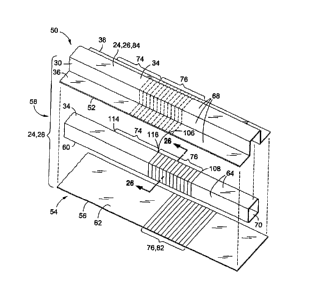
limiting the same, shown in FIG. 1 is a structure 10 such as a composite part
24 which may
comprise a stringer 26 formed of a base laminate 54, a primary laminate 50 and
a wrap
laminate 58. The stringer 26 may include first and second flanges 36, 38 which
may be
interconnected by a base center 40. The stringer 26 may include a pair of
first and second
webs 30, 32 which may extend outwardly from the first and second flanges 36,
38,
respectively, and which may be interconnected by a cap 34. The first flange 36
may intersect
with the base center 40 and first web 30 at a first noodle 44. The second
flange 38 may
intersect with the base center 40 and the second web 32 at a second noodle 46.
The base
laminate 54 may have a generally planar shape (Figure 4 and 12) and may be
comprised of
base plies 56 which may be formed of fiber reinforced material although any
material may
be used. The primary laminate 50 may have a generally hat-shaped cross-section
(Figure 4
and 10) along at least a portion of a length thereof and may be formed of
primary plies 52.
The wrap laminate 58 may have a closed cross-sectional shape (Figure 4 and 11)
along at
least a portion of a length thereof and may be formed of wrap plies 60. The
wrap laminate
may be nested within the primary laminate as shown in Figure 1, 3, and 4. The
primary
laminate may be flush against the base laminate to form a base portion
including the first and
second flanges (Figure 1, 3, and 4).
-8-
CA 02700796 2015-01-21
As can be seen in Figure 1, the primary plies 52 may comprise at least a
portion
of the first flange 36, first web 30, cap 34, second web 32 and second flange
38. The wrap
plies 60 may comprise at least a portion of the base center 40, first web 30,
second web 32
and cap 34. The base plies 56 may comprise at least a portion of the first
flange 36, base
center 40 and second flange 38. Each one of the first and second flanges 36,
38 may be
formed of a portion of the primary plies 52 and base plies 56. The base center
40 may be
formed of wrap plies 60 and base plies 56. Each one of the first and second
webs 30, 32
may be formed of primary plies 52 and wrap plies 60. Likewise, the cap 34 may
be formed
of primary plies 52 and wrap plies 60.
-8a-
CA 02700796 2010-04-16
1.
As described in greater detail below, the stringer 26 is configured such that
at least
one of the first and second webs 30, 32 transitions from a first angle 110 as
shown in Figures
and 9B to a second angle 112 as shown in Figures 6 and 9C within an angle
transition zone
74 as shown in Figures 4 and 9A. In addition, as shown in Figures 10-12, a ply
layup 48 of
5 the first and second flanges 36, 38 and the base center 40 as well as the
ply layup 48 of the
first and second webs 30, 32 and cap 34 may transition within a ply transition
zone 76. For
example, in an embodiment, the stringer 26 may be provided in a hat section 84
as shown in
Figures 5-7 which may be transitioned to a dual-blade section 86 as shown in
Figure 8
wherein the cap 34 may be at least partially removed as shown in Figure 3. By
transitioning
the orientation of the first and second webs 30, 32 from the first angle 110
to the second
angle 112 and/or by altering the ply layup 48 of the stringer 26, the need for
separate fittings
for stabilizing the webs may be eliminated.
For example, as shown in Figures 5-6, the system and method disclosed herein
provides a means for transitioning a cross-section of the stringer 26 from one
in which the
first and second webs 30, 32 may be oriented in a non-perpendicular angle
relative to the first
and second flanges 36, 38 as shown in Figure 5 to a substantially
perpendicular angle relative
to the first and second flanges 36, 38 as shown in Figure 6. Optionally, as
shown in Figure
6A, the first and second webs 30, 32 may transition to a non-perpendicular
angle that is near
perpendicular but which may include a draft angle 118 of up to five degrees or
more relative
to a substantially perpendicular orientation to facilitate removal of tooling
following curing of
the stringer 26. In addition, the system and method as disclosed herein
provides a means for
transitioning a ply layup 48 of the first and second flanges 36, 38, the first
and second webs
30, 32 and the base center 40 from a biased configuration 78, as shown in
Figures 13B and
14B, wherein the quantity of plies may be biased to one side of the first and
second noodles
44, 46, to an unbiased configuration 80, as also shown in Figures 13B and 14B,
wherein the
quantity of plies are generally uniformly distributed about the first and
second noodles 44, 46
as will be described in greater detail below.
Referring to Figure 2, shown is a structure 10 configured as an aircraft 120,
wing
124 having front and rear spars 18, 20 interconnected by a plurality of ribs
22 located at
spaced intervals along a span of the wing 124. The structure 10 may include
one or more
stringers 26 which may be coupled to a skin member 12 for stiffening thereof.
The stringers
26 may, in turn, be interconnected to the ribs 22. As shown in Figure 2, the
stringers 26 may
be configured as vent stringers 26 extending from an inboard 14 portion of the
wing 124 to an
-9-
CA 02700796 2010-04-16
I.
outboard 16 portion of the wing 124. In this manner, the closed hat section 84
of the stringers
26 may optionally function as a conduit for venting fuel vapors such as from
fuel tanks which
may be located at an inboard 14 portion of the wing 124. However, the stringer
26 may
function to vent any number of different fluids without limitation or serve as
a conduit for
other systems or elements. In this regard, each one of the stringers 26 may be
provided with
an opening 88 wherein a portion of the cap 34 which interconnects the first
and second webs
30, 32 may be removed. In such an arrangement, the stringer 26 may transition
from a hat
section 84 to a dual-blade section 86.
Referring to Figures 3-8 and 10-14B, shown in Figure 3 is a perspective
illustration of one of the stringers 26 coupled to a skin member 12. As can be
seen, the
stringer 26 may include the angle transition zone 74 wherein the orientation
of at least one of
the first and second webs 30, 32 transitions from the first angle 110 as shown
in Figure 5 to
the second angle 112 as shown in Figures 6-8. Furthermore, Figure 10
illustrates the ply
transition zone 76 wherein a ply layup 48 of the base portion 28 and the first
and second webs
30, 32 may transition from a biased configuration 78 at the first ply zone end
106 as shown in
Figures 13B and 14B, to an unbiased configuration 80 at the second ply zone
end 108 as also
shown in Figures 13B and 14B. In this regard, the ply transition zone 76
comprises a
location along the stringer 26 wherein the plies of the laminates that
interface with one
another to form the stringer 26 are incrementally increased in one laminate in
correspondence
with an incremental decrease in the plies of the facing laminate. For example,
referring
briefly to Figure 18, shown is an intersection of the base laminate 54, wrap
laminate 58 and
primary laminate 50 wherein the base plies 56, wrap plies 60 and primary plies
52 comprise
the biased configuration 78 at the first ply zone end 106 of the ply
transition zone 76.
Referring briefly to Figure 23, shown is the unbiased configuration 80 of the
base laminate
54, wrap laminate 58 and primary laminate 50 at the second ply zone end 108 of
the ply
transition zone 76. Advantageously, by incrementally increasing (i.e., adding)
and decreasing
(i.e., dropping) plies within the ply transition zone 76, the stringer 26 can
be morphed from
the biased configuration 78 to the unbiased configuration 80.
Referring to Figure 3, it should be noted that the stringer 26 may include one
or
more angle transition zones 74 and/or one or more ply transition zones 76 and
is not limited
to a single one of each. Furthermore, the present disclosure contemplates a
stringer 26
configuration having only one or more ply transition zones 76 and not having
an angle
transition zone 74. Conversely, the present disclosure contemplates a
stringer 26
-10-
CA 02700796 2010-04-16
configuration having only one or more angle transition zones 74 and not having
a ply
transition zone 76. Even further, the present disclosure contemplates an
arrangement wherein
only one of the first and second webs 30, 32 of the stringer 26 includes the
angle transition
zone 74. The present disclosure also contemplates a stringer 26 configuration
having only a
single one of the first and second flanges 36, 38 and including only a single
one of the first
and second webs 30, 32 extending outwardly from the single one of the first
and second
flanges 36, 38.
Referring now to Figure 4, shown is an exploded perspective illustration of
the
base laminate 54, wrap laminate 58 and primary laminate 50 which make up the
stringer 26
as shown in Figure 3. In this regard, Figure 4 illustrates a configuration of
each one of the
laminates prior to assembling for co-curing or bonding to form the stringer
26. As can be
seen, the location of the ply transition zone 76 of the primary laminate 50
corresponds to the
location of the ply transition zone 76 of the wrap laminate 58. Likewise, the
ply transition
zone 76 of the wrap laminate 58 and primary laminate 50 correspond to the ply
transition
zone 76 of the base laminate 54. Even further, the angle transition zone 74 of
the wrap
laminate 58 corresponds to the angle transition zone 74 of the primary
laminate 50.
Referring to Figure 5, shown is a sectional illustration of the stringer 26
taken
along line 5-5 of Figure 3 and illustrating the orientation of the first and
second webs 30, 32
at the first angle 110. As was earlier indicated, the first angle 110
transitions to the second
angle 112 along the angle transition zone 74. As shown in Figure 5, at least
one of the first
and second webs 30, 32 may define a non-perpendicular orientation at the first
angle zone
end 114 relative to the base portion 28. In an embodiment, each one of the
first and second
webs 30, 32 may be angled inwardly relative to one another at the first angle
zone end 114.
In this configuration, the hat section 84 of the stringer 26 defines a
trapezoidal cross-sectional
configuration. However, the stringer 26 may define any cross sectional
configuration,
without limitation, including any closed cross sectional configuration.
Referring to Figure 6, shown is a sectional illustration taken along line 6-6
of
Figure 3 and illustrating an orientation of the first and second webs 30, 32
at the second angle
zone end 116 of the angle transition zone 74. In this regard, each one of the
first and second
webs 30, 32 is illustrated as defining a substantially perpendicular
orientation relative to the
base portion 28 (i.e., relative to the first and second flanges 36, 38). It
should be noted that
although the stringer 26 is illustrated as having a non-perpendicular
orientation of the first and
second webs 30, 32 at the first angle zone end 114 of the angle transition
zone 74, the first and
-11-
CA 02700796 2010-04-16
second webs 30, 32 may be oriented substantially perpendicularly relative to
the base portion
28 at the first angle zone end 114. Likewise, although the first and second
webs 30, 32 are
illustrated as defining a substantially perpendicular orientation at the
second angle zone end
116 of the angle transition zone 74, the first and second webs 30, 32 may
define a non-
perpendicular orientation relative to the base portion 28.
Even further, it is contemplated that the first and second webs 30, 32 may
transition from non-perpendicular orientations relative to the base portion 28
or to different
non-perpendicular orientations relative to the base portion 28. Additionally,
the present
disclosure contemplates an orientation of the first web 30 that is different
than an orientation
of the second web 32 at any point along the stringer 26 including at any point
along the angle
transition zone 74 of the first and second webs 30, 32. However, for purposes
of improving
the stability of the first and second webs 30, 32 at a location of the
stringer 26 wherein the cap
34 is removed, the first and second webs 30, 32 may be oriented substantially
perpendicularly
relative to the base portion 28.
Referring briefly to Figure 7, shown is a sectional illustration taken alone
line 7-7
of Figure 3 and illustrating an increased thickness tbase center of the base
center 40 at the second
ply zone end 108 within the ply transition zone 76 as compared to the
thickness tbase center of the
base center 40 at the first ply zone end 106. The increased thickness tbase
center of the base
center 40 is a result of an incremental increase in the quantity of the wrap
plies 60 and base
plies 56 within the within of the ply transition zone 76 as will be described
in greater detail
below.
Referring briefly to Figure 8, shown is a sectional illustration taken alone
line 8-8
of Figure 3 and illustrating a transition of the stringer 26 from a hat
section 84 to a dual-blade
section 86. The dual-blade section 86 may be formed by removing at least a
portion of the cap
34 along the length of the stringer 26 as is illustrated in Figure 3. The cap
34 may preferably
be removed at a location outside of the ply transition zone 76 and the angle
transition zone 74
although removal of the cap 34 may occur at any position along the length of
the stringer 26.
Referring to Figures 9A-9D, shown in Figure 9A is a plan view of the stringer
26
along the angle transition zone 74 wherein at least one of the first and
second webs 30, 32
transitions from the first angle 110 to the second angle 112. Figure 9B is a
cross-sectional
illustration of the stringer 26 taken at the first angle zone end 114 wherein
at least one of the
first and second webs 30, 32 may be oriented at the first angle 110. Figure 9C
is a cross-
sectional illustration of the stringer 26 taken at the second angle zone end
116 zone wherein
-12-
CA 02700796 2010-04-16
at least one of the first and second webs 30, 32 may be oriented at the second
angle 112.
Figure 9D is a schematic illustration of the angle transition zone 74
illustrating an
embodiment of the stringer 26 wherein at least one of the first and second
webs 30, 32 may
vary in transition rate. For example, the transition may initiate with the
first and second webs
30, 32 being oriented in a non-perpendicular relationship relative to the
first and second
flanges 36, 38. In an embodiment, the first and second webs 30, 32 may be
oriented at a 75
degree angle relative to the base portion 28 although the first angle 110 may
comprise any
orientation relative to the base portion 28 and is not limited to that which
is illustrated.
Referring still to Figure 9D, the transition from the first angle 110 to the
second
angle 112 may include linear or non-linear angle transition rates. For
example, Figure 9D
illustrates an initial transition rate of 0.17 degrees per inch of the first 6
inches of the angle
transition zone 74 in a direction from the first angle zone end 114 to the
second angle zone end
116. The transition rate may increase to a higher rate of change such as the
illustrated 0.20
degrees per inch transition rate within the next 10 inches of the angle
transition zone 74. A
more aggressive transition rate such as the 0.32 degrees per inch transition
may be provided
within the next 28 inches of the angle transition zone 74. The angle
transition zone 74 may
then provide for a gradual reduction in the transition rate. For example, the
next 10 inches
may include a transition rate of 0.20 degrees per inch followed by a
transition rate of 0.17
degrees per inch in the final 6 inches of the angle transition zone 74. As may
be appreciated,
the transition of the first angle 110 to the second angle 112 may comprise a
non-linear
transition rate as indicated above although any combination of linear and non-
linear translation
rates may be incorporated into the angle transition zone 74. Furthermore, as
was earlier
mentioned, the orientations and transition rates of the first web 30 may be
different than the
orientations and transition rates of the second web 32 at any location along
the stringer 26.
Referring to Figure 10, shown is the primary laminate 50 in an orientation
that has
been flipped vertically relative to the orientation of the primary laminate 50
as shown in
Figure 4 in order to better illustrate a ply layup 48 of the primary laminate
50 within the ply
transition zone 76. More specifically, Figure 10 illustrates a plurality of
primary plies 52
which make up the primary laminate 50 and which are shown in exaggerated
thicknesses in
order to illustrate the incremental or stepwise decrease in the quantity of
primary plies 52 from
the first ply zone end 106 of the ply transition zone 76 to the second ply
zone end 108 thereof.
Figure 10 further illustrates the primary plies 52 of the primary laminate 50
being disposed on
a cure mold 100 such that the primary ply 52 nearest the cure mold 100 assumes
the shape of
-13-
CA 02700796 2010-04-16
the tool surface 68. The primary laminate 50 comprises at least a portion of
the first and
second flanges 36, 38 which collectively define the base portion 28. Likewise,
the primary
laminate 50 comprises at least a portion of the first and second webs 30, 32.
In this regard, the
primary laminate 50 is combined with the wrap laminate 58 as illustrated in
Figure 11 to form
the first and second webs 30, 32 and the cap 34 of the stringer 26 as will be
described in
greater detail below.
The primary laminate 50 may also include the angle transition zone 74 wherein
at
least one of the first and second webs 30, 32 transitions from the first angle
110 at the first
angle zone end 114 as shown in Figure 9B to the second angle 112 at the second
angle zone
end 116 as shown in Figure 9C. The angle transition zone 74 is shown in Figure
10 as being
positioned in series relative to the ply transition zone 76. However, it is
contemplated that the
angle transition zone 74 and the ply transition zone 76 may be placed in
partial or complete
overlapping relationship relative to one another. In this regard, for a
completely overlapping
relationship of the angle transition zone 74 with the ply transition zone 76,
the first and second
webs 30, 32 transition from the first angle 110 to the second angle 112
simultaneous with the
ply layup 48 transitioning from the first ply zone end 106 to the second ply
zone end 108.
However, for purposes of the present disclosure, the angle transition zone 74
is illustrated and
described as being in series with and disposed adjacent to the ply transition
zone 76. Figure
10 further illustrates a succession of lap splices 72 wherein successive
primary plies 52 of the
primary laminate 50 overlap one another as the quantity of primary plies 52
incrementally
decrease or are dropped within the ply transition zone 76. In this regard,
although Figure 10
illustrates the primary plies 52 being decreased or dropped along a bottom
surface of the
stringer 26, it is contemplated that the primary plies 52 may be decreased or
dropped along a
top surface of the stringer 26.
Referring to Figure 11, shown is the wrap laminate 58 comprised of an
incrementally increasing quantity of wrap plies 60 corresponding to the
incremental decrease
or drop in the quantity of primary plies 52 of the primary laminate 50 as
shown in Figure 10.
More specifically, the lap splices 72 of the overlapping wrap plies 60 are
preferably positioned
in registration to the lap splices 72 of the incrementally decreasing primary
plies 52 as
illustrated in Figure 10. The wrap laminate 58 may be formed by laying up the
wrap plies 60
about a mandrel 92 such as a foam 98 mandrel or a bladder 96 which may be
inflatable in
order to permit removal of the mandrel 92 following curing of the wrap plies
60. However,
the wrap laminate 58 may be formed by laying up wrap plies 60 about any
suitable mandrel
-14-
CA 02700796 2010-04-16
. .
configuration and is not limited to foam 98 or a bladder 96. The mandrel 92
may include
mandrel side walls 93. Removal of the mandrel 92 following laying up and
curing of the wrap
plies 60 results in the formation of the vent surfaces 70 on the interior side
of the wrap
laminate. The vent surfaces 70 may collectively define an interior portion of
the wrap
-- laminate 58.
Referring to Figure 12, shown is the base laminate 54 having a ply transition
ramp
82 or ply transition zone 76 wherein the base plies 56 are laid up on a mold
line surface 69 of a
base mold 90 and where the quantity of base plies 56 may be incrementally
increased or added
within the ply transition zone 76. As shown in Figure 4 through 12, the layup
of the primary
-- plies 52, wrap plies 60 and base plies 56 is preferably in equal increments
and in registration
with one another such that the respective plies overlap with one another at
the lap splices 72.
However, the layup of the primary plies 52, wrap plies 60 and base plies 56
may be in varying
or unequal increments or in any suitable increment along the ply transition
zone 76.
Referring to Figures 13A to 13B, shown is a layup of the primary plies 52 to
form
-- the primary laminate 50 within the ply transition zone 76. As can be seen
in Figure 13B, the
base laminate 54 defines a base-primary interface 62 with the primary laminate
50. The first
and second flanges 36, 38 transition from a biased configuration 78 at the
first ply zone end
106 to an unbiased configuration 80 at the second ply zone end 108 as measured
about the
base-primary interface 62 as shown in Figure 13A. In an embodiment, the
primary laminate
-- 50 includes lap splices 72 between successive decreases or drops of the
primary plies 52 of the
primary laminate 50 (or increases in the base plies 56 of the base laminate
54). Although a .75
inch lap splice 72 is illustrated and described in the present disclosure, the
lap splice 72 may
comprise any suitable distance. For example, the lap splice 72 may comprise
anywhere from
.01 inch or less to 2.0 inches or more between successive increases or
decreases in plies. In an
-- embodiment, the lap splices 72 are preferably sized in proportion to a
thickness of the plies.
The length of the lap splice 72 may be sized at a predetermined multiple of
the thickness of the
plies. For example, for a ply thickness of .0075 inch, a multiple of 100 may
dictate a .75 inch
lap splice. However, the lap splice 72 may be provided in any length and a not
limited to a
given multiple of the thickness of the plies. Furthermore, the lap splices 72
may be arranged
-- in any increment within the ply transition zone 76 including equal
increments, unequal
increments, or varying combinations thereof
Referring to Figures 14A to 14B, shown is an arrangement similar to that which
is
shown in Figures 13A-13B wherein the cap 34 and the first and second webs 30,
32 comprise
-15-
CA 02700796 2010-04-16
. .
a biased configuration 78 at the first ply zone end 106 transitioning to an
unbiased
configuration 80 at the second ply zone end 108 as measured about the primary-
wrap interface
64. As can be seen in Figure 14B, the incremental decrease in the quantity of
primary plies 52
of the primary laminate 50 is in correspondence with the incremental increase
in wrap plies 60
of the wrap laminate 58 to form the first and second webs 30, 32. Figure 14B
illustrates the
lap splice 72 in correspondence with the lap splice 72 illustrated in the
first and second flanges
36, 38 and described above in Figure 13B.
Referring to 15A to 15B, shown is the base center 40 comprised of wrap plies
60
of the wrap laminate 58 and base plies 56 of the base laminate 54. As can be
seen, the
increase or adding of wrap plies 60 and the increase or adding of base plies
56 results in an
overall increase in the thickness tbase center of the base center 40. For
example and referring
briefly to Figures 6 and 7, shown in Figure 6 is an initial thickness t
-base center of the base center
40 at the first ply zone end 106 of the ply transition zone 76. Figure 7
illustrates an increased
thickness t
-base center of the base center 40 at the second ply zone end 108 as a result
of the
incremental increase in the quantity of wrap plies 60 and base plies 56. As
can be seen in
Figure 15B, the wrap laminate 58 and base laminate 54 define the wrap-base
interface 66. In
the embodiment shown, the ply layup 48 of the wrap plies 60 and base plies 56
is such that the
base center 40 may have a first laminate thickness 136 at the first ply zone
end 106 and a
second laminate thickness 138 at the second ply zone end 108. However, the
second laminate
thickness 138 may comprise a greater quantity of wrap plies 60 and base plies
56 as compared
to the first laminate thickness 136. Furthermore, the second laminate
thickness 138 may
comprise an equal quantity or a reduced quantity of wrap plies 60 and base
plies 56 as
compared to the first laminate thickness 136 depending, in part, upon the
initial quantity of
plies in the wrap laminate 58 and base laminate 54 at the first ply zone end
106 and/or
depending on whether such plies are increasing or decreasing in quantity
within the ply
transition zone 76
Referring to Figures 16A-16C, shown in Figure 16C is a chart illustrating a
ply
layup 48 of the first and second flanges 36, 38 referenced in Figure 16A and
which may
correspond to a ply layup 48 of the first and second webs 30, 32 referenced in
Figure 16B.
The chart illustrates an arrangement of fabric plies 102 and tape plies 104 of
varying
orientations and is provided for illustration purposes only and is not to be
construed as limiting
alternative ply arrangements. The chart illustrates a layup comprising a
fabric ply 102 of the
primary laminate 50 disposed on the tool surface 68 followed by a layup of
tape plies 104
-16-
CA 02700796 2010-04-16
, .
oriented at 0 degrees, plus 45 degrees, minus 45 degrees and 90 degrees, etc.
It should be
noted that the specific fiber orientations of the various wrap plies 60,
primary plies 52 and
base plies 56 may be provided in any arrangement and may be optimized for a
given set of
manufacturing, environmental and/or static and dynamic loading conditions,
etc. In this
regard, the arrangement of tape plies 104 and fabric plies 102 may be provided
in a variety of
alternative patterns other than that which is shown in Figure 16C.
However, Figure 16C illustrates a feature of the present disclosure wherein
the ply
layup 48 of the primary plies 52, wrap plies 60 and base plies 56 which make
up the first and
second flanges 36, 38 and the first and second webs 30, 32 may transition from
a biased
configuration 78 at the first ply zone end 106 to an unbiased configuration 80
at the second ply
zone end 108. For example, in the biased configuration 78, the first ply zone
end 106 on the
left-hand side of the chart of Figure 16C illustrates the quantity of primary
plies 52 that make
up the primary laminate 50 as being greater in number that the single wrap ply
60 and the
single base ply 56 which is illustrated as a fabric ply 102. In the unbiased
configuration 80 at
the second ply zone end 108 on the right-hand side of the chart of Figure 16C,
the quantity of
primary plies 52 are equal in number to the quantity of tape plies 104 which
make up the wrap
plies 60 and base plies 56.
Figures 17A-17B illustrate a ply layup 48 of the base center 40 of the
stringer 26
within the ply transition zone 76 wherein the ply layup 48 transitions from a
first laminate
thickness 136 to a second laminate thickness 138 which may be increased in
thickness as
compared to the first laminate thickness 136. A can be seen, the ply layup 48
of the base plies
56 may incrementally increase in correspondence with the incremental increase
of the wrap
plies 60. The ply layup 48 of the base plies 56 as shown in Figure 17B
corresponds to the ply
layup 48 of the base plies 56 as shown in Figure 16C. As may be appreciated,
the specific ply
layup 48 of the base center 40 may be altered by altering the ply layup 48 of
the wrap plies 60
or by altering the ply layup 48 of the base plies 56. In this regard, although
the base center 40
illustrates an arrangement wherein the base plies 56 mirror the wrap plies 60
about the wrap-
base interface 66, a non-mirrored arrangement may be provided
Referring to Figures 18 through 23, shown are enlarged sectional illustrations
of
the intersection of the first web 30 with the first flange 36 at the first
noodle 44 and which may
optionally mirror the arrangement at the intersection of the second web 32
with the second
flange 38. As can be seen, Figures 18 through 23 illustrate the transition in
the primary
laminate 50 and wrap laminate 58 from a biased configuration 78 at the first
ply zone end 106
-17-
CA 02700796 2010-04-16
to an unbiased configuration 80 at the second ply zone end 108, and the
transition of the wrap-
base interface 66 from a first laminate thickness 136 to a second laminate
thickness 138. For
example, Figure 18 illustrates a cross-section of the first web 30 with the
first flange 36 prior
to the initiation of the transition of the ply layup 48. As can be seen, the
ply layup 48 of the
primary plies 52 comprise a plurality of tape plies 104 and a single fabric
ply 102 on an
interior side of the ply layup 48 although the ply layup 48 may comprise
alternative ply
materials on the interior side of the ply layup 48 and any number of
alternative ply materials
laid over the initial ply. In this regard, Figure 18-25 are illustrative of a
sequence about which
the ply layup 48 of the stringer 26 may be transitioned and is not to be
construed as limiting
alternative ply arrangements of the stringer 26. The ply layup 48 of the wrap
laminate 58 may
comprise any number of ply materials. For example, the ply layup 48 may
include the single
fabric ply 102 as shown which may be laid up on a suitable mandrel 92 such as
a bladder 96 or
a foam 98 mandrel 92. The base laminate 54 is shown also as comprising a
fabric ply 102
although any ply material may be used. As shown in Figure 18, the stringer 26
may have the
biased configuration 78 at the base-primary interface 62 and primary-wrap
interface 64 at the
first ply zone end 114. Figure 18 also illustrates the first laminate
thickness 136 at the wrap-
base interface 66.
Figure 19 illustrates the initial ply transition wherein the fabric ply 102
for the
primary laminate 50 illustrated in Figure 18 has been dropped. Simultaneously,
a wrap ply 60
has been added to the wrap laminate 58 and to the base laminate 54. In this
regard, the overall
thickness t
-flange of the first flange 36 which is comprised of the base laminate 54 and
primary
laminate 50 remains constant as does the overall thickness twth of the first
web 30. A lap splice
72 is formed at the primary-wrap interface 64. Likewise, a lap splice 72 is
formed at the base-
primary interface 62 and at the wrap-base interface 66. Figure 19 illustrates
that the primary-
wrap interface 64 comprises a lap splice 72 formed of tape plies 104. However,
as was
indicated above, plies having any fiber orientation may be used. Furthermore,
it is also
contemplated that in each ply transition and at each interface, the lap
splices 72 that occur
within the ply transition zone 76 may comprise lap splices 72 of tape plies
104 having
differing fiber orientations.
Referring to Figure 20, shown is a second ply transition wherein one of the
primary
plies 52 is dropped and a wrap ply 60 is added to the wrap laminate 58 while a
base ply 56 is
added to the base laminate 54. As can be seen in Figure 20, the ply transition
zone 76 may be
configured such that a combined thickness of the base laminate 54 and primary
laminate 50 is
-18-
CA 02700796 2010-04-16
,
maintained as is the combined thickness of the wrap laminate 58 and primary
laminate 50.
However, the combined thickness of the wrap laminate 58 and the base laminate
54 which
form the base center 40 increases in thickness by two plies. Figure 21
illustrates a third ply
transition wherein a primary ply 52 is dropped from the primary laminate 50
while a wrap ply
60 and a base ply 56 are added to the wrap laminate 58 and base laminate 54,
respectively,
resulting in an increase in the thickness those center of the base center 40
and maintaining a
thickness ange _ _
GõI
of the first flange 36 and thickness tweb of the first web 30. Figure 22
illustrates
a second to last transition of plies of the ply transition zone 76 wherein a
primary ply 52 is
dropped and a wrap ply 60 is added to the wrap laminate 58 and a base ply 56
is added to the
base laminate 54. In an embodiment, as illustrated, the stringer 26 may
comprise a fabric ply
102 extending along the mandrel 92 such that the fabric ply 102 forms the vent
surface 70 of
the stringer 26.
Referring to Figure 23, shown is a last ply transition step within the ply
transition
zone 76 wherein fabric plies 102 are added along the first noodle 44. As can
be seen, the ply
layup 48 of the stringer 26 at the second ply zone end 108 provides an
unbiased configuration
80 at the base-primary interface 62 as well as at the primary-wrap interface
64. The wrap-base
interface 66 transitions from a first laminate thickness 136 as shown in
Figure 18 to a second
laminate thickness 138 at the second ply zone end 108 as shown in Figure 23.
As was
indicated above, Figure 23 illustrates an arrangement of plies including,
namely, tape plies 104
and fabric plies 102. However any arrangement of ply layups may be provided
and is not
limited to that which is illustrated in the Figures. For example, fabric plies
102 and tape plies
104 may be positioned at any location within each of the ply layups of the
wrap laminate 58,
base laminate 54 and primary laminate 50. Other ply materials may also be used
in the ply
layup 48.
Referring to Figures 24-25, shown is the first noodle 44 or radius filler 42
illustrating a transition thereof within the angle transition zone 74 in
correspondence with the
angle transition zone 74 of the stringer 26 illustrated in Figures 5, 6, 9A
and 9D. As can be
seen in Figure 24, the first noodle 44 transitions from the first angle 110 at
the first angle zone
end 114 shown in Figure 9B to the second angle 112 as shown in Figure 25 at
the second
angle zone end 116 as shown in Figure 9C. The second noodle 46 may include a
similar
transition to the first noodle 44 but in mirror image. The first and second
noodles 44, 46 may
be specifically shaped or preformed to correspond to the changing orientation
of the first and
second angles 110, 112 within the angle transition zone 74. The first and
second noodles 44,
-19-
CA 02700796 2010-04-16
46 may be formed by any suitable means known in the art and may include the
use of woven
fabric as material for the first and second noodles 44, 46 and forming or
cutting as required to
fill the radius defined between the primary laminate 50, base laminate 54 and
wrap laminate
58.
Referring briefly to Figure 26, shown is a cross-sectional illustration of the
ply
layup 48 of wrap plies 60 that form the wrap laminate 58. As was earlier
mentioned, the wrap
laminate 58 may be formed by laying up the wrap plies 60 about a suitable
mandrel 92. For
example, Figure 11 illustrates the incremental increase in the quantity of
wrap plies 60 which
are formed about the mandrel 92 within the ply transition zone 76 and are
preferably arranged
in correspondence with the incremental decrease in the primary plies 52 and
the incremental
increase in the base plies 56. In an embodiment illustrated in Figure 26, the
axially oriented
lap splices 72 of the wrap plies 60 are preferably positioned to fall within
the cap 34 of the
stringer 26. However, it is contemplated that the lap splices 72 may be
positioned to fall
within the first and second flanges 36, 38, within the base center 40 or any
combination
thereof. Furthermore, the extent of overlap of the lap splices 72 as shown in
Figure 26 may be
in proportion to the total number of wrap plies 60 that are added within the
ply transition zone
76. In this regard, the spacing between the lap splices 72 as shown in Figure
26 is preferably
evenly distributed across a width of the cap 34 which may be defined as the
distance between
the first and second webs 30, 32 of the stringer 26. The spacing between the
lap splices 72
may be linear or may be non-linear and may vary at any portion across a width
of the cap 34.
Furthermore, the spacing between the lap splices 72 may be uniformly
distributed along any
one of the first 30 and second webs 32 or along the base center 40 or along
any combination
thereof
Referring to Figure 27, shown is a perspective illustration of an aircraft 120
which
may incorporate one or more of the stringers 26 as disclosed herein. As can be
seen in Figure
27, the aircraft 120 may comprise a fuselage 122 having a pair of wings 124
and having a tail
section 128 which may include a vertical stabilizer 132 and horizontal
stabilizers 130 and
which may further include control surfaces 126 and propulsion units 134. The
aircraft 120 as
shown in Figure 27 is generally representative of a variety of vehicles which
may incorporate
the stringer 26 as described herein. In this regard, the stringer 26 may be
incorporated into any
system, subsystem, assembly, application, structure 10 or vehicle including
any marine, land,
air and/or space vehicle.
-20-
CA 02700796 2010-04-16
, .
In an embodiment, the aircraft 120 as shown in Figure 27 may incorporate
stringers
26 in the fuselage 122 section and/or in the wing 124 section wherein the
stringers 26 may be
coupled to skin members 12 in order to form upper and lower surfaces of the
wings 124. As
was earlier indicated, such stringers 26 may provide dual functionality in
venting fuel vapors
from an inboard 14 section of the wing 124 to an outboard section thereof in
addition to a
primary load carrying capability of the stringers 26. In this regard, the
present disclosure
provides a composite aircraft 120 structure 10 which may comprise a skin
member 12 having
a stringer 26 mounted thereto and which transitions to a hat section 84 as
illustrated in Figures
5-7 to a dual-blade section 86 as illustrated in Figure 8. As was earlier
mentioned, the dual-
blade section 86 may be formed by removing at least a portion of the cap 34
along the length
of a stringer 26. The cap 34 may preferably be removed at any location outside
of the ply
transition zone 76 and the angle transition zone 74. However, it is
contemplated that removal
of the cap 34 may be at any position and may occur within the ply transition
zone 76 and/or
within the angle transition zone 74.
Referring now to Figure 28, shown is a methodology of forming the stringer 26
having the base portion 28 and the pair of first and second webs 30, 32 which
extend
outwardly therefrom as illustrated in Figures 1-8. In an embodiment, the
methodology for
forming the stringer 26 may comprise initially forming the base laminate 54
which may
include laying up the base plies 56 on the base mold 90 in step 150 as
illustrated in Figure 12.
Formation of the base laminate 54 may include incorporation of the ply
transition zone 76
wherein the ply layup 48 of the base plies 56 that comprise the base portion
28 are altered as
described above with reference to Figures 12-23. More specifically, the
methodology may
comprise step 152 including increasing the quantity of the base plies 56
incrementally within
the ply transition zone 76 such that the thickness of the base laminate 54
increases from the
first ply zone end 106 to the second ply zone end 108 as best seen in Figure
12.
Step 154 may comprise forming the primary laminate 50 by laying up the primary
plies 52 on the cure mold 100 as best seen in Figure 10. The primary laminate
50 may
comprise at least a portion of the first and second flanges 36, 38 and first
and second webs 30,
32 which may be interconnected by the cap 34. The cure mold 100 may include
cure mold
side walls 101 which transition from the first angle 110 at the first angle
zone end 114 to the
second angle 112 at the second angle zone end 116 where the first and second
angles 110, 112
are defined relative to the base portion 28 as best seen in Figures 5-6. In
this regard, the cure
mold 100 may incorporate a changing angle of the cure mold side walls 101
similar to that
-21-
CA 02700796 2010-04-16
. .
which is illustrated in Figure 9A to 9D. Regarding the ply layup 48 of the
primary laminate
50, step 156 may comprise decreasing the quantity of the primary plies 52
incrementally
within the ply transition zone 76. As was earlier mentioned, the incremental
decrease or drop
in the quantity of primary plies 52 that are laid up on the cure mold 100 is
preferably in
correspondence with the incremental increase in the quantity of base plies 56
that are laid out
in step 152.
Referring to Figure 11, step 158 may comprise forming the wrap laminate 58 by
laying up the wrap plies 60 about a suitable mandrel 92 such as a foam 98
mandrel or an
inflatable bladder 96 or other suitable mandrel configuration. As best seen in
Figure 11, the
mandrel 92 includes mandrel side walls 93 that are formed complementary to the
cure mold
side walls 101. More specifically, the cure mold side walls 101 transition
from the first angle
110 to the second angle 112 within the angle transition zone 74. Likewise, the
mandrel side
walls 93 transition from the first angle 110 to the second angle 112 in
correspondence with the
transition of the cure mold side walls 101. For example, as described above
with reference to
Figures 9A and 9D, in an embodiment, the transition from the first angle 110
to the second
angle 112 may occur at a varying transition rate. However, a variety of
alternative transition
rates may be incorporated into the angle transition zone 74 such that the
methodology is not
limited to that which is illustrated and disclosed in Figures 9A-9D.
Regarding the transition of plies in the wrap laminate 58 shown in Figure 11,
step
160 may comprise incrementally increasing the quantity of wrap plies 60 within
the ply
transition zone 76. The incremental increase in the wrap plies 60 is
preferably in
correspondence with the incremental decrease or drop in the primary plies 52
and the
incremental increase in the base plies 56. For example, as shown in Figure 4,
the angle
transition zones 76 incorporated into each one of the base laminate 54, wrap
laminate 58 and
primary laminate 50 are preferably registered or aligned with one another such
that assembly
of the wrap laminate 58 into the primary laminate 50 results in registration
of the lap splices
72 relative to one another. Likewise, assembly of the base laminate 54 to the
combination of
the wrap laminate 58 and primary laminate 50 also preferably results in
registration of the lap
splices 72. In this regard, step 162 comprises assembling the stringer 26 by
inserting the wrap
laminate 58 into the primary laminate 50. For example, in an embodiment,
formation of the
stringer 26 may comprise installing the wrap laminate 58 as illustrated in
Figure 11 into the
primary laminate 50 positioned on the cure mold 100 as shown in Figure 10. The
mandrel 92
may also be installed in the wrap laminate 58 during step 162.
-22-
CA 02700796 2010-04-16
Step 164 may comprise placing at least one of the first and second noodles 44,
46
as shown in Figures 24 and 25 along the wrap laminate 58 and primary laminate
50 such that
the cross-sectional configuration of the first and second noodles 44, 46
corresponds to the
wrap laminate 58 and primary laminate 50 along the length of the stringer 26.
More
specifically, the first and second noodles 44, 46 are preferably provided with
a cross-sectional
configuration that includes the first angle 110 at the first angle zone end
114 and the second
angle 112 at the second angle zone end 116. As was earlier indicated, the
first and second
noodles 44, 46 may be formed by any suitable means including pultrusion,
extrusion, hand
layup or any other suitable forming process.
Step 166 in the methodology of forming the stringer 26 may comprise adding the
base laminate 54 to the wrap laminate 58 and primary laminate 50 after
installation of the first
and second noodles 44, 46. As was earlier indicated, the ply transition zone
76 in the base
laminate 54 is preferably positioned in correspondence to the ply transition
zones 76 of the
base laminate 54 and wrap laminate 58 such that the lap splices 72 are in
registration with one
another. Following assembly, the base laminate 54, wrap laminate 58 and
primary laminate
50 may be integrated into a unitary structure 10 by co-curing in step 168
through the
application of a predetermined amount of pressure and/or heat for a
predetermined period of
time using any suitable curing or bonding process.
Step 170 may comprise forming the opening 88 in the stringer 26 between the
first
and second flanges 36, 38 by removing at least a portion of the cap 34. For
example, as shown
in Figure 3, the cap 34 may be removed at a location that is outside the ply
transition zone 76
and the angle transition zone 74 although the cap 34 may be removed at any
location along the
stringer 26. The opening 88 may provide a means for reducing the stiffness of
the stringer 26
and for venting the stringer 26.
With reference now to Figure 29, the present disclosure also includes a
methodology for transitioning the stringer 26 from a hat section 84 to a dual-
blade section 86.
As was earlier indicated, the stringer 26 may comprise the base portion 28
including the first
and second flanges 36, 38 interconnected by the base center 40 as best seen in
Figures 5-8.
The stringer 26 may further comprise the first and second webs 30, 32 which
may extend
outwardly from the base portion 28 and which may be interconnected by the cap
34 which
may extend at least partially along a length of a stringer 26.
Step 180 of the methodology comprises altering the orientation of at least one
of
the webs of the stringer 26 from the first angle 110 to the second angle 112
within the angle
-23-
CA 02700796 2010-04-16
transition zone 74. For example, as illustrated in Figures 5-6, at least one
of the first and
second webs 30, 32 may be oriented at the first angle 110 which may be a
nominal or non-
perpendicular angle relative to the base portion 28. At the second angle zone
end 116, at least
one of the first and second webs 30, 32 may be transitioned to the second
angle 112 which
may comprise a substantially perpendicular orientation thereof relative to the
base portion 28
although the second angle 112 which may comprise a non-perpendicular
orientation. The
transition rate with which the first and second webs 30, 32 transition from
the first angle 110
to the second angle 112 along the angle transition zone 74 may be linear or
non-linear. For
example, as illustrated in Figures 9A to 9D and as described above, the angle
transition may
comprise an initially mild transition rate with an increasingly aggressive
transition rate
towards a center of the angle transition zone 74. The transition rate may then
reduce from the
center of the angle transition zone 74 to the second angle zone end 116.
Step 182 may comprise altering the ply layup 48 of at least one of the first
and
second webs 30, 32 of the stringer 26. In addition, step 182 may comprise
altering the ply
layup 48 of the base portion 28 including the first and second flanges 36, 38.
The alteration of
the ply layups may occur within the ply transition zone 76 as best seen in
Figures 10-23 and
which illustrate the incremental decrease in the quantity of primary plies 52
and the
corresponding incremental increase in the quantity of wrap plies 60 and base
plies 56. More
specifically, the methodology may comprise dropping a primary ply 52 when
adding a wrap
ply 60 and a base ply 56. In an embodiment, the dropping of primary plies 52
and adding of
wrap plies 60 and base plies 56 may occur in any suitable increment such as,
without
limitation, increments of approximately .01 inch to approximately 2 inches or
more. The step
of altering the ply layup 48 of the base portion 28 and the first and second
webs 30, 32 within
the ply transition zone 76 may comprise transitioning from the biased
configuration 78 at the
first ply zone end 106 to the unbiased configuration 80 at the second ply zone
end 108 as
shown in Figures 13A-23 and as described above. However, the stringer 26 may
be
configured such that the biased configuration 78 is provided at the first and
second ply zone
ends 106, 108.
Step 186 of the methodology of forming the stringer 26 may further comprise
maintaining an essentially constant thickness tflange of at least one of the
first and second
flanges 36, 38, and at least one of the first and second webs 30, 32 as well
as the thickness of
the cap teap within the ply transition zone 76. For example, as shown in
Figures 18-23, the
total quantity of plies in the primary laminate 50 and base laminate 54 that
make up the first
-24-
CA 02700796 2010-04-16
flange 36 and the total quantity of plies in the primary laminate 50 and wrap
laminate 58 that
make up the first web 30 may be maintained in equal number within the ply
transition zone 76.
However, it should be noted that the quantity of plies 52, 56, 60 may be
increased or decreased
within the ply transition zone 76. Furthermore, the lap splices 72 may result
in an increase in
thickness by one ply within the ply transition zone 76.
Step 188 of the method of forming the stringer 26 may comprise forming the
opening 88 in the stringer 26 by removing at least a portion of the cap 34 of
the stringer 26 as
best seen in Figures 2 and 3. More specifically, Figure 2 illustrates a
removal of at least a
portion of the cap 34 in order to form the opening 88 in the stringer 26. As
indicated above,
the opening 88 may provide a means for venting the stringer 26 and for
reducing the stiffness
of the stringer 26. In addition, removal of the cap 34 may facilitate a
reduction in the overall
mass or weight of the stringer 26.
Referring to Figures 30-31, embodiments of the disclosure may be described in
the context of an aircraft manufacturing and service method 200 as shown in
Figure 30 and
an aircraft 202 as shown in Figure 31. During pre-production, exemplary method
200 may
include specification and design 204 of the aircraft 202 and material
procurement 206.
During production, component and subassembly manufacturing 208 and system
integration
210 of the aircraft 202 takes place. Thereafter, the aircraft 202 may go
through certification
and delivery 212 in order to be placed in service 214. While in service by a
customer, the
aircraft 202 is scheduled for routine maintenance and service 216 (which may
also include
modification, reconfiguration, refurbishment, and so on).
Each of the processes of method 200 may be performed or carried out by a
system
integrator, a third party, and/or an operator (e.g., a customer). For the
purposes of this
description, a system integrator may include without limitation any number of
aircraft
manufacturers and major-system subcontractors; a third party may include
without limitation
any number of vendors, subcontractors, and suppliers; and an operator may be
an airline,
leasing company, military entity, service organization, and so on.
As shown in Figure 31, the aircraft 202 produced by exemplary method 200 may
include an airframe 218 with a plurality of systems 220 and an interior 222.
Examples of
high-level systems 220 include one or more of a propulsion system 224, an
electrical system
226, a hydraulic system 228, and an environmental system 230. Any number of
other
systems may be included. Although an aerospace example is shown, the
principles of the
disclosed embodiments may be applied to other industries, such as the
automotive industry.
-25-
CA 02700796 2015-01-21
Apparatus and methods embodied herein may be employed during any one or
more of the stages of the production and service method 200. For example,
components or
subassemblies corresponding to production process 208 may be fabricated or
manufactured
in a manner similar to components or subassemblies produced while the aircraft
202 is
in service. Also, one or more apparatus embodiments, method embodiments, or a
combination thereof may be utilized during the production stages 208 and 210,
for example,
by substantially expediting assembly of or reducing the cost of an aircraft
202. Similarly,
one or more of apparatus embodiments, method embodiments, or a combination
thereof may
be utilized while the aircraft 202 is in service, for example and without
limitation, to
maintenance and service 216.
The scope of the claims should not be limited by the preferred embodiments set
forth above, but should be given the broadest interpretation consistent with
the description as
a whole.
-26-