Note: Descriptions are shown in the official language in which they were submitted.
CA 02700830 2010-03-25
WO 2009/042220 PCT/US2008/011224
PORTABLE APPARATUS AND METHOD FOR THE
ADMINISTRATION OF HEAT EXCHANGE IN THE LUNGS OF A
MAMMAL
Related Application
[0001] This application is related to and claims the benefit under 35 U.S.C.
119(e) of U.S. Provisional Application No. 60/995,499, filed September 27,
2007.
Technical Field
[0002] This application relates to devices for rapidly reversing hypothermia
in
mammals.
Background
[0003] There are many situations in both human and veterinary medicine
where it is desirable to rapidly reverse hyperthermia. There are also many
clinical situations where it is essential to be able to rapidly reduce
dangerously
elevated body temperatures to near normal, as in the case of hyperthermia from
heat stroke, drug or surgical anesthetic reaction, and febrile illness
secondary to
stroke, infection, or other illness. In fact, it has been demonstrated in
several
studies that patient mortality is directly dependent on the length of time a
patient
has a high body temperature, and inversely dependent on the rapidity with
which
core temperature is normalized. Further, it has been recently demonstrated
that
for patients suffering from post-resuscitation encephalopathy after recovery
from
a period of cardiac arrest, inducing hypothermia as an adjunct to other
therapies
after heartbeat is restored significantly increases survival rates and rates
of
discharge from hospital to functional living.
[0004] This application refers to and incorporates herein by reference U.S.
Patent No. 6,694,977, titled Mixed-Mode Liquid Ventilation Gas and Heat
Exchange (hereinafter "MMLV patent"), in which a method of Mixed-Mode Liquid
Ventilation ("MMLV") and a device ("Prior Device") for the administration of
MMLV is disclosed for rapidly inducing or reversing hypothermia. The method
comprises the continuous delivery and removal of perfluorocarbon to and from
1
CA 02700830 2010-03-25
WO 2009/042220 PCT/US2008/011224
the lungs, while also providing for the delivery of gas breaths by means of a
mechanical ventilator or other device at a rate that is independent of the
delivery
and removal of perfluorocarbon from the lungs. The inventors of the present
apparatus have discovered, however, that when the purpose of the MMLV is to
only induce hyperthermia in order to decrease core mammalian temperature,
continuous delivery and removal of perfluorocarbon to and from the lungs need
not be accompanied by the delivery of gas breaths that are independent of
perfluorocarbon delivery and removal rates. Rather, the delivery of gas
breaths
can be synchronized with perfluorocarbon infusion or can be delivered at a
rate
independent of perfluorocarbon infusion. This discovery has, in part, lead to
the
development of a new apparatus and method for the administration of heat
exchange in the lungs of a mammal that constitutes a substantial improvement
over the prior heat exchange device and method disclosed in the MMLV patent.
[0005] Although the Prior Device has performed its functions well in the
laboratory setting, its continual use over the years has revealed many
undesirable features. One such limitation is that the Prior Device is
cumbersome
and not easily transported form one location to another due to the fact that
the
device consists of a perfluorocarbon tank containing perfluorocarbon, a
separate
vacuum reservoir tank to serve as a collection suction reservoir, a large
peristaltic pump to infuse cold perfluorocarbon liquid, a vacuum pump to
maintain
the suction reservoir, a separate ice water tank containing ice water and a
heat
exchanger. Finally, the Prior Device contained a separate silicone membrane
oxygenator unit, to add oxygen to the perfluorocarbon and remove carbon
dioxide from it. In addition, due to the separation of the perfluorocarbon and
the
ice water tanks, long tubing must be utilized to transfer the perfluorocarbon
from
the perfluorocarbon tank to the heat exchanger where the perfluorocarbon is
cooled before it is infused into the lungs of a patient. This results in an
increase
in the temperature of the perfluorocarbon during transit. Another difficulty
that
has been encountered with a later version of the Prior Device is that it
utilizes a
weighing system to meter the volume of perfluorocarbon contained within the
perfluorocarbon tank and the weight is monitored using the LabView program
2
CA 02700830 2010-03-25
WO 2009/042220 PCT/US2008/011224
operating on a computer. This feature has proven to be overly complicated,
failure-prone, heavy, and required a significant amount of electrical power.
In yet
another version of the Prior Device, which used no vacuum pumps but only
peristaltic pumps, the apparatus used stepper motors to operate an infusion
pinch valve to control the flow of perfluorocarbon to the patient, a suction
pinch
valve to control the flow of perfluorocarbon from the patient, and a recycling
pinch valve to recycle the perfluorocarbon from the heat exchanger to the
perfluorocarbon tank and back to the exchanger. Due to the nature of stepper
motors they require a dedicated electronic circuit in order to operate the
motors,
which again added to the size, weight, complexity, and power consumption.
[0006] Another limitation of the Prior Device is that it was designed such
that
the infusion/suction tube was concentric with the endotracheal tube, and the
end
of the infusion tube was perforated in order to minimize potential damage to
the
lung tissue. These two features resulted in a substantial limitation on the
volumes of perfluorocarbon that could be delivered to and removed from the
lungs, and as result limited the rate of heat exchange in the lungs of canines
to
about 1.5 C within 5 minutes. In addition the Prior Device used an occlusive
pump for infusion and a large centrifugal pump to circulate ice water through
a
heat exchanger. Both pumps required 110v AC electrical current connections,
were heavy, and were relatively inefficient. They were, therefore, unsuitable
for
applications requiring portability of the equipment. Previous versions of the
apparatus also were used in conjunction with a mechanical ventilator, which
was
heavy, cumbersome, non-portable, and could not be coordinated with liquid
infusion and removal.
[0007] Lastly, the Prior Device incorporated a gas exchanger to add oxygen to
or remove carbon dioxide from the perfluorocarbon liquid, as would be
appropriate for total liquid ventilation. These gas exchangers, under
conditions of
100% oxygen gas ventilation, were eventually replaced by a system of only
absorbing carbon dioxide, relying on a pure oxygen inflow. Ultimately,
however, it
became clear that very small amounts of perfluorocarbon, on the order of 50%
of
the lung Functional Residual Capacity (FRC, ordinarily about 15 mL/kg), could
be
3
CA 02700830 2010-03-25
WO 2009/042220 PCT/US2008/011224
used for liquid infusion. This discovery suggested that the gas exchanger and
C02 absorption system might not be needed, and ultimately lead to the use of a
much simpler and more effective gas ventilation system described in this
patent
application.
[0008] Overall, the foregoing limitations of the Prior Device resulted in a
device
that was not sufficiently reliable and portable to be used by paramedics or
other
emergency personnel away from a medical setting with access to highly skilled,
licensed physicians and the Prior Device exhibited heat exchange cooling rates
that were potentially too slow to be successfully used in an emergency
setting.
Summary
[0009] An apparatus for the delivery and removal of a biocompatible liquid to
and from the lungs of a mammal is disclosed, with the apparatus comprising an
ice water container having an open top end and adapted for containing ice
water;
a biocompatible liquid tank having an open top end with said biocompatible
liquid
tank disposed within the ice water container and adapted for containing a
biocompatible liquid; a biocompatible liquid infusion reservoir having an open
top
end with said biocompatible liquid infusion reservoir disposed within the
biocompatible liquid tank; a heat exchanger, ice water pump and sprayer
disposed within the ice water container, with the ice water pump and sprayer
having a tubular connection to the heat exchanger; an electrically operated
refill
pump disposed within the biocompatible liquid tank, with the pump having a
tubular,connection with the infusion reservoir; an electrically operated
return
pump and a return tube disposed within the biocompatible liquid tank, with the
return pump and return tube having a tubular connection with the heat
exchanger;
a pump assembly platform, adapted for placement upon the open top end of the
biocompatible liquid tank, said platform containing an electrically operated
infusion pump adapted for tubular connection to a side wall of the infusion
reservoir, an electrically operated ice water pump adapted for tubular
connection
to an ice water supply assembly disposed within the ice water container, and
an
electrically operated suction pump adapted for tubular connection to a
sidewall of
4
CA 02700830 2010-03-25
WO 2009/042220 PCT/US2008/011224
the biocompatible liquid tank; a insulation jacket assembly having a
watertight
open passage within the jacket assembly; and a tube assembly comprising a
biocompatible liquid infusion tube, a biocompatible liquid suction tube, an
ice
water supply tube, and an ice water return tube, said infusion tube partially
disposed within the passage within the insulation jacket with an open end of
tube
extending through a first end of the jacket and adapted for a tubular
connection
to the infusion pump and with the other open end of the tube extending through
a
second end of the jacket and adapted for tubular connection to an endotracheal
tube, said suction tube adapted at an open end for tubular connection to the
suction pump and at the other open end to the endotracheal tube, said ice
water
supply tube partially disposed within the passage within the insulation jacket
with
an open end of the tube extending through the first end of the jacket and
adapted
for tubular connection to the ice water pump and with the other open end
disposed within the passage within the jacket, and said ice water return tube
adapted at an open end for tubular connection to the passage within the
insulation jacket and positioned at the other open end for retuning ice water
to
the ice water container; and said tube assembly further comprising an air bag
adapted for tubular connection to an oxygen supply source and to the
endotracheal tube.
[0010] Also disclosed is a method of heat exchange in the lungs of a mammal,
comprising the steps of cooling a first volume of biocompatible liquid;
collecting a
second volume of biocompatible liquid from the first volume of cooled
biocompatible liquid with said second volume based upon the weight of the
mammal; starting the continuous delivery of the second volume of the
biocompatible liquid to the lungs of the mammal; supplying a breath of air to
the
lungs of the mammal manually while delivering the second volume of
biocompatible liquid to the lungs; terminating the delivery of the second
volume
of biocompatible liquid to the lungs of the mammal within 3.5 seconds after
starting the delivery of said liquid; starting the continuous removal of the
second
volume of the biocompatible liquid from the lungs of the mammal as soon as the
delivery of the liquid has been terminated; and terminating the removal of the
CA 02700830 2010-03-25
WO 2009/042220 PCT/US2008/011224
second volume of biocompatible liquid to the lungs of the mammal within 4.5
seconds after starting the removal of said liquid.
Brief Description of the Drawings
[0011] FIG. 1 is a front perspective view of a portable heat exchange
apparatus
for the delivery and removal of an oxygenated biocompatible liquid to and from
the lungs of a patient;
[0012] FIG. 2 is a front perspective view as in FIG. 1 with a tube assembly
disconnected from a pump assembly;
[0013] FIG. 3A is a front perspective view of the pump assembly as in FIG. 2
with the pump assembly removed from the portable heat exchange apparatus
and showing in more detail a pump tray slideably disposed in an open position;
[0014] FIG. 3B is a front perspective view of the pump assembly as in FIG. 3A
with the pump tray slideably disposed in a closed position;
[0015] Fig. 4 is a top plan view of the pump assembly as in FIG.'s 2 and 3A.
[0016] FIG. 5 is a front perspective isolated view as in FIG. 2 with the pump
assembly removed from the portable heat exchange apparatus, illustrating a
biocompatible liquid tank disposed within an ice water container.
[0017] FIG. 6A is an isolated view of the biocompatible liquid tank as in FIG.
5,
further illustrating a biocompatible liquid reservoir disposed within the
biocompatible liquid tank.
[0018] FIG. 6B is the isolated view of the biocompatible liquid tank as in
FIG. 6B
further illustrating a level of biocompatible liquid in the tank.
[0019] FIG. 7A is a top plan view of the biocompatible liquid reservoir
disposed
within the biocompatible liquid tank, and with the tank disposed within the
ice
water container.
[0020] FIG. 7B is a perspective illustration of an ice water delivery
assembly.
[0021] FIG. 8 is a partially exploded perspective view of the biocompatible
liquid
reservoir.
[0022] FIG. 9 is a schematic illustration of the flow of a biocompatible
liquid
through a pump manifold within the biocompatible liquid tank.
6
CA 02700830 2010-03-25
WO 2009/042220 PCT/US2008/011224
[0023] FIG. 10 A is an illustration of the tube assembly.
[0024] FIG. 10B is an end view of the tube assembly as in FIG. 10A, showing
cross section line A - A
[0025] FIG. 10C is a cross sectional view of the tube assembly as in FIG. 10A
and 10B, taken along section line A - A.
[0026] FIG. 11 is an illustration of the portable heat exchange apparatus as
in
FIG. 1 that is connected to a patient for the delivery and removal of an
oxygenated biocompatible liquid to and from the lungs of the patient.
[0027] FIG. 12 is an illustration of a control panel.
[0028] FIG. 13 is a block diagram of an electrical circuit.
[0029] FIG. 14 is a front perspective view of the portable heat exchange
apparatus with a lid of the ice container in a closed position and the ice
water
container disposed above and connected to a storage container by means of a
clamp assembly.
[0030] FIG.'s 15A and 15B represent a more detailed illustration of the clamp
assembly permitting the attachment and release of the ice water container to
and
from the storage container.
[0031] FIG. 16 is an exploded view of the of the portable apparatus as in FIG.
14, illustrating the orientation of the ice water container, storage
container, and a
bottom frame with wheels.
[0032] FIG. 17 is a graph illustrating the results of using the portable heat
exchange apparatus to administer heat exchange within the lungs of a canine.
[0033] FIG. 18 is a graph illustrating the results of using the portable heat
exchange apparatus to administer heat exchange within the lungs of four
canines.
Detailed Description of Preferred Embodiments
[0034] FIG. 1 is an illustration of a portable heat exchange apparatus 1 in
its
fully assembled condition for the delivery and removal of a biocompatible
liquid,
such as a perfluorocarbon, to and from the lungs of a human patient or other
mammal. In general, the portable heat exchange apparatus 1 contains an ice
water container 2 having a hinged lid 3, with an electrical control panel 4
7
CA 02700830 2010-03-25
WO 2009/042220 PCT/US2008/011224
disposed on the inside surface of lid 3. Ice water container 2 is releasably
attached to a storage container 6 that is disposed underneath ice water
container
2. When lid 4 is opened, a pump assembly 7 can be disposed over the open top
end of ice water container 2, and as will be described in more detail in
connection
with FIG. 11, pump assembly 7 is connected to ice water container 2, to
biocompatible liquid tank 5, and to a tube assembly 8 that also includes
endotracheal tube 12, filter 9, air bag 10 which is adapted for connection to
oxygen supply tank 11.
[0035] FIG. 2 is an illustration of portable heat exchange apparatus 1 in a
partially disassembled condition with tube assembly 8 removed from the
apparatus, and more clearly shows that pump assembly 7 also consists of a
pump platform 13 and a pump tray 14, with pump tray 14 slideably disposed
towards the front of apparatus 1, relative to pump platform 13 and to ice
water
container 2. FIG.'s 3A and 3B are isolated illustrations of pump assembly 7,
showing that assembly 7 can be completely removed from portable heat
exchange apparatus 1, and further demonstrating that pump tray 14 can be
slideably disposed relative to pump platform 13, so as to uncover an opening
32
within pump platform 13. When pump platform 13 is positioned over the open
top end of ice water container 2, opening 32 provides access to biocompatible
liquid tank 5.
[0036] Referring to FIG. 3A, 3B and 4, pump assembly 7 includes an
electrically
operated biocompatible liquid infusion pump and suction pump, 51 and 52,
respectively, and an electrically operated ice water jacket pump 53 that are
all
disposed within a pump housing 50 that is attached to pump tray 14. A
biocompatible liquid infusion tube 42C extends through an opening in pump
housing 50, with an open end of the tube attached to infusion pump 51 with the
other open end having a quick release male fitting, and another infusion tube
42D is attached at an open end to the opposite side of infusion pump 51, with
the
other open end of the tube having a quick release female fitting that is
disposed
within pump housing 50. A suction tube 40 B is attached at an open end to
suction pump 52 with the other open end of the tube connected to a quick
8
CA 02700830 2010-03-25
WO 2009/042220 PCT/US2008/011224
= release female fitting that is disposed within pump housing 50, and a second
suction tube 40C extends through an opening in pump housing 50, with an open
end of the tube attached to the opposite side of suction pump 52 and with the
other open end of the tube connected to a quick release male fitting. An ice
water supply tube 43B extends through an opening in pump housing 50, with an
open end of the tube attached to ice water jacket pump 53 with the other open
end having a quick release male fitting, and with another supply tube 43C,
having
two separate tube branches, 43D and 43F, attached to the opposite side of ice
water jacket pump 53. The terminal open ends of tube branches 43D and 43F
are each connected to quick release female fittings that are disposed within
pump housing 50. An ice water return tube 44A extends through an opening in
pump housing 50, with an open end of the tube connected to a quick release
female fitting that is disposed within pump housing 50 and with the other open
end of the tube extending away from pump housing 50 forming an elbow. A
pump speed controller 31 is connected to outside surface of pump housing 50
and is in electrical connection with infusion pump 51.
[0037] FIG. 5 illustrates the portable heat exchange apparatus 1 with the pump
assembly 7 removed so as to show the biocompatible liquid tank 5 disposed
within the ice water container 2, and in order to further illustrate tank 5,
it is
shown in an isolated view in FIG.'s 6A and 6B. Biocompatible liquid tank 5 has
four vertical sidewalls, a bottom panel and an open top end. The sidewalls are
preferably made of clear plastic in order to facilitate observation of the
components within tank 5, as well as biocompatible liquid level 20 as shown in
FIG. 6B, and the bottom panel is adapted to rest on a box-shaped platform 56.
Box-shaped platform 56 has two elongate and opposite sidewalls that are
connected at the top of each sidewall to a horizontal top panel and are
connected
at the bottom of each sidewall to the bottom inside surface of ice water
container
2, thereby leaving an open space 57 under platform 56. FIG. 6A illustrates box-
shaped platform 56 in an exploded view in order to show its position under
biocompatible liquid tank 5. A base plate 27 is removably positioned within
tank
such that it rests on the inside bottom surface of tank 5. A biocompatible
liquid
9
CA 02700830 2010-03-25
WO 2009/042220 PCT/US2008/011224
infusion reservoir 21 having six vertical sidewalls, a bottom panel, and an
open
top end is disposed within biocompatible liquid tank 5, with the bottom panel
of
reservoir 21 attached to the top surface of base plate 27. An electrically
operated refill pump 22 and a pump manifold 23 are both disposed within
biocompatible liquid tank 5 and connected to the top surface of base plate 27.
Pump manifold 23 includes an electrically operated return pump 24, a base
plenum 25, and an inlet pipe 26, having an open top end. A tube 28 is
connected
at an end to refill pump 22 and at the other end to reservoir 21, and a check
valve 29 is inserted within tube 28 between its two ends. An infusion tube 42A
is
connected at an open end in a watertight manner to an opening through infusion
reservoir 21, and at the other open end to a quick release male fitting that
is
positioned in a watertight manner through an opening in a side wall of tank 5.
A
tube 41A is connected at an open end to return pump 24 and at the other open
end to a threaded connection positioned in a watertight manner through an
opening in a sidewall of tank 5. A return tube 41 D is connected at an open
end
to a threaded connection positioned in a watertight manner through an opening
in
a sidewall of tank 5, and the other open end of the tube is positioned near
the top
of the sidewall such that it is normally above biocompatible liquid level 20.
And,
a suction tube 40D is connected at an open end to a quick release male fitting
that is positioned in a watertight manner through an opening in a sidewall of
tank
5, and the other end of the tube is positioned such that it is normally above
the
biocompatible liquid level 20 and above the opening in inlet pipe 26. A level
sensor 30 is disposed within the biocompatible liquid tank 5 and is attached
to an
outside surface of a sidewall of reservoir 21. Sensor 30 includes the feature
of
sounding an electronic alarm when the biocompatible liquid level falls below
the
level of the sensor. FIG. 6B illustrates the biocompatible liquid level 20
after the
liquid has been added to the biocompatible liquid tank 5 as illustrated in
FIG. 6A.
[0038] FIG. 7A is a top plan view illustration of the ice water container 2,
with lid
3 in an upright, open position. The ice water container 2 contains
biocompatible
liquid tank 5, which contains infusion reservoir 21. The ice water container 2
also
contains a heat exchanger 16 and an electrically operated ice water pump 15,
CA 02700830 2010-03-25
WO 2009/042220 PCT/US2008/011224
which are positioned adjacent to the bottom inside surface of container 2, and
a
water sprayer 18 that is connected to a sidewall of ice water container 2.
Heat
exchanger 16 is operably connected to ice water pump 15 and to water sprayer
18. A tube 17A is connected at an open end to ice water pump 15 and is
connected at the other open end to an end of heat exchanger 16. A tube 17B is
connected at an open end to the opposite end of heat exchanger 16 and is
connected at the other open end to water sprayer 18. In operation, the ice
water
tank 2 is partially filled with ice and water 19. The biocompatible liquid
tank 5
and its contents have been previously described in connection with the
description of FIG.'s 5, 6A and 6B above. Heat exchanger 16 is also operably
connected to return pump 24 and to the biocompatible liquid tank 5. As
described above, tube 41A is connected at an end to return pump 24 and at the
other end to a threaded connection that is disposed in a watertight manner
within
a sidewall of tank 5. A tube 41 B is connected at an end to a threaded
connection that is mated to the threaded connection at the end of tube 41A and
the other end of tube 41 B is connected to an of heat exchanger 16. As also
described above, tube 41 D is connected at an open end to a threaded
connection that is disposed in a watertight manner within a sidewall of tank
5,
with the other open end of the tube positioned such it is normally above
biocompatible liquid level 20. A tube 41 C is connected at an end to the other
end
of heat exchanger 16, with the other end of the tube connected to a threaded
connection that is mated to the threaded connection at the end of tube 41 D.
[0039] FIG. 7B illustrates an ice water supply assembly 80 that is also
disposed
within ice water container 2. An elongate stand member 81 has a top end and a
bottom end, with the bottom end resting on the inside, bottom surface of ice
water container 2. An ice water supply tube 43A is connected at an open end to
a quick release female fitting that is mounted through an opening in the top
end
of stand member 81 and is connected at the other open end of the tube to an
"H"
shaped tubular member 82 having two parallel and opposite tubular segments
that are open at each end and with the segments connected to a cross tubular
segment (forming the "H") where supply tube 43A is attached. Elongate stand
11
CA 02700830 2010-03-25
WO 2009/042220 PCT/US2008/011224
member 81 is positioned within ice water container 2 such that "H shaped
tubular member 82 is disposed within open space 57 within box-shaped platform
56, as shown in FIG. 6A.
[0040] FIG. 8 presents a more detailed illustration of infusion reservoir 21.
As
shown in the figure four volume displacement tabs 60 are disposed within
reservoir 21 by hanging the tabs on a bolt 61 secured by nut 62. Although four
displacement tabs 60 are illustrated in the figure, any lesser number of
displacement tabs could be used. Bolt 61 is passed through an opening within a
first flange of bolt mount 63 and rests in a cradle within a second flange of
bolt
mount 63. In operation, the biocompatible liquid enters the reservoir 21
though
tube 28 that is connected to a watertight opening through a side wall of
reservoir
21 and enters a cylindrically shaped biocompatible liquid inlet 64 that is
disposed
near the bottom of reservoir 21. Inlet 64 has a closed end and a plurality of
openings through its cylindrical wall that causes the biocompatible liquid to
more
evenly disperse as it enters reservoir 21. The biocompatible liquid exits from
reservoir 21 through an outlet 65, consisting of an opening through a sidewall
of
reservoir 21 and a watertight connection to infusion tube 42A. A diffusion
baffle
66 is disposed within reservoir 21 just above inlet 64 and outlet 65 and is
generally parallel to the bottom of reservoir 21. Baffle 66 acts to further
disperse
the biocompatible liquid as it enters and exits reservoir 21, thus serving to
minimize surges of liquid that would interfere with precise measurement of
liquid
volume in reservoir 21. A high-level float sensor 67 is connected to a level
adjustment assembly 69 that is attached to an inside surface of a sidewall of
reservoir 21, and a low-level float sensor 68 is disposed below high-level
float
sensor 67 and is attached to an inside surface of a sidewall of reservoir 21.
High-level sensor 67 is electrically connected with refill pump 22 in such a
way
that it interrupts power to refill pump 22 when the liquid level in reservoir
21 has
reached its maximum desired level. The low-level sensor is electrically
connected
with infusion pump 51 in such a way that it interrupts power to infusion pump
51
when the liquid level in reservoir 21 has diminished to its minimum desired
level.
Adjustment assembly 69 includes an adjustment screw that allows high-level
12
CA 02700830 2010-03-25
WO 2009/042220 PCT/US2008/011224
float sensor 67 to be positioned higher or lower relative to the level of the
biocompatible liquid 20 in reservoir 21.
[0041] FIG. 9 sets forth a more detailed illustration of pump manifold 23,
which
comprises a pump plenum 25 that is disposed on the bottom inside surface of
tank 5 with plenum 25 having an open chamber 73. A vertical pipe 26 is in
tubular connection at a bottom end to plenum 25 and impeller chamber 73 and a
top open end of the pipe is positioned such that it is generally below the
open
end of suction tube 40D. Pump 24 has an impeller 72 that is disposed within
chamber 73, with the impeller in operable connection to an electrical pump
motor
71 that is disposed within a watertight pump housing 70, positioned above and
adjacent to plenum 25. In operation the warmed biocompatible liquid returning
from the lungs of a patient enters biocompatible liquid tank 5 through the
open
end of suction tube 40D, which is above level 20 of the biocompatible liquid
in
tank 5. As the warm biocompatible liquid cascades into tank 5, almost all of
the
returning air, which has been mixed in the liquid while in the lungs of the
patient,
disperses to atmosphere, and the warm biocompatible liquid enters pump
manifold 24 by generally flowing into the open end of tube 26. The spinning
pump impeller 72 reduces the liquid pressure inside of impeller chamber 73,
which in turns causes the biocompatible liquid to start flowing through
impeller
chamber 73 (in the direction of the arrows in FIG. 9) and then exiting through
an
opening through chamber 73 that is connected to tube 41A that returns the
liquid
to heat exchanger 16. The spinning impeller 72 also creates a vortex effect at
the open end of inlet pipe 26, which in turn causes more of the cascading
biocompatible liquid to enter impeller chamber 73. As a result, pump manifold
23
provides for a more efficient cooling of the warm biocompatible liquid
returning
from the patient, because most of the warmed liquid is returned directly to
heat
exchanger 16 for cooling, rather than first mixing with the other cooler
biocompatible liquid in tank 5 that has already been cooled by heat exchanger
16.
[0042] FIG.'s 10A, 10B and 10C illustrate in more detail tube assembly 8.
Referring primarily to the cross-sectional view in FIG. 10C, an insulation
jacket
assembly 36 comprises a tube 37, connected in a watertight manner at an end to
13
CA 02700830 2010-03-25
WO 2009/042220 PCT/US2008/011224
end cap 37A and at the other end to end cap 37B, thereby forming a watertight
tubular open space or passage 38. Insulation jacket assembly 36 also comprises
a cylindrically shaped batt of insulation 39 that envelops tube 37. Infusion
tube
42E is disposed within open space 38 with an open end of the tube extending in
watertight manner through end cap 37A and connecting to a quick release male
fitting, and with the other open end of the tube extending in a watertight
manner
through end cap 37B and connecting to an end of filter 9. Supply tube 43 E is
also disposed within open space 38 with an open end of the tube extending in a
watertight manner through end cap 37A and connecting to a quick release male
fitting, and with the other open end of the tube disposed within open space
38.
Return tube 44 B is connected at an open end to end cap 37A and is connected
at the other end to a quick release male fitting. Suction tube 40D is
connected at
an open end to a quick release male fitting and the other end to a first
branch of
a first tubular "Y" fitting 45. A second branch of first tubular "Y" fitting
45 is
connected with a short tube to filter 9, and a third branch of "Y" fitting 45
is
connected with a short tube to the first branch of a second tubular "Y"
fitting 46.
Endotracheal tube 12 is connected to a second branch of tubular "Y" fitting
46.
An end of air bag 10 is connected by means of a tube to a third branch of the
second tubular "Y" fitting 46, and the other end is adapted for connection to
oxygen supply tank 11.
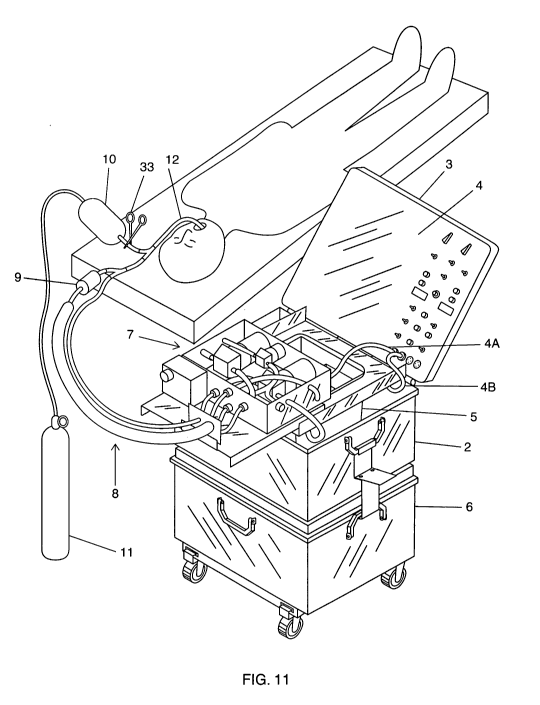
[0043] FIG. 11 illustrates portable heat exchange apparatus 1 in its fully
assembled condition with endotracheal tube 12 inserted into the lungs of a
patient. Portable heat exchange apparatus 1 is assembled by carrying out the
following steps: Infusion reservoir 21 is releasably connected to infusion
pump 51
by first connecting an end of an infusion tube 42B, having a quick release
female
fitting, to the quick release male fitting at the end of infusion tube 42A and
releasably connecting the other end of infusion tube 42B, also having a quick
release female fitting, to the quick release male fitting at the end of
infusion tube
42C. The biocompatible liquid tank 5 is releasably connected to suction pump
52
by connecting the quick release female fitting at the end of suction tube 40D
to
the quick release male fitting at the end of suction tube 40C. Next, ice water
14
CA 02700830 2010-03-25
WO 2009/042220 PCT/US2008/011224
container 2 is releasably connected to ice water jacket pump 53 by connecting
a
quick release female fitting at the end of supply tube 43A to the quick
release
male fitting at the end of supply tube 43B. Then, tube assembly 8 is
releasably
connected to each of the pumps within pump assembly 7. Quick release male
fitting at the end of infusion tube 42E is releasably connected to the quick
release
female fitting at the end of infusion 42D, quick release male fitting at the
end of
tube supply tube 43 E is releasably connected to the quick release female
fitting
at the end of supply tube 43D, quick release male fitting at the end of return
tube
44B is releasably connected to the quick release female fitting at the end of
return tube 44A, and the quick release male fitting at the end of suction tube
40A
is releasably connected to the quick release female fitting at the end of
suction
tube 40B. Clamp 33 is attached to tube 34, and electrical wiring connection 4A
is
plugged into a socket 99 (as shown in FIG. 12) within control panel 4 in order
to
supply power to pump assembly 7, and connection 4B is plugged into another
socket 98 (as also shown in FIG. 12) with in control panel 4 in order to
supply
power to the pumps and level sensors within ice water container 2,
biocompatible
liquid tank 5 and infusion reservoir 21. Finally, endotracheal tube 12 is
inserted
into the lungs of a patient.
[0044] All of the above-described electrical components are electronically
controlled by means of control switches on control panel 4 that are in
operable
connection to an electronic circuit and to either an external 12 volt direct
current
source or to an external 115 volt alternating current source. FIG. 12
illustrates
the various control panel switches and the schematic diagram presented in FIG.
13 illustrates the electrical circuit. Referring to both FIG. 12 and FIG. 13,
battery
packs 90A, 90B, and 90C and battery chargers 91 A, 91 B, and 91 C are disposed
behind control panel 4 and within lid 3 of ice water container 2. Control
panel 4
contains several toggle switches as follows: toggle switches S1, S2, and S3
control the supply of power to and from battery packs 90A, 90B, and 90C,
respectively; toggle switch S4 is a safety disconnect switch for the battery
packs;
toggle switch S5 allows for the selection of either the external direct
current
source or the internal battery pack power source; toggle switch S6 is an on-
off
CA 02700830 2010-03-25
WO 2009/042220 PCT/US2008/011224
switch for ice water pump 14 and return pump 24 (referred to as the "heat
exchanger pumps"); toggle switch S7 is an on-off switch for ice water jacket
pump 53; toggle switch S8 allows for the selection of either a manual or an
automatic mode of operation; toggle switch S9 allows for the manual operation
of
either infusion pump 51 or suction pump 52; and switch S10 is a pushbutton,
momentarily activated switch for priming and pre-cooling the biocompatible
liquid
before endotracheal tube 12 is connected to the patient as in FIG.11. Selector
dial 92 allows for the selection of an infusion cycle time, and selector dial
93
allows for the selection of a total infusion plus suction time. Ammeter 94 and
voltmeter 95 are digital displays of the operating current and voltage,
respectively.
Input sockets 96 and 97 are for external 12 volt direct current source or to
an
external 115 volt alternating current source, respectively. Output socket 98
is for
power output to the pumps and sensors within the ice water container 2,
biocompatible liquid tank 5 and reservoir 21, and output socket 99 is for
power to
the pumps within pump assembly 7.
[0045] FIG. 14 illustrates portable heat exchange apparatus 1 in a
transportable
configuration, comprising two similarly sized containers that have been
fastened
together. Ice water container 2 is positioned on top of storage container 6
and
the two containers are fastened together by using a pair of clamp assemblies
85,
with one assembly for each side of ice water container 2 and storage container
6.
The clamp assemblies 85 fasten ice water container 2 and storage container 6
together by utilizing a hooked member 86 at the end of each assembly, with the
hooked member clasping rotatable side handles 87 on each container. As
shown in FIG. 15A and 15B, each clamp assembly 85 can be released by
pressing down on flange 88, which in turn extends each clamp hooked member
86 in a downward direction, thereby permitting the removal of each clamp
assembly from its respective handles and the separation of the containers.
Clamp assemblies 85 are used to fasten the containers together by simply
reversing the process of releasing clamp assemblies 85. Connected to the
bottom of storage container 6 is a removable frame 89 with four wheels that
permit the containers to be transported by rolling them along the ground.
16
CA 02700830 2010-03-25
WO 2009/042220 PCT/US2008/011224
[0046] FIG. 16 illustrates ice water container 2 and storage container 6 after
they have been disconnected and further shows removable frame 89 after it has
been removed from storage container 6 and disassembled into two frame
segments. Disassembly of frame 89 permits it to be stored in storage container
6
by opening its hinged lid and placing the frame inside. Similarly, all of the
pumps
and tubes that deliver and return the biocompatible liquid to and from the
patient
can be stored in storage container 6. This is accomplished by disconnecting
each of the quick release fittings, removing pump assembly 7 from the top of
ice
water container 2, and then placing pump assembly 7 and tube assembly 8
inside of storage container 6.
[0047] Preferably, ice water container 2 and storage container 6 are both
Pelican brand transport cases, Model number 1620, fabricated from a
proprietary fiberglass-reinforced plastic blend and having interior dimensions
of
approximately 22"L x 17"W x 13"H, and exterior dimensions of approximately
25"L x 19'W x 14"H. These container dimensions allow for ice water container 2
and storage container 6 to be transported on commercial aircraft. For tubes
connected to heat exchanger 16, it is preferable to use 3/4" internal diameter
Shields mutiflex hose, and for tubes that may be clamped, it is preferred to
utilize 3/8 " internal diameter and 1/2" external diameter platinum cured
silicone
tubing. All other tubes can be Clearflex 60 transparent vinyl tubing, having
a
3/8" internal and 5/8" external diameter. Biocompatible liquid tank 5 is
preferably
a molded seamless polycarbonate container distributed by Master-Carr that is
about 1/8" thick and rated for a 12 quart capacity. Reservoir 21, pump
platform
13 and pump tray 14 are preferably made of 1/4 " ABS plastic. Preferably,
infusion pump 51 and suction pump 52 are FloJet , "Quiet Quad" automatic
multi-fixture pumps, model 4406-143, Type IV, 12 volt, 2.0 to 7.0 amp., 3.2
GPM,
and rated for a maximum pressure of 35 PSI; and ice water jacket pump 52 is a
FloJet , Type H, Model LF122202, 12 volt, 3.5 amp and rated for a maximum
flow rate of 1.1 GPM. The quick release fittings are preferably from Colder
Products Company, identified as model No. HFC12 polypropylene of 3/8" size,
and check valve 29 is a 1/2" ball check valve, part number 0050-BCTOO, from
17
CA 02700830 2010-03-25
WO 2009/042220 PCT/US2008/011224
Thermoplastic Valves. Heat exchanger 16 is preferably a Lytron LL510 heat
exchanger, manufactured by Lytron, Inc., and ice water pump 15 and return
pump 24, which are in connection with heat exchanger 16, are both submersible
centrifugal bilge pumps manufactured by Johnson Pumps of America (Model No.
L-650). Refill pump 22 is also submersible centrifugal bilge pump manufactured
by Johnson Pumps (Model No. L-450). Sensors 30, 68, and 69 are preferably all
polypropylene vertical-mount liquid-level switches, manufactured by Innovative
Components (Model No. LS-14-180). Endotracheal tube 12 is preferably a 9.0
mm I.D. diameter Rueschlit Super Safety, Armoured Tracheal Tube (#104004)
from Willy Ruesch AG in Germany. Filter 9 is preferably a "Terumo Capiox" 40-
micron arterial vented plastic bypass filter from Terumo Medical, Somerset,
N.J.
Air bag 10 can be a 2.6 L adult resuscitator hand-bag unit (07-870100) from
Laerdal Medical Corporation, New York, with a 1-way patient gas valve (07-
510112).
Preliminary Canine Experiments:
[0048] Extensive canine experiments were conducted by the inventors in order
to ascertain the most effective and safest manner in which canine core
temperatures could be reduced by cycling perfluorocarbon, as the biocompatible
liquid, into and out of the lungs. In these experiments it was demonstrated
that
lung lavage with cold perfluorocarbon transferred the maximal amount of heat
from the lungs of the animal on a timescale of at least as fast as the lavage
could
be administered and withdrawn, up to rates of at least 50 mL per kilogram of
canine body weight per minute. In these experiments no waiting time was
needed between the time the lavage was delivered into the lungs, and the time
it
was removed. It was also shown that only a fraction of the thermal content of
the
lavage, typically about 50%, equilibrated with the animal, but that this
fraction
was very little influenced by residence time in the lung, on a time scale of a
few
seconds to a few tens of seconds, which was typical of delivery and removal
time
of a lavage. For these reasons, it was thought that maximal heat transfer over
time took place without any residence time between the delivery and removal of
18
CA 02700830 2010-03-25
WO 2009/042220 PCT/US2008/011224
lavage volumes, with the lavage removed from the lung as quickly as possible
after being introduced.
[0049] These experiments, however, were done using a method which that did
not coordinate gas ventilation and liquid lavage. One reason for this was
because
of severe constraints in how fast lung lavage with perfluorocarbon could be
delivered and removed using the Prior Device described in the Background
section of this application. Also, it was also thought, incorrectly, that
lavage
volumes would be required to be several times the amount of mechanical dead
space in the dog respiratory system (i.e., several times 6 mL/kg) in order to
minimize the "thermal dead space" which was seen when small volumes of
perfluorocarbon (on the order of 9 mUkg or less) did not transfer heat as
efficiently as larger lavages (20 mL/kg). Only when a series of experiments
using
lavage volumes as small as 3 mUkg demonstrated a heat exchange that was
comparable to the higher lavage volumes per weight of the animal, was it
realized that proper coordination of lavage and gas ventilation could
effectively
transfer heat from smaller infusion volumes. The inventors believe that the
reason was due to an increased efficiency in liquid removal with the correct
type
of suctioning, coupled with turbulence in the delivered and removed liquid.
Such
turbulence corresponds, in terms of heat transfer, to the familiar elimination
of
dead space by "high frequency ventilation" or "panting" in the mechanics of
ventilatory mass (gas) transfer. In short, if the perfluorocarbon was
delivered to
and removed from the lungs quickly enough, a volume of liquid lavage was
required that was much smaller than anatomical dead space in the lungs.
[0050] At the same time, a number of ways of delivering gas ventilation to the
lungs were tried. As it was apparent that with the small volumes of
perfluorocarbon being used (as small as 3 mL/kg) that coordinated gas
ventilation (normally 10 mL/kg per breath) could and would supply most of the
gas exchange, then the key question was how to supply the quantity of lung gas
ventilation that would be required to keep the C02 levels in the animal's
blood at
normal levels. If the gas used was pure oxygen, it was found that CO2 removal
was the limiting factor in ventilation. CO2 removal is much more sensitive to
low
19
CA 02700830 2010-03-25
WO 2009/042220 PCT/US2008/011224
gas ventilation volumes than oxygen level in these circumstances, just as it
is
with total liquid ventilation. This occurs because at the low levels of C02 (4
to 5
% or 40 mmHg partial pressure) which occur in normal expired gas, the amount
of C02 in a volume of either gas or perfluorocarbon is always small, when
compared to the amount of oxygen contained in ventilatory gas or liquid if
100%
oxygen is used. We also found in a series of experiments that about 100
mUkg/min of gas ventilation per minute alone was needed to normalize
C02 in anesthetized 20-25 kg dogs. This could be delivered in as few as 4
breaths/min of 25 mL/kg for each breath, but slower rates required breath
volumes which resulted in unacceptable ventilatory pressures (>25 cm H20)
when liquid was present in the lungs. Also, we found that 100 mUkg/min of
gas(oxygen) ventilation was not quite sufficient to maintain normal pCO2
during
liquid ventilation, and pCO2 rose to 50 to 60 mmHg after 18 minutes of lavage,
even with small (3 mL/kg) lavages.
[0051] A series of coordinated experiments with 3 mL/kg perfluorocarbon
lavage and 25 mL/kg gas ventilation was initiated and found to give efficient
heat
transfer, but the relatively slow liquid lavage rate (3 mUkg x 4 lavages/min =
12
mL/kg/min) resulted in relatively slow rates of cooling of minus 0.25 C/min.
However, the rate of perfluorocarbon return available with the type of device
being used (not the presently described device) limited the lavage rate to 12
mL/kg/min for this size animal. In the MMLV patent and later publications the
inventors described cooling rates up to minus 0.5 C /min with larger lavage
rates
(liquid ventilation rates) up to 36 mUmin. However, this rate of lavage
required
relatively large infusions of 19 mUkg in order to take advantage of the rapid
return suction of infusion liquid which is possible when the liquid contains
few gas
bubbles (as happens with large lavage volumes). This is because liquid without
bubbles is easier to pump or suction. This rapid return was not possible with
Prior
Device with small lavage volumes, or with subsequent devices, until the
implementation of heat exchange apparatus 1 increased suction efficiency in
the
manner described in this application. Large lavage volumes of 20 mUkg as
described in the previous MMLV patent also required a relatively slow infusion
CA 02700830 2010-03-25
WO 2009/042220 PCT/US2008/011224
delivery due to the size of the lavage (1.6 lavages/min), and thus
discoordination
of lavage and gas ventilation in time.
[0052] With the availability of rapid lavage liquid suction in heat exchange
apparatus 1, it became possible to coordinate gas ventilation to lavage, but
also
to use relatively small lavages of 6 mL/kg with large amounts of gas (20 to 25
ml/kg), yet remove and infuse them sufficiently rapidly to perform 7.5
lavages/minute and 7.5 gas breaths per minute. This resulted in a liquid
lavage
rate of about 6 x 7.5 mL = 45 mUminute, and cooling rates of approximately 1
C/min. Since efficiency was maintained, the factor of 4 in lavage rate
resulted in
about the same factor of 4 improvement in cooling rate over the coordinated
breath/lavage dogs which received 12 mL/kg/min of perfluorocarbon. In
addition,
ability to perform 7.5 lavages per minute offered the opportunity of
performing 7.5
gas breaths of 500.mL per minute (3750 mL/min oxygen), which in a 25 kg dog is
150 mL//kg/min gas ventilation. This increase was enough to offset the
diffusion
barrier seen for C02 in liquid ventilation, and to result in normal levels of
C02 of
40-45 mmHg during liquid lavage.
[0053] With loss of the constraint of a minimal lavage volume needed for good
efficiency of heat transfer, it proved possible to coordinate smaller liquid
lavages
at effective breathing rates. At the same time, a series of experiments showed
that small lavages of perfluorocarbon fluid, of about the FRC in volume,
transferred heat maximally quickly, with the least increase in pressure and
the
least damage to the lung, when the lavages were administered as the lung was
being simultaneously inflated by a breathing gas, preferably with 100% oxygen,
as the lavage fluid was being introduced simultaneously. Less pressure was
required to inflate the lungs if the inflation volume was a mixture of gas and
liquid,
than if the volume was liquid alone, presumably because simultaneously
introduced gas is able to find, and recruit, non-dependent volumes of the lung
which are not accessed by the much heavier liquid. Furthermore, it was found
that heat transfer is more efficient in the dorsal recumbent dog than the dog
in
the lateral or ventral recumbent (prone) positions, presumably due to the
larger
21
CA 02700830 2010-03-25
WO 2009/042220 PCT/US2008/011224
surface area of dependent lung available to a heavy liquid, in a dorsally
recumbent animal.
[0054] A number of commercial perfluorocarbons were tried for these
experiments, and FluorinertT"' liquid FC-84 (perfluoroheptane) and
FluorinertT""
liquid FC-40 (perfluorotributylamine) from 3MT''" were both found to be
acceptable
liquids for use as the biocompatible liquid used in the experiments.
Commercial
PerflubronT"" is not suitable for liquid lavage at the liquid temperatures
used in
the experiments because it freezes at 4 C and is too viscous to be useable
below
150 C.
[0055] An additional series of experiments showed that delivery of cold
perfluorocarbon directly into the major tracheal branches of lung with small
(12 F)
catheters, followed by distal removal of liquid in from these catheters, or
even
distal infusion of fluid, followed by removal from a single catheter in the
upper
trachea, did not increase the efficiency of heat transfer of lavages. At net
rates of
lavage of 12 mL/kg/minute of perfluorocarbon (infusion rate 60 mL/kg/min,
fluid
suction rates up to 25 mL/kg/min), efficiency of heat exchange did not rise
above
60% (Abstract poster presented at Society for Critical Care Research meeting,
2002). However, these experiments did show that dogs could be cooled by -3 C
in less than 30 minutes. The relatively slow cooling rate in the above
experiments (0.1 C/min) could have been doubled by maximally chilling infused
perfluorocarbon to 1-2 C, but a further limit at 0.2 C/min was caused by the
relatively small rates of absolute suction which can be applied though small
tubes
(500 mL/min absolute). This contrasts with the 2 to 3 L/min suction which can
be
obtained for liquid from conventional flatwire venous drainage cannulae, such
as
the 17 F BiomedicusTM brand canulae used for surgical femoral artery bypass.
[0056] Furthermore, it was found that high speed jet delivery of cold
perfluorocarbon to the distal ends of the trachea caused evidence of damage,
as
hemorrhage was seen in the trachea on necropsy at 24 hours, corresponding to
the tip ends of the 12 French catheters. This damage disappeared when
perfluorocarbon was merely introduced into the upper end of the endotracheal
tube. In this case, to prevent perfluorocarbon overflow, the lung was merely
22
CA 02700830 2010-03-25
WO 2009/042220 PCT/US2008/011224
required to be inflated with oxygen gas ahead of the perfluorocarbon. When
this
was done, a flow of cold perfluorocarbon that was introduced into the top of
the
endotracheal tube dropped into the lungs and was further spread by an
insufflated breath of oxygen into the interior sections of lungs where heat
exchange took place.
[0057] In a similar fashion, attempts to minimize fluid dead space in the
lungs
by putting small suction catheters at the ends of the bronchi where not
ultimately
successful as methods of increasing net rate of heat transfer. This was, in
part,
due to the fact that the small diameter of the catheters limited the rate at
which
fluid could be removed from the lungs, and this limitation proved to further
limit
the rate of heat transfer, because it limited rate of liquid transfer.
Eventually, in
suction, it was found that the single greatest assistance to time-efficient
removal
of fluids from the lungs, and thus in time efficient transfer of heat, lay in
application of gentle negative pressure so that the lungs were collapsed, as
at
the end of a forced exhalation. This made maximal fluid from the lungs
available,
as at the end of a squeezed sponge, and this fluid could be picked up at the
end
of a normal endotracheal tube, situated relatively high up in the trachea, and
carried out by suction.
[0058] In summary, the inventors realized that a device which introduced fluid
to
the top of an endotracheal tube at the same time a gas breath was applied, and
then removed both gas and liquid from the top of the tube while suction was
applied to the entire cuffed tube, adequately performed both the job of
administration and removal of liquid from the lungs. No second luminal tube,
as
in the Prior Device described in the Background section of this application,
was
needed. By this reasoning, and with significant empirical experimentation, a
time-efficient technique for maximal heat transfer from small lavages of
perfluorocarbon within the lung of a canine was eventually developed, and
implemented in portable heat exchange apparatus 1.
23
CA 02700830 2010-03-25
WO 2009/042220 PCT/US2008/011224
Use of Apparatus:
[0059] In test experiments with 5 canines, the portable heat exchange
apparatus 1 was used to successfully lower the core temperature of the dogs by
cycling a volume of 6.0 to 9.3 ml of perfluorocarbon per kilogram body weight
of
the animal into and out of the lungs of the animal at a cycle rate of 1 cycle
approximately every 8 seconds, with a delivery period of approximately 3.5
seconds and a removal period of approximately 4.5 seconds. Each test
experiment was carried out in accordance with the following procedure. If pump
assembly 7 and tube assembly 8 have not be connected to ice water container 2
and biocompatible liquid tank 5 but are stored in storage container 6, the
operator opens the lid to storage container 6 and removes the two assemblies
and pump tray 14 from container 6. In this regard, although tube assembly 8 as
identified in the figures includes endotracheal tube 12, the endotracheal tube
would be normally stored in a sterile container separately from the other
components of tube assembly 8. The operator then closes the lid, attaches
frame 89 to the underside of storage container 6, places ice water container 2
on
top of storage container 6, and secures the two containers with clamp
assemblies 89. The operator starts preparing apparatus 1 for use by adding
approximately 15 liters of water and 10 kilograms of ice to ice water
container 2,
and by adding 6 liters of a biocompatible liquid, which in all experiments was
perfluorocarbon, to biocompatible liquid tank 5. The operator then starts
cooling
the perfluorocarbon in tank 5 by supplying power to the heat exchanger pumps
by connecting wiring 4A to socket 99 and connecting wiring 4B to socket 98,
and
then turning on heat exchanger pumps switch S6 on control panel 4, which
activates ice water pump 15 and return pump 24. This causes ice water to flow
from ice water pump 15, through tube 17A, through heat exchanger 16 where the
temperature of the ice water increases due to heat exchange, through tube 17B,
and out of sprayer 18, which returns the warmed ice water to ice water
container
2. Sprayer 18 diffuses the returning warmed ice water in order to increase the
efficiency of re-cooling the warmed ice water by distributing the warmed ice
water
over the surface of the ice cubes and ice water 19 in ice water container 2.
At
24
CA 02700830 2010-03-25
WO 2009/042220 PCT/US2008/011224
the same time, perFluorocarbon flows from return pump 24, through tubes 41 A
and 41 B, through heat exchanger 16 where the temperature of the
perfluorocarbon is reduced due to the transfer of heat between the
perfluorocarbon and the ice water, through tube 41 C and out of an open end of
tube 41 D which returns the cooled perfluorocarbon to tank 5.
[0060] While the perfluorocarbon is being cooled, the operator places pump
assembly 7 upon pump tray 14, which in turn is placed upon the top of ice
water
container 2 and connects the pumps within pump assembly 7 to biocompatible
liquid tank 5, as described above, and the operator connects tube assembly 8
to
pump assembly 7, as also described above. Next, the operator turns on switch
S7, activating ice water jacket pump 53, causing ice water to be delivered to
tube
assembly 8 by passing through supply tube 43A within ice water supply
assembly 80, through ice water supply tubes 43B, 43C, 43D, within pump
assembly 7, and through ice water supply tube 43E within tube assembly 8. The
ice water returns from tube assembly 8 by passing though return tubes 44B and
44A and into ice water container 2. At this point, an anesthetized dog that
has
been placed on an operating table next to apparatus 1 is intubated using
endotracheal tube 12. While the dog is being intubated, another operator uses
control panel 4 to set infusion/suction cycles. Based upon extensive
preliminary
testing described above it has been determined that apparatus 1 is capable of
delivering and removing a volume of perfluorocarbon to and from the lungs of
the
dogs weighing up to 27.5 kilograms at a rate of 1 cycle or lavage
approximately
every 8 seconds, with an infusion time period of approximately 3.5 seconds and
a suction time period of approximately 4.5 seconds. As a result, the operator
would normally use rotary switch 92 on control panel 4 to set the total
perfluorocarbon infusion time at 3.5 seconds, representing the elapsed time
between when infusion pump 51 starts delivering cooled perfluorocarbon to the
lungs and when the pump stops delivering perfluorocarbon. Next, using rotary
switch 93, the total cycle time of 8 seconds is set, which is equal to the
total
infusion time, plus the elapsed time between when suction pump 52 starts
removing warmed perfluorocarbon from the lungs and when the pump stops
2s
CA 02700830 2010-03-25
WO 2009/042220 PCT/US2008/011224
removing perfluorocarbon. Next, the operator establishes the desired volume of
perfluorocarbon that is to be delivered to the lungs during each infusion
cycle.
This is accomplished by adding or removing an appropriate number of volume
displacement tabs 60 to infusion reservoir 21. The tabs 60 are sized in
various
thicknesses so as to displace a wide range of fixed volumes of liquid in
reservoir
21. As set forth in the following table, reservoir 21 and tabs 60 are sized
such
that the following biocompatible liquid volumes can be added to tank 5 and
delivered to the lungs on each infusion cycle:
To deliver Insert tabs having these thicknesses:
this infusion
volume: 2" 1" 1/2" 1/4" 1/8"
110 ml yes yes yes yes yes
125 ml yes yes yes yes no
145 ml yes yes yes no yes
160 ml yes yes yes no no
180 ml yes yes no yes yes
195 ml yes yes no yes no
215 ml yes yes no no yes
230 ml yes yes no no no
300 ml yes no yes no no
370 ml yes no no no no
510 ml no yes no no no
650 ml no no no no no
In this regard, it has been determined by the inventors that based upon
extensive
preliminary testing that the most effective volume of perfluorocarbon at the
cycle
rate describe above is between about 6 and 9 mUkg of animal body weight. As
a result, the operator would first determine the weight of the animal and then
select the number of tabs that would deliver the appropriate volume of
perfluorocarbon. If an infusion volume below 400 mL is used, the operator
should
partially tighten screw-clamp 35 to constrain the flow of liquid from refill
pump 22
via tube 28 to reservoir 21. Constraining the flow is desirable to prevent
surging
of liquid in reservoir 21 when its effective volume has been decreased by
adding
displacement tabs. Surging of liquid causes inaccurate behavior of high-level
float sensor 67.
26
CA 02700830 2010-03-25
WO 2009/042220 PCT/US2008/011224
[0061] As soon as these preparations are completed and the dog has been
instrumented to record temperature and other experimental data, the operator
turns switch S8 to its manual position and primes the system by using switch 9
to
pump liquid through infusion tubes 42A, 42B and 42C, infusion pump 51,
infusion
tubes 42 D and 42E, and "Y" fitting 46, and into a graduated cylinder. The
operator then uses switch 9 to suction liquid back from the cylinder, through
suction tubes 40A and 40B, suction pump 52, and suction tubes 40C and 40D,
and repeats these cycles until all tubing in the system is fully loaded with
liquid.
"Y" fitting 46 is then attached to the open end of endotracheal tube 12 which
is
protruding from the animal's mouth.
[0062] The transfer of liquid from biocompatible liquid tank 5 into the tubing
of
the apparatus may result in liquid level 20 in tank 5 falling below its
minimum
acceptable level, in which case tank level sensor 30 will cause an alarm to
sound,
and the operator must add more liquid to tank 5 until the alarm stops
sounding.
[0063] Heat exchange is started by using switch S8 to select auto mode which
automatically starts continuously cycling the cooled perfluorocarbon into and
out
of the animal's lungs. During each suction cycle refill pump 22 is activated
and
replenishes reservoir 21 with cooled perfluorocarbon liquid. Pump 22 is
automatically turned off when the rising level of perfluorocarbon in reservoir
21
activates upper level float sensor 67. At the end of each suction cycle,
infusion
pump 51 is activated and cooled perfluorocarbon flows out of reservoir 21,
through infusion tubes 41A though 42E , through filter 9, through tubular "Y"
fittings 45 and 46, and through endotracheal tube 12 and into the lungs. Just
prior to each infusion of perfluorocarbon, however, the operator relaxes clamp
33
attached to tube 34 that opens and airway leading from air bag 10 to the lungs
of
the animal, and the operator begins to gently compress the bag with his or her
hands, thereby supply a breath of oxygen to the lungs as the perfluorocarbon
is
being infused. This action causes oxygen to mix to some degree with the
perfluorocarbon within endotracheal tube 12, and additional mixing occurs when
the perfluorocarbon and oxygen enter the lungs. Although it is preferable for
the
27
CA 02700830 2010-03-25
WO 2009/042220 PCT/US2008/011224
operator to use air bag 10 to deliver a breath of oxygen to the lungs at the
same
time that the perfluorocarbon begins to be delivered to the lungs, the
operator
has complete control over when and how much air is delivered and can depart
from the preferred procedure when, for example, the operator senses with his
or
her hands that too much pressure has built up in the lungs. Higher pressure in
the lungs can occur when, for what ever reason, a leak within the tubing or
the
tubular connection to the endotracheal tube reduces the amount of
perfluorocarbon that is removed from the lungs. As soon as infusion pump 51 is
turned off and perfluorocarbon stops flowing into the lungs, suction pump 52
is
again activated and the perfluorocarbon that has been warmed in the lungs is
removed from the lungs and it flows back through endotracheal 12 and tubular
fittings 46 and 45 and then through suction tubes 40A through 40D, where the
perfluorocarbon cascades down from an end of tube 40D until it reaches the
level
20 of perfluorocarbon in tank 5, above the opening in inlet pipe 26. As
described
above in connection with FIG. 9, the returning warm perfluorocarbon liquid is
directed into pump manifold 23, which re-circulates the liquid through the
heat
exchanger 16 and returns the liquid to tank 5, where it mixes with the
perfluorocarbon in tank 5. The delivery and removal cycles are continuous
cycles in that there is not any significant delay between each delivery of the
perfluorocarbon and its removal and the start of the next cycle. While heat
exchange is proceeding, high-level float sensor 67 will shut off refill pump
22
when the predetermined volume of perfluorocarbon has been delivered to
infusion reservoir 21, and low-level sensor 68 will stop the infusion pump if
the
desired volume has been infused in a shorter time than was set by rotary
switch
92. Further, after a significant amount of the ice in ice water container 2
has
melted, which can be readily observed by the operator, more ice can be easy
added to ice water tank 2 while heat exchange is proceeding. This is carried
out
by first draining some of the water from ice water container 2 by using a
drain
tube connected to quick disconnect 43F and then manually adding more ice to
the container.
28
CA 02700830 2010-03-25
WO 2009/042220 PCT/US2008/011224
[0064] FIG.'s 17 and 18 presented the cooling rates over time that were
achieved using heat exchange apparatus 1 to administer cold perfluorocarbon to
the five dogs using the procedure outlined above. Again, all experiments were
carried out by delivering perfluorocarbon at a cycle rate of 1 cycle
approximately
every 8 seconds, with the perfluorocarbon being delivered within approximately
3.5 seconds and being removed within approximately 4.5 seconds. Referring
first to FIG. 17, the figure presents a graph of cooling rates, in which
perfluorocarbon was continuously cycled into and out of the lungs of a 23 kg
dog.
A total of 40 cycles were administered over a heat exchange period of 320
seconds, when heat exchange was terminated. One line on the graph, labeled
"tympanic Temperature", illustrates that the dog's brain temperature, as
measured tympanically, dropped about 4 C within the 320 second period during
which heat exchange was administered to the animal. Another line on the graph,
labeled "Venous Blood Temperature", shows that the animal's venous blood
temperature was reduced by almost 6 C within the same time period. A third
line,
labeled "Arterial Blood Temp", shows a drop in temperature in which the
arterial
blood temperature was reduced approximately 8 C within the heat exchange
period.
[0065] FIG. 18 presents a graph of tympanically measured brain temperature
cooing rates for four canines, in which perfluorocarbon was continuously
cycled
into and out of the lungs of the dogs, again at a cycle rate of 1 cycle
approximately every 8 seconds, with the perfluorocarbon being delivered within
approximately 3.5 seconds and being removed within approximately 4.5 seconds.
A 23.3 kg dog received 6 ml of perfluorocarbon per kilogram of dog body weight
or a total of about 140 ml of perfluorocarbon per infusion cycle, and the
perfluorocarbon was continuously cycled into and out of the lungs over a
period
of 10 minutes. A 20.0 kg dog received 6.5 ml of perfluorocarbon per kilogram
of
dog body weight or a total of 130 ml of perfluorocarbon per infusion cycle,
and
the perfluorocarbon was continuously cycled into and out of the lungs over a
period of 10 minutes. 27.5 kg dog received 6.0 ml of perfluorocarbon per
kilogram of dog body weight or a total of 165 ml of perfluorocarbon per
infusion
29
CA 02700830 2010-03-25
WO 2009/042220 PCT/US2008/011224
cycle, and the perfluorocarbon was continuously cycled into and out of the
lungs
over a period of 15 minutes. And, a 20.4 kg dog received 9.3 ml of
perfluorocarbon per kilogram of dog body weight or a total of about 190 ml of
perfluorocarbon per infusion cycle, and the perfluorocarbon was continuously
cycled into and out of the lungs over a period of 15 minutes. The two dogs
that
both received lung lavages for 10 minutes exhibited a drop in brain
temperature
of approximately 8 C or about twice the total cooling exhibited by the dog
that
received lung lavage for just over 5 minutes as shown in FIG. 17. The 27.5 kg
dog that received lung lavages for 15 minutes exhibited a drop in brain
temperature of approximately 9 C, and the
20.4 kg animal showed a brain temperature drop of almost 11 C. These results
show that cooling rates are approximately constant for the first 10 minutes
but
then start to significantly slow down for longer time intervals.
[0066] In all of the animals, after heat exchange was terminated the animals
were allowed to thermally equilibrate for a period of time, and then
temperature
and pressure cannulae were removed from their arteries and veins, their
incisions closed, and they were removed from anesthesia. The endotracheal
tubes were removed as soon as the animals started breathing normally on room
air. Typical blood gases on room air resulted in p02 of about 250 mmHg on 90%
oxygen post lavage (about 450 to 500 mmHg pre-lavage) and normal pCO2 in
the 40 mmHg range. Post lavage oxygen on air was typically 70 mmHg, for an
increased A-a gap of about 30 mmHg. Saturation was typically >90 % on room
air (tongue pulse oxymetry).
[0067] Abnormality of breath sounds post lavage usually consisted only of
expiratory breath sounds in all lobes, approximating that of inspiration
(i.e., mild
obstruction, in as much as expiration was no longer quiet). Some dogs had mild
increases in expiratory time, and diaphragmatic breathing. However, all
animals
were up and walking, eating and drinking by the following day ("day two").
They
also showed no signs of abnormal behavior on day two. Lung sounds in some
animals normalized on day two, but other animals continued to show mild
obstructive sounds, without gross wheezing. Chest X-rays showed a very mild
CA 02700830 2010-03-25
WO 2009/042220 PCT/US2008/011224
alveolar diffuse infiltrate pattern immediately post-lavage with
perfluorocarbon
FC-84, which was gone at day two. The mild infiltrate pattern with
perfluorocarbon FC-40 persisted at day two. No pneumothorax or fluorothorax
was seen.
[0068] Three of the five animals were euthanized at 48 hours for lung
examination, blood gasses had not changed significantly. The animals were
anesthetized, perfused with saline, then formaldehyde fixative to replace
blood.
Lungs, when removed, showed a few petechial hemorrhages, but no major
damage or hemorrhage, and excellent washout of blood. When fully inflated by
endotracheal tube, they had no tears or leaks of air. Retained perfluorocarbon
was seen as a slightly yellowish discoloration in lung dependent lobes,
against
the white of normal lung. When lungs were fully inflated, this discoloration
tended
to be overridden by the lightness caused by air expansion of lung. The other
two
animals are still alive a about year after the experiments, and they have not
exhibited any noticeable side effects from the procedure.
Emergency Use:
[0069] In addition to the veterinary use described above, portable heat
exchange apparatus 1 can also be used to reduce the body temperature of
humans. It is known that the size of human lungs is approximately 75% the size
of canine lungs for the same body mass. Using this scale, it is anticipated
that
infusion volumes of approximately 6 mL/kg of human body weight (representing
about 1/3 of the functional residual capacity (FRC) within a human lung) and
cycle rates of 1 cycle approximately every 8.0 seconds would be safe and
effective. In this regard, it is anticipated that the most useful application
of
portable heat exchange apparatus 1 to humans would be in an emergency
situation where it is critical to safely reduce a patient's body temperature
as
quickly as possible. Accordingly, portable heat exchange apparatus 1 can be
used by paramedics or other emergency personnel to transport apparatus 1 by
ambulance to the location of a patient who is, for example, suffering from
cardiac
arrest and to quickly and efficiently administer heat exchange to the
patient's
31
CA 02700830 2010-03-25
WO 2009/042220 PCT/US2008/011224
lungs as soon as the emergency personnel arrive at the scene and have
restarted the heart, and while the patient is being transported by ambulance
to a
medical facility. Altematively, the apparatus 1 can be transported by aircraft
or
helicopter to a remote location, such a forest fire site or a war zone, where
it is
anticipated that the apparatus 1 may be needed by patients suffering from heat
stroke and who are too far away from a medical facility with skilled and
licensed
physicians having access to more elaborate and sophisticated equipment and
services. Further, apparatus 1 has a cryogenics application in that it can be
used
to reduce the temperature of a person's body until it can be cryogenically
preserved.
[0070] In the ambulance deployment scenario, the portable heat exchange
apparatus 1, in its transportable configuration as shown in FIG. 11, is
wheeled
into the ambulance as soon as the paramedics are notified of, for example, a
case of cardiac arrest. During transit to the patient's location, the
paramedics
disconnect storage container 6 from ice container 2 and remove pump assembly
7 and tube assembly 8, including its endotracheal tube 12, from the storage
container and connect assemblies to ice container 2 and reservoir tank 5. The
paramedics then begin preparing the apparatus 1 just as described above for
its
use with canines by adding approximately 15 liters of water and 10 kilograms
of
ice to ice water container 2, and by adding 6 liters of perfluorocarbon to
biocompatible liquid tank 5. Then they start cooling the perfluorocarbon in
tank 5
by turning on switch S7 to activate ice water pump 53 and turning of switch S6
to
activate ice water pump 15 and return pump 24. In addition, if the paramedics
have time before reaching the patient, they would prime the system in order to
remove air in the tubing. The priming operation is performed by first clamping
tube 47 so as to prevent the biocompatible liquid coming from reservoir 21 to
flow
out of "Y" fitting 46, thereby creating a closed system. Switch S8 is placed
in
manual mode and then switch S10 is pressed down for about 30 seconds,
causing the biocompatible liquid to cycle through the closed system, rather
than
to the patient. In this priming mode, infusion pump 51 and suction pump 52
both
run continuously in order to remove the air as fast as possible, and refill
pump 22
32
CA 02700830 2010-03-25
WO 2009/042220 PCT/US2008/011224
runs continuously in order to maintain the level of biocompatible liquid in
reservoir 21. Priming is stopped by releasing Switch S10 and returning switch
S8 to is off or center position. Alternatively, the paramedics can prime the
system
when they reach the patient, or in an extreme emergency start heat exchange
without priming the system.
[0071] When the ambulance reaches the patient, the portable heat exchange
apparatus 1 is wheeled on a ramp out of the ambulance and rolled into position
next to the patient, who is placed on a gurney and intubated by a paramedic
using endotracheal tube 12, which is then connected to "Y" fitting 46. While
the
patient is being intubated, another paramedic uses control panel 4 to set
infusion/suction cycles, which preferably would be the same as those cycles
described in the canine experiments. At this point, the paramedics are
required
to estimate the weight of the patient, which is an essential skill of all
licensed
paramedics. Once the patient's weight is estimated, the paramedic uses volume
displacement tabs 60 in order to establish the perfluorocarbon infusion
volume.
This is accomplished by adding or removing an appropriate number of volume
displacement tabs 60 to infusion reservoir 21. Tabs 60 are sized in various
thicknesses so as to displace a fixed volume of liquid in infusion reservoir
21.
More specifically, tabs 60 are sized such that for a given patient's
bodyweight
either a small, medium, large and /or extra-large displacement tab 60 is
positioned in infusion reservoir 21. If the patient weighs 108 kilograms or
more,
no displacement tabs are used. The following table presents several
displacement tab combinations to deliver a fixed volume of perFluorocarbon to
a
patient based upon the delivery of 6.0 mL/kg of perfluorocarbon per body
weight
of the patient:
Patient Include these tabs:
Weight:
small medium large x-large
108 kg (or more) no no no no
102 kg yes no no no
96 kg no yes no no
33
CA 02700830 2010-03-25
WO 2009/042220 PCT/US2008/011224
90 kg yes yes no no
84 kg no no yes no
78 kg yes no yes no
72 kg no yes yes no
66 kg yes yes yes no
60 kg no no no yes
54 kg yes no no yes
48 kg no yes no yes
42 kg yes yes no yes
36 kg no no yes yes
30 kg yes no yes yes
24 kg no yes yes yes
18 kg yes yes yes yes
For example, for a patient weighing 54 kg a small and extra-large sized tab
would
be disposed within infusion reservoir 21, which would result in delivering 324
ml
to the lungs of the patient on each infusion cycle.
[0072] As soon as these preparations are completed, heat exchange is started
by unclamping tube 47and using switch S8 to select auto mode which
automatically starts cycling the cooled perfluorocarbon into and out of the
patient's lungs, and the apparatus operates just as described in the canine
experiments. As soon as heat exchange has been started, the patient and the
portable heat exchange apparatus 1 are rolled in tandem back to the ambulance
where the heat exchange and liquid ventilation can be continued until the
patient
is delivered to a medical facility. At that point, heat exchange can be
continued
with heat exchange apparatus 1 or it can be quickly disconnected and more
sophisticated equipment and procedures can be used to cool down the patient's
body temperature.
[0073] In the second scenario, heat exchange apparatus is delivered by air
carrier to a location where it is anticipated that it might be needed. Once at
the
location, the apparatus can be assembled and easily wheeled into position,
just
as it is when removed from an ambulance, and then used in the same manner. It
is anticipated that under this scenario the apparatus would be the procedure
of
last resort due to the remote location of its use. However, it is feasible
that the
patient could be transported by air while continuing to receive heat exchange
therapy, just as in an ambulance scenario.
34
CA 02700830 2010-03-25
WO 2009/042220 PCT/US2008/011224
[0074] In addition to performing heat exchange within the lungs of patients,
the
apparatus 1 is intended for use immediately after death is pronounced to cool
the
person's brain and body, thus lowering the metabolic rate and reducing
ischemic
injury until the person can be cryogenically preserved. In this instance, the
apparatus is used in the same manner as that described for a living patient;
however, the apparatus could be used for much longer periods of time during
which the body temperature could be lowered far below the level that would be
safe for a living patient.
Thermal calculations:
[0075] The size of individual lavages was dictated in part by how much fluid
could be delivered and removed at a rate or breathing cycle of 1 cycle
approximately every 8 seconds, which was the gas ventilation rate calculated
to
keep pCO2 in the normal range in arterial blood of the animals. In this
regard,
oxygen saturation was typically much higher, around 250 Torr, due to the 100%
oxygen gas used to ventilate. The primary limitation on lavage total rate was
the
amount of fluid suction that could be accomplished in the suction part of the
breathing cycle, which was approximately 4.5 seconds.
[0076] In summary, the perfluorocarbon volumes described herein represent
reasonable limits as to amounts of liquid which can be added and removed from
the lungs of a mammal, in a normal ventilation cycle time of about 7.5 lavages
per minute. As discussed below, this amount of fluid (56 to 72 mUkg/min) is
also
that which is required to obtain about a 4 C temperature drop in the brain in
the
first 5 minutes of post resuscitation lung lavage with ice cold
perfluorocarbon.
Calculations of Heat Transfer:
[0077] The total heat capacity of mammals is about 0.7 kcal/kg/degree K. In a
situation of very rapid cooling, as when done with MMLV lung lavage, only
about
60% to 70% of the heat capacity (the so-called thermal core) of the animal is
cooled , and this is responsible for the 30%-40% "rebound re-warming" which
occurs after rapid cooling has stopped. This can be prevented by "overcooling"
CA 02700830 2010-03-25
WO 2009/042220 PCT/US2008/011224
by 30% to 40% in the active phase of cooling. In lung lavage medical devices,
a
reasonable goal has been to cool the brain by minus 4 C in the first 5
minutes of
treatment. It has been argued by Dr. Lance Becker (University of Pennsylvania)
that this cooling rate is necessary for maximal effect, since minus 40 C has
been
the traditional amount of cooling to induce "mild hypothermia" with its many
benefits in post-resuscitation, and 5 minutes is the maximal time in which the
brain can survive without the beginning of ischemic damage, in the absence of
blood pressure. Dr. Becker has argued that induction of mild hypothermia in
this
time period would provide the best chance to induce the favorable state in a
time
which would not be so long as to allow much ischemic damage in the post-
resuscitation period.
[0078] During such a treatment which aims to drop brain temperature by minus
4 C in 5 minutes, the maximal cooling rate needs to rise to about 1.2 degrees
C/min, in order to compensate for the fact that during the first 60 seconds of
blood-cooling there is little temperature drop in the brain due to blood
convection
delay time, and it requires about 100 seconds for maximal rate of temperature
drop (dT/dt) in the brain to become fully developed, after the start of rapid
removal of heat from the lungs. The treatment need not be continued longer
than 5 minutes if a permanent decrease in whole-body temperatures of minus 4
C is desired, since the nadir of cooling is not reached until about 1 minute
after
cooling stops, and is lower than the target. After 5 minutes of treatment,
then
cessation of cooling, core temperature continues to drop between minus 5 to
5.5
C at 5.9 to 6.6 minutes after the start of treatment, then rises again as the
thermal compartments of the animal all equilibrate. A permanent temperature
drop of about minus 4 C may be expected once this equilibration has happened.
In experiments to be presented, a wait of up to 30 minutes (1800 seconds) has
been instituted to observe this equilibration after 5 to 15 minutes of lung
lavage.
Equations:
[0079] The total volume of perfluorocarbon per mass of animal (volume/mass)
required to cool a mammal by a permanent temperature drop (ATm) of minus
36
CA 02700830 2010-03-25
WO 2009/042220 PCT/US2008/011224
4 C is calculated by equating the heat added to the perfluorocarbon volume
(Vf),
to the heat removed from the animal. This heat (Q) is the total
perfluorocarbon
volume (Vf) multiplied by the volume specific perfluorocarbon heat capacity
(Cv),
multiplied by the difference in temperature between this perfluorocarbon
volume
and the mammal, ATf, multiplied by the efficiency E with which the heat is
extracted from the perfluorocarbon in the process. This heat, given by the
formula Q = Vf * Cv* ATf "E, is the heat gained by the perfluorocarbon. It is
equal
to the heat lost by the mammal, which is given by the mass-specific heat
capacity
of the mammal (Cm) multiplied by mammal mass m and the temperature change
in the mammal. This heat lost by the mammal is given by
Q=mCm*ATm.
[0080] Equating the two heats and solving for Vf/m (the volume of
perfluorocarbon needed per kg of mammal) gives:
Vf/m = [ATm/ATf]'' [Cm/Cv] * [1/*E] Eq 1.
where the mean temperature difference between the perfluorocarbon and animal
(ATf) is 33 C and the temperature change in the mammal (ATm) is 4 C;
the mass-specific heat capacity of the whole mammal (Cm) is about 0.7 Kcal/kg
(as shown by many experiments with various lean mammals, all showing
approximately this heat capacity); and the volumetric heat capacity (Cv) of
all
perfluorocarbon liquids is about 0.45 Kcal/L.
[0081] The efficiency for heat transfer (E) from perfluorocarbon to mammal is
a
pure number which represents the amount of heat the perfluorocarbon absorbs in
practice, with regard to the theoretical maximal amount it could extract in
theory.
An efficiency of 1 (100%) would mean perfluorocarbon would return from the
animal at the brain temperature of the animal, having come to perfect
equilibrium
with it before being extracted. In practice, efficiency numbers for small lung
lavage models with the lavage properly placed, are nearly always 50 to 60%.
[0082] In our dog model , the median thermal efficiency of small
perfluorocarbon lavages has been found to be about 60% for rapid lavage and
this is relatively independent of the size of the lavage. This probably
represents
the fact that lavage perfluorocarbon returns at a temperature which is set by
the
37
CA 02700830 2010-03-25
WO 2009/042220 PCT/US2008/011224
venous and arterial blood, which are minus 2.5 and 5 C lower than the brain,
respectively, and also by the fact that newly delivered perfluorocarbon drops
into
a "pool" of warm perfluorocarbon already in the lung, and also contacts
regions
of lung which cannot efficiently transfer heat to it. Both of these effects
result in a
kind of thermal dead space, which is represented by a volume of V(1-E) where V
is the volume of infusion, and E is the efficiency.
[0083] Using these numbers the total amount of perfluorocarbon V to give a
minus 4 C permanent temperature drop (AT) is:
V = (4/33) * (0.65 kcal/kg/K / 0.45 kcal/UK) * (1/0.60) = 0.314 L/kg = 290
mUkg,
representing the amount of perFluorocarbon that will cool the animal
permanently
by minus 4 C, whether it is cyclically infused and removed during 5 minutes,
30
minutes, or longer. If this volume is to be given in 5 minutes at a rate of
7.5
lavages per minute, then it must be divided into 37.5 lavages, with each
lavage
composed of 314/37.5 = 7.8 mL/kg lavage. This is a lavage rate of 58
mL/kg/min.
[0084] In order to achieve cooling of minus 4 C in the first 5 minutes of
lavage,
a maximal heat transfer of 1.1 C/min must be created, largely to compensate
for
the relative lack of transfer in the first 1 minute of the experiment.
However, this
rate of cooling must be achieved only for the thermal "core." These are the
tissues which are very well perfused tissues, such as the lungs heart,
viscera,
and brain. They represent a thermal capacity corresponding to only about 68%
of
the heat capacity of the mammal, or about 0.47 kcal/kg/K. Thus, the maximal
cooling rate (cooling only the animal core) is given by solving equation 1
above
for ATm:
ATm = V ATf [Cv/Cm] E.
Differentiating this equation (dV/dt) gives the cooling rate expected for
given a
rate of lavage:
dTm/dt = [Cv/Cm] * E* (ATf ) dV/dt.
Using Cm = 0.47 kcal/kg/K in this calculation because of the smaller thermal
(core) mass Cm being cooled during the rapid phase of cooling (ie, the whole
body is not being cooled in the early phase, but only the thermal core
including
the brain), the rate of maximal brain cooling may be calculated.
38
CA 02700830 2010-03-25
WO 2009/042220 PCT/US2008/011224
A minute-lavage rate of dV/dt = 58 mUkg/min, then the total lavage rate dV/dt
per minute is given by:
dT/dt = [ 0.45/0.47] (0.6) * (33) * 0.058 Umin = 1.1 C/min
This is maximal cooling rate which may be expected at this lavage rate.
[0085] The needed total of about 290 mL/kg perfluorocarbon must be delivered
as 290/37.5 = 7.8 mUkg lavages if these are to be given within 5 minutes. This
should achieve a drop of minus 4 C at 5 minutes and a permanent drop of about
the same amount. However, the nadir of the temperature drop will be lower than
this figures, and can be estimated by the relative size of the temporarily
cooled
"core" thermal capacity to final thermal capacity, which two capacities which
have
a ratio of 0.7/0.45 = 1.55. Thus, the nadir in core temperature can be
expected to
reach 4 x 1.55 = minus 6.2 C in a short cooling time experiment in which
minus
4 C decrease in 5 minutes, and also minus 4 C permanent decrease, is the
final goal. A drop of 4.6 0 C against a final drop of minus 3.7 C was
actually
seen (ratio of 1.24). If smaller lavage size is used, the cooling rates in
theory will
be reduced proportionally. For example, if 6.1 mL lavages are used, as is the
mean lavage size 4 of 5 of the animals shown in figures 1 and 2, then cooling
rates and final amount of cooling might be expected to be 6.1/8.4 = 73%
expected in the calculation above. In the dog shown in figure 1, lavage at the
rate
of 45 mI/kg/min was performed, and maximal cooling rate of minus 0.92 C/min
was observed, as compared to 1.1 x 78% = minus 0.86 C/min expected. The
final temperature drop in this animal, which was lavaged for slightly longer
than 5
minutes (5.25 min) was minus 3.7 0 C. The total lavage delivered was 6 mUkg x
40 lavages = 240 mL/kg. The expected temperature drop was minus 4 C
(240/290) = 3.3 0 C against the drop of 3.7 C actually observed.
Advantages:
[0086] Using portable heat exchange apparatus 1 to reduce the core body
temperature of a mammal has several advantages over the Prior Device
disclosed in the MMLV patent. Most significantly, apparatus 1 has demonstrated
the ability to reduce core body temperature by about 4 C in approximately 5
39
CA 02700830 2010-03-25
WO 2009/042220 PCT/US2008/011224
minutes, which represents an increase in cooling rate during that time of
almost
300% over the Prior Device. Apparatus 1 has been able to achieve this
substantially increased cooling rate due to several unique design features
that
have been incorporated into the apparatus. One feature is that the
perfluorocarbon is delivered to the lungs of the mammal through a single
endotracheal tube in that the use by the Prior Device of a separate
infusion/suction tube concentrically disposed within its endotracheal tube has
been eliminated. This change has substantially increased the tubular cross-
sectional area for delivery of the perfluorocarbon, thus facilitating the
delivery of
much higher volumes of perfluorocarbon. This change has also provided for the
elimination of the oxygenator used in the Prior Device to remove CO2 from the
perfluorocarbon being removed from the lungs, because the Prior Device
delivered a volume of gas ventilation that was 2 to 3 time larger than the
volume
of the perfluorocarbon being delivered at the same time. This amount of gas
ventilation renders the amount of ventilation delivered and removed by the
dissolved gases in the lungs as inconsequential. In consequence, direct
oxygenation and C02 stripping of the perfluorocarbon liquid is not necessary
with
the relatively small lavage sizes (6 to 9 mL/kg) delivered with the relatively
large
gas breaths (mean of 21 mL oxygen/kg for this group with mean weight of 23
kg).
In addition, the perfluorocarbon being delivered to the lungs is substantially
cooler than the perfluorocarbon that was delivered by the Prior Device. This
additional cooling is provided by several other unique features. The Prior
Device
stored the perfluorocarbon in a container that was separated from an ice water
slurry and transferred the perfluorocarbon through tubing to the heat
exchanger.
The present apparatus disposes or nests biocompatible liquid tank 5, which
contains the biocompatible liquid, inside of ice water container 2, which
contains
ice water 19. In this manner, apparatus 1 is able to eliminate the long tubing
between the two containers as in the Prior Device and replaces the tubing with
much shorter tubes that are submerged in ice water 19. Submerging the tubing
in ice water 19 provides a superior insulator to the foam insulation used to
insulate the tubing in the Prior Device. Similarly, surrounding biocompatible
CA 02700830 2010-03-25
WO 2009/042220 PCT/US2008/011224
liquid tank 5 with ice water 19 also provides a much more effective manner of
keeping the biocompatible liquid cool, rather than using foam insulation as in
the
Prior Device. Another deficiency of the Prior Device is that it used only foam
insulation surrounding the long tubes that delivered the biocompatible liquid
from
its container to the lungs of the mammal. Apparatus 1, on the other hand,
circulates some of the ice water from ice water container 2 through tube
assembly 8, which further includes an insulation jacket assembly 36
surrounding
the tubing within the assembly. Again, the circulating ice water provides
substantially more insulation than only the foam used in the Prior Device.
[0087] In addition to the substantially improved heat exchange
characteristics,
apparatus 1 is portable and easy to use in an emergency. Portability is
provided,
in part, by the unique nesting of biocompatible tank 5 within ice water
container 2
and by the modular design of pump assembly 7 and tube assembly 8, which
greatly facilitate storage of the components in storage container 6 and the
ease
with which apparatus 1 can be assembled in an emergency. Mobility is provided
by mounting the ice water and storage containers on removable wheeled frame
89. Portability is further enhanced by eliminating the large, computer
controlled
ventilator use in the Prior Device with air bag 10 that is manually operated
to
supply oxygen to the mammal. In addition to being extremely light compared to
the computer controlled ventilator, manual operation allows the operator to
use
his or her hands to sense when the lungs are filled to capacity, thereby
avoiding
the potential that that lungs might be over inflated by the computer and
causing
severe damage to the lungs.
[0088] Although the portable heat exchange apparatus and method has been
described in its preferred embodiment and in certain other embodiments, it
will
be recognized by those skilled in the art that other embodiments and features
may be provided without departing from the underlying principals of those
embodiments. The scope of the invention is defined by the appended claims.
41