Note: Descriptions are shown in the official language in which they were submitted.
CA 02700847 2010-03-25
WO 2009/039659 PCT/CA2008/001716
COUNTERBALANCE ASSEMBLY
Field of the Invention
[0001] The present invention relates generally to counterbalances
and,
more particularly, to a counterbalance for a joint of a mechanical arm.
Backaround of the Invention
[0002] Apparatus comprising a mechanical arm that can hold and
guide a
payload have been shown to be of valuable assistance in various industrial
procedures or medical procedures, for example, manipulation of tools,
manipulation of cameras or sensors, etc.
[0003] These apparatus typically have one or more degrees of freedom
and may be manually driven in that the one or more degrees of freedom may be
equipped with a brake with motive force being provided by a human user, or
may be automated in that at least one degree of freedom is driven by a
computer controlled actuator.
[0004] A balancing mechanism may be used to counteract the force of
gravity for hinged and/or articulated arm. Elimination or reduction of the
effects
of gravity allow the use of smaller power sources, gears and/or less effort
exerted by a manual user. This is desirable from a cost standpoint and allows
for a more compact design which, in turn, allows greater accessibility to the
workspace.
[0005] Several counterbalancing mechanisms have been previously
disclosed, for example, US Patent No. 4,756,204, US Patent No. 4,546,233, or
US Patent No. 4,500,251.
[0006] Balancing mechanisms used on articulated arms and hinge
mechanisms include counterweights. However, the use of counterweights can
result in added mass and increase in arm inertia.
[0007] A tension spring or passive pneumatic balancer may be used
for
balancing within a small angle or within a single quadrant (i.e. from a
horizontal
to vertically upward orientation). However, conventional tension springs
typically
do not adequately balance the gravitational load. Also, it is inherent in most
spring balancing methods that complete balance is possible only for one or two
configurations of the arm and spring combination. As the robot arm moves away
CA 02700847 2015-09-16
,
- 2 -
from that configuration in either of two possible directions, an unbalance is
generated. Thus, a danger of this mechanism may be drifting or falling under
the force of gravity when actuation is removed or reduced. Therefore, such
mechanisms are usually provided with brakes to alleviate the potential danger,
or are overbalanced against gravity.
[0008] Compression springs operating on small moment arms may
overcome an angular limitation problem and offer better balance over the
entire
range of travel of the robot's arm. However, the problem of drift or falling
under
gravity also exists with compression springs.
[0009] It is an object of an aspect of the present invention to provide a
counterbalance assembly for a joint of a mechanical arm.
Summary of the Invention
[0009a] In an aspect, there is provided a counterbalance assembly
for a
rotatable mechanical arm comprising: a first force generating device
interacting with an associated first cam; and a second force generating device
interacting with an associated second cam, wherein the first and second cams
are fixed eccentrically relative to a pivot of a joint about which said
mechanical
arm rotates, said first force generating device and said second force
generating device are offset by 90 degrees, said first and second force
generating device are first and second springs, and the relationship of the
first
force generating device to the second force generating device and the first
cam to the second cam is preserved throughout rotation of the mechanical
arm.
CA 02700847 2010-03-25
WO 2009/039659
PCT/CA2008/001716
- 3 -
Brief Description of the Drawings
[0010] Embodiments will now be described, by way of example only,
with
reference to the attached Figures, wherein:
[0011] Figure la illustrates a dual spring counterbalance assembly
at a
joint of a mechanical arm using springs that are fixed to a ground and cams
set
eccentrically relative to the pivot of the joint;
[0012] Figure lb illustrates a variant of the counterbalance
assembly
shown in Figure la with a different orientation of springs and cams;
[0013] Figure lc illustrates a dual spring counterbalance assembly
having springs attached to the payload arm;
[0014] Figure Id illustrates a triple spring counterbalance
assembly with
an additional spring and an additional cam being added to the counterbalance
assembly shown in Figure 1 b;
[0015] Figure 1e illustrates a simplified variant of the
counterbalance
assembly shown in Figure Id with removal of a spring resulting in two springs
interacting with three cams;
[0016] Figure If illustrates a mechanical arm of the counterbalance
assembly shown in Figure 1d;spring/cam relationship in a spring balance
mechanism for a mechanical arm;
[0017] Figure lg is the same as Figure If except that the bolt head
extension of a spring is cut away to more clearly show two cams;
[0018] Figure 2a illustrates a cross-sectional view of a dual
spring
counterbalance assembly showing springs coupled to cams set eccentrically
relative to a pivot of a joint;
[0019] Figure 2b is a schematic diagram illustrating the geometric
relationship between each spring-cam assembly shown in Figure 2a;
[0020] Figure 3 illustrates a cross-sectional view of a mechanical
arm
comprising a variant of the spring balance mechanism shown in Figure 2;
[0021] Figure 4 illustrates the phase relationship between springs
and
cams in various configurations of mechanical arm rotation;
[0022] Figure 5 illustrates a variant to the design presented in
Figure 3;
and
SUBSTITUTE SHEET (RULE 26)
CA 02700847 2010-03-25
WO 2009/039659
PCT/CA2008/001716
- 4 -
[0023] Figure 6 illustrates an example of a medical guide apparatus
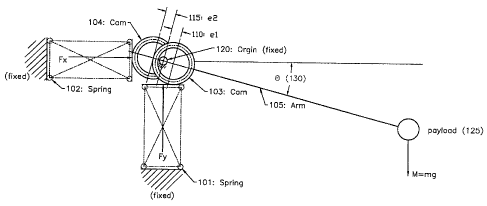
that
can comprise the spring balance mechanism shown in Figure 1.
Detailed Description
[0024] Figures 1 a to le are schematic illustrations of spring
counterbalance assemblies which show the geometric relationship of spring and
cams. Referring to Figure la and lb, the spring counterbalance assembly
comprises two compression springs (101, 102), each of which are fixed at the
base (or grounded fixture) and the other end(s) are connected to eccentric
circular cams(103, 104) by a yoke (not shown), such that each cam is free to
rotate about the fulcrum or pivot (120) of a joint, and the springs are free
to
compress (or stretch). The springs may be adjustable. Cam 103 is eccentrically
set relative to the pivot (120) of a joint by a distance equal to el (110),
and cam
104 is eccentrically set relative to the pivot (120) of the joint by a
distance of e2
(115).
[0025] Spring (101) interacts only with cam (103), and spring (102)
interacts with cam (104). Both of the cams are in turn pinned to the lever/arm
(105) that supports the payload (125). The compressive (or tensile) force
exerted by each spring results in a net torque being exerted about the pivot
(120) of the lever supporting the load.
[0026] Figures la and lb schematically illustrate different orientations of
springs and cams in a counterbalance assembly designed to fully support the
weight of a payload about a hinged connection which is connected to a ground
or stable fixture. The base of each spring is anchored to the ground (or
fixture)
while the lever/arm (105), pinned to the cams (103, 104) is free to rotate
about
the pivot (120) of a joint of a mechanical arm. The ability to establish
equilibrium
of torque relative to pivot (120) is not limited to specific spring-cam
orientations
shown in Figures la and lb as will be apparent from equilibrium equations
provided below.
[0027] In Figure la the relationship between spring (101) and cam
(103)
to the lever/arm supporting the load is orientated such that the line joining
the
pivot (120) and el (110) is not coincident with the line joining the pivot
(120) to
SUBSTITUTE SHEET (RULE 26)
CA 02700847 2010-03-25
WO 2009/039659 PCT/CA2008/001716
- 5 -
the center of gravity of the payload (125), which includes mass of the
lever/arm
(105). In an example of an alternate orientation shown in Figure lb the
relationship between spring (101) and cam (103) to the lever/arm supporting
the
load is orientated such that the line joining the pivot (120) and el (110) is
coincident with the line joining the pivot (120) to the center of gravity of
the
payload (125), which includes mass of the lever/arm (105). In both Figures 1 a
and lb the orientation of the spring/cam relationship is preserved throughout
rotation. Thus, if the cam is in a desired position with respect to the pivot,
that
will define the orientation of the spring in space. If the spring is in a
desired
position in space, that will define the position of the cam with respect to
the
pivot.
[0028] In the configuration shown in Figure lb, the orientation of
the cam
to the lever/arm constrains spring (101) to a vertical position. If the
eccentric
point is in between the pivot/fulcrum and center of gravity as shown in Figure
lb,
spring (101) will exert a compressive force in its current configuration to
offset
the payload when the arm is horizontal (theta (130) = 0 degrees). If the
pivot/fulcrum is in between eccentric point and center of gravity (not shown),
spring (101) will exert a tensile force to offset the weight of the payload.
The
user can initially set spring (101) such that its initial compression offsets
the
mass of the payload, for example when the arm is in the horizontal position
(le,
when the cam 103 is 90 degrees out of phase with spring 101).. The pre-
compression of spring (101) will typically be set with the arm (105) in the
horizontal position since the torque exerted by the arm is greatest at this
point.
However, pre-compression may also be set with the arm being above or below
horizontal by extrapolation.
[0029] In Figure lb, the relationship between spring (102) and cam
(104)
to the lever/arm supporting the load is orientated such that the line joining
the
pivot (120) and el (10) is coincident with the line joining the pivot (120) to
the
center of gravity of the payload (125), which includes mass of the lever/arm
(105). The orientation of the cam to the lever constrains spring (102) to a
horizontal position. If the eccentric point is in between the pivot and center
of
gravity (not shown), spring (102) will exert a tensile force in its current
SUBSTITUTE SHEET (RULE 26)
CA 02700847 2010-03-25
WO 2009/039659
PCT/CA2008/001716
- 6 -
configuration to offset the linear change in force of spring (101). If the
pivot
(120) is in between eccentric point and center of gravity as shown in Figure
lb,
spring (102) will exert a compressive force. In the specific example shown in
Figure lb, spring (102) is not adjustable, and is set by design such that the
spring exerts no load on cam (104) when the arm (105) is in a vertical
orientation (90 or 270 degrees relative to a Cartesian coordinate system where
0 degree corresponds to the positive X axis).
[0030] Still referring to Figure lb, the relationship between each
cam-
spring pair is such that each cam is 180 degrees out of phase with each other
(pivot (120) is in-between the eccentric points (110) and (115)). In this
configuration, each of the springs is constrained to be 90 degrees out of
phase
with each other (perpendicular). The relationship created from the constrained
relationship between each spring/cam pair is the torque exerted by spring
(101)
leads spring (102) by 90 degrees.
[0031] In an alternate embodiment, each spring/cam pair can be rotated
about the pivot (120) to any position (for example, springs are aligned, 0 or
180
degrees) as long as the relationship between the cam and corresponding spring
is maintained.
[0032] Thus, the ability to establish equilibrium relative to pivot
(120) is
not limited to specific spring-cam orientations shown in Figures 1 a and lb as
will
also be apparent from equilibrium equations provided in the following
paragraphs.
[0033] Alternatives to Figure 1 a and lb are shown in Figures 1 0-1
e.
Figure 1 c is an alternate embodiment of the mechanism illustrated in Figures
la
and lb where the springs are attached to the arm (105) and the cams are
attached to the ground (or fixture). Figure Id adds an additional spring (140)
and cam (145) to the spring/cam relationships shown in Figures 1 a and lb and
thus eliminates the need for spring (102) to exert both compressive and
tensile
loads. Spring (102) as shown in Figure 1 a and lb when coupled by a yoke to
cam (104) can be required to exert both tensile and compressive loads.
Addition of spring (140) and cam (145) shown under the cutaway portion of cam
(104) in Figure Id, allows the use of compression springs (102 and 140) that
SUBSTITUTE SHEET (RULE 26)
CA 02700847 2010-03-25
WO 2009/039659
PCT/CA2008/001716
- 7 -
abut their respective cams (104 and 145) and exert only compressive loads.
Figure le shows a further simplification of the assembly illustrated in Figure
1d
with spring 102 interacting with both cams (145 and 104). Cam 145 is shown
under the cutaway of cam (103). The assembly design shown in Figure 1d
allows for the use of compression spring (102) to abut cams and only exert a
compressive load, while removing the need for spring (140). The assembly
shown in Figure le can be even further simplified by setting spring (102) to
interact with both cams (103 and 104), thus removing the need for spring (140)
and cam (145). Figures If and 1g show the assembly design of Figure 1d as
implemented on a mechanical arm.
[0034] The following is a description of the equilibrium equations
that
govern the geometric spring/cam relationships shown in Figure la-le. The
force friction has been omitted from this analysis as it has no bearing on the
equilibrium equations when the machine is at rest. Friction can be used as an
advantage to construct inexpensive mechanisms that behave in a similar
manner to the case illustrated in Figure 1 but do not fully balance the load.
The
sum of all the frictional forces between every moving part within the
mechanism
would prevent drift.
[0035] Referring to figure 1a, equilibrium about the pivot (120) is
established when the net torque is zero, i.e.:
T +T +T =0
X y (1),
where Tg is the unbalanced torque due to the payload (125), and the
unbalanced torque produced from spring (101) and (102) are Tx and Ty
respectively. The unbalanced torque produced by the weight is the product of
the gravitational force due to the payload M, and the shortest distance
between the force vector (M=mg) and the point (120):
T = Mr coS(9) (2).
SUBSTITUTE SHEET (RULE 26)
CA 02700847 2010-03-25
WO 2009/039659
PCT/CA2008/001716
- 8 -
The net torque of spring (101) about (120) is equal to the sum of the torque
produced from the compression of the spring due to the arm displacement
(130) and the pre-compression of the spring when the arm is horizontal (130:
9=0), and is given by:
Ty = ¨(K e1 sin(0) + KyAy)(el cos(0)) (3),
where Ky is the spring rate of (101), and Ay is the displacement of the spring
from rest when the arm is horizontal. The net torque produced from spring
(102) is given by:
2
Tx = K xe2 cos(9) sin( 9) (4),
where Kx is the spring rate of (102) and is uncompressed when the arm is in a
vertical orientation (up or down). Substituting equations (2-4) into 1 gives
the
following:
Mr cos(0) ¨ KyAyei cos(9) + K xe4 cos(0)sin(0)¨Ky4 sin(0) cos(0) =0 (5).
Equation 5 is equal to zero and independent of the angle 9, and the spring-
cam orientations (135: a) and (140: b) under the following conditions:
Mr = K yAyei (6),
Kxe22 = Kyel2 (7).
Equation 6 provides that spring (101) pre-compression is set to
counterbalance the payload (125) at the arm position within the desired
rotation where the torque exerted is greatest, typically when the arm is
SUBSTITUTE SHEET (RULE 26)
CA 02700847 2010-03-25
WO 2009/039659 PCT/CA2008/001716
- 9 -
horizontal. Equation 7 provides the physical constraints which govern the
relationship of each spring cam pair.
[0036] Equation 5 can be expanded and written in the following
form:
Mrcos(0) (K ybAybek, + K ybAybeib + ...)cos(0) + (Kõbel + Kxbe22b +...)COS
(0)sin(0)
(8).
¨ (Kyael2a + Kybei2b +...)sin(0)cos(0) =0
Equation 8 is equal to zero and independent of the angle 0, and the spring-
cam orientations (a:135) and (b:140) under the following conditions:
Mr = KyaAyaela +KybAybem+... (9),
Kxae22,, Kxbe22b = Kyael2a Kybel2b +... (10).
[0037] From equations 9 and 10, the following illustrative
embodiments
are apparent:
= The spring (101), and cam (103) can be replaced with multiple spring
and cam assemblies.
= If (4õ ei2b = ...) , and (K = Kyb = ...) then the spring (101) can be
replaced by multiple springs acting against the cam (103).
= The spring (102), and cam (104) can be replaced with multiple spring
and cam assemblies.
= If (e22 =e = = .=) , and (1c, = K xb = ...) then the spring (102) can be
replaced by multiple springs acting against the cam (104).
= If multiple springs are used in place of (101), then each spring can be
preloaded a different amount to offset the payload when the arm is
horizontal.
[0038] Now referring to Figure 1c, an alternate embodiment of the
mechanism illustrated in Figures 1a and lb is shown where the springs are
attached to the arm (105) and the cams are attached to the ground (or
fixture).
Consistent with the embodiments shown in Figures 1a and lb, in Figure 1c
equilibrium about the pivot (120) is established when the net torque is zero,
i.e.:
SUBSTITUTE SHEET (RULE 26)
CA 02700847 2010-03-25
WO 2009/039659
PCT/CA2008/001716
- 10 -
T +T +T =0
x y (1),
where Tg is the unbalanced torque due to the payload (125), and the
unbalanced torque produced from spring (101) and (102) are Tx and Ty
respectively. The unbalanced torque produced by the weight is the product of
the gravitational force due to the payload M, and the shortest distance
between the force vector (M=mg) and the point (120):
T =Mr cos(0) (2).
The net torque of spring (101) about (120) is equal to the sum of the torque
produced from the compression of the spring due to the arm displacement
'10 (130) and
the pre-compression of the spring when the arm is horizontal (130:
19=0), and is given by:
Ty = (K yet sin(0 + /0+ Ky4y)(e1cos(9 + sr)) (11a),
= (¨Kyel sin(0) + KyAy)(¨e1 cos(0)) (11 b),
where Ky is the spring rate of (101), and Ay is the displacement of the spring
from rest when the arm is horizontal. This spring force is equal and opposite
of the spring in Figure la, and the cams are 180 degrees out of phase to the
cam arrangement in Figure 1 a.
The net torque produced from spring (102) is given by:
Tx = ¨K.,e22 cos(0 + r)sin(0 + 7r) (12a),
Tx = ¨Kxe22 cos(0)sin(0) (12b),
SUBSTITUTE SHEET (RULE 26)
CA 02700847 2010-03-25
WO 2009/039659 PCT/CA2008/001716
- 1 1 -
where Kx is the spring rate of (102) and is uncompressed when the arm is in a
vertical orientation (up or down).
Substituting equations (2), (11) and (12) into (1) gives the following:
Mr cos(0) ¨Aye, cos(0) ¨ xe22 cos(0) sin(0) + Icel2sin(0) cos(0) =0 (13).
Equation (13) is equivalent to equation (5).
[0039] In Figures la-le when the illustrated mechanism is in
balance, the
torque exerted by the payload is equal and opposite to the torque exerted by
the
springs, regardless of the angular orientation of the arm (105). As
illustrated in
equation (7), this condition is met when the product of el squared and Ky is
equal to the product of e2 squared and Kx. If el and e2 are equal, then both
springs must have the same spring rate (Kx=Ky).
[0040] If tension springs are used in place of compression springs
in
Figure 1 a, then placing the payload on the opposite side of the pivot ( or
rotating
both cams 180 degrees), equilibrium about the pivot (120) is established when
the net torque is zero, i.e.:
- T - Tx - Ty (1),
where -Tg is the unbalanced torque due to the payload (125), on the opposite
side of the fulcrum illustrated in Fig. 1 a, and the unbalanced torque
produced
from tension spring (101) and (102) are -Tx and -Ty respectively. The
unbalanced torque produced by the weight is the product of the gravitational
force due to the payload M, and the shortest distance between the vector (M)
and the point (120):
- T = -Mr COS(0) (2).
SUBSTITUTE SHEET (RULE 26)
CA 02700847 2010-03-25
WO 2009/039659
PCT/CA2008/001716
- 12 -
The net torque of spring (101) about (120) is equal to the sum of the torque
produced from the extension of the spring due to the arm displacement (130)
and the pre-tension of the spring when the arm is horizontal (130: 0=0), and
is given by:
= +(Kyel sin(0) + KyAy)(ei cos(6)) (3),
where Ky is the spring rate of (101), and Ay is the displacement of the spring
from rest when the arm is horizontal. The net torque produced from spring
(102) is given by:
= ¨Kxe22 cos(9)sin(0) (4),
where Kx is the spring rate of (102) and is uncompressed when the arm is in a
vertical orientation (up or down).
Substituting equations (2-4) into 1 gives the following:
¨ Mr cos(0) + KyAye1cos(9)¨ Kxe22 cos(0)sin(9) + Kyel2 sin(0)cos(0) =0
(5).
Since this is equation 5, then it becomes apparent that tension springs can be
used as a replacement for compression springs
[0041] Now
referring to Figure 2a, an alternate embodiment is illustrated,
where both of the compression springs are pivotally attached (250) at the base
(or grounded fixture) and the other ends are fixed to the cams by a hinged
connection (roller bearings 255 and 260). This mechanism exerts its torque
through the pins (265) and (270) to the arm (205) supporting the payload
(225).
[0042] The
section view of this assembly illustrates that spring (201) and
(202) can only exert compressive loads on the cams. Spring (201) is
compressed between the adjustment screw (275) attached to the base (290)
SUBSTITUTE SHEET (RULE 26)
CA 02700847 2010-03-25
WO 2009/039659
PCT/CA2008/001716
- 13 -
and the bushing (285), resulting in a compressive load on cam (203). Spring
(202) is compressed in a similar manner between adjustment screw (280) and
bushing (290) to exert compressive loads on cam (204). As a result this
variation is capable of fully supporting the weight of the payload to a
maximum
of 90 degrees from its rest position. The rest position of the arm is in the
horizontal position (not shown in Figure 2a).
[0043] Adjustment screw (275) is used to set the pre-compression
load
on spring (201) to support the weight of the payload when the arm is in the
horizontal position (preload = Mr). Adjustment screw is set such that the
spring
(202) exerts no load on cam (204) when the arm (205) is in a vertical
orientation
(illustrated in Figure 2a).
[0044] Figure 2b is a schematic diagram illustrating the geometric
relationship between each spring/cam pair shown in Figure 2a.
[0045] Equilibrium equations will now be described with reference
to
Figure 2b. In Figure 2b, equilibrium about the pivot (220) is established when
the net torque is zero, i.e.:
Tu + Tv =O (14),
where Tg is the unbalanced torque due to the payload (225), and the
unbalanced torque produced from spring (201) and (202) are Tu and Tv
respectively. The unbalanced torque produced by the weight is the product of
the gravitational force due to the payload M, and the shortest distance
between the force vector (M=mg) and the point (220):
T = Mr cos(0) (2).
The net torque of spring (201) about (220) is equal to the sum of the torque
produced from the compression of the spring due to the arm displacement
SUBSTITUTE SHEET (RULE 26)
CA 02700847 2010-03-25
WO 2009/039659
PCT/CA2008/001716
- 14 -
(230) and the pre-compression of the spring when the arm is horizontal (230:
0=0), and is given by:
77 .Kyei cos(0¨ai)[(42 +4)112 sin(0) 4)1/ 2 4. KyAy)
(15),
where Ky is the spring rate of (201), and Ay is the displacement of the spring
from rest when the arm is horizontal and 11 and 12 is the distance between the
pivot (220) and a pivot (250) where the springs 201 and 202, respectively, are
coupled to the ground (or fixture). The net torque produced from spring (202)
is given by:
T.= Kõe2cos(9 ¨ a2)[(g +4)1/2 ¨(1 ¨2e212 cos(0)+4)1/2) (16),
where Kx is the spring rate of (202). If 11 el and /, e2, then equation
(14) can be reduced to equation (5) or (13) as the directions of the force
vectors Fu and Fv become horizontal and vertical respectively in the limit as
[0046] Figure 3 illustrates a variation to the design presented in
Figure 2.
A shoulder bolt (395) was integrated into the previous design to allow
compression spring (302) to exert both compressive and tensile loads on cam
(304). This assembly was designed to support a payload exerting a maximum
torque of 27.5 in-lb. This device can support the payload to a maximum of 180
degrees from the horizontal rest position of the arm.
[0047] When the housing (305) supporting the cam (304) is moved away
from the base (300), the spring in turn is trapped between the head of the
shoulder bolt (or washer 310) attached to the base (300) and washer 315
(attached to housing 305). Thus, the compression of the spring (302) is
converted into a tensile load that is in turn exerted on cam 304.
[0048] Alternately, if the housing (305) is displaced toward the base
(300), the compression spring (302) is now trapped between washer 310 (now
SUBSTITUTE SHEET (RULE 26)
CA 02700847 2010-03-25
WO 2009/039659
PCT/CA2008/001716
- 15 -
fixed to the housing 305 instead of the shoulder bolt 395 previously
described)
and the base 300 (and washer 315). Thus, the compression spring is now
exerting a compressive load on cam 304.
[0049] Figure 4 illustrates the phase relationship between springs
201
and 202 of the counterbalance assembly shown in Figure 2 with the addition of
a shoulder bolt (295). The shoulder bolt (295) in this design allows the
mechanism to apply both compressive and tensile loads to the cam (204). Since
the maximum spring compression is not equal to the maximum spring tension,
this system will support 97.5% of the payload through its full range of
motion.
However, if the shoulder bolt were applied to both springs 1 and 2 in the
embodiment illustrated in figure 2, substantially all of the load but not 100%
would be supported through a full 360 degrees of rotation. If the shoulder
bolt
were applied to both springs 101 and 102 in the embodiment illustrated in
Figure
la or lb, substantially all of the load, and upto 100% would be supported
through a full 360 degrees of rotation. As '11' and '12' approach infinity
then the
embodiment shown in Figure 2 becomes equivalent to Figure la or lb.
[0050] Figure 4 shows a side view of the springs 201 and 202
illustrating
the phase relationship between each spring-cam pair for various arm rotations,
with rotational positions stated in relation to a Cartesian coordinate system
with
0 degree corresponding to positive X axis. This device was designed to support
a payload exerting a maximum torque of 200in-lb:
= Arm at 180 degrees (left column): In this orientation, the preload of
spring (201: bottom left) is set to exert a torque to balance the payload.
The spring (202) does not exert an unbalanced torque in this rotational
position.
= Arm at 270 degrees (center column): Spring (201: bottom center) does
not exert an unbalanced torque in this configuration. Spring (202: top
center) is relaxed and does not exert an unbalanced torque to the arm.
Since the payload is directly over the pivot, the system is in equilibrium.
= Arm at 0 degrees (right column): In this arm rotational position, the
preload of spring (201: bottom right) is set exert a torque to balance the
payload. The spring (202) does not exert an unbalanced torque in this
arm position.
[0051] Figure 5:
illustrates an alternate variation to the design presented
in Figure 3. The spring cam pair(s) illustrated in figure 3 were rotated to
align
SUBSTITUTE SHEET (RULE 26)
CA 02700847 2010-03-25
WO 2009/039659 PCT/CA2008/001716
- 16 -
both springs in a vertical orientation. However, the relationship between the
cam
and corresponding spring is still maintained. This design modification
supports
97.5% of the load to a maximum of 90 degrees from its rest position. The rest
position of the arm is in the vertical position.
[0052] While the Figures show counterbalance assemblies for a joint of a
mechanical arm where the assembly comprises two or three springs, the skilled
person having the benefit of reviewing the Figures will recognize that the
counterbalance assemblies need not be restricted to spring balance
mechanisms and will further recognize equivalent counterbalance assemblies.
[0053] While springs have been used in the Figures it will be recognized
that any force generating device may be used in the counterbalance assembly
described herein. A force generating device refers to any structure or device
which provides resistance to compressive or tensile forces in response to
linear
deflection imposed thereon. More specifically, any structure or device that
exhibits resistance to linear compression or tension along a longitudinal axis
thereof may be useful as a force generating device. Thus, a force generating
device includes a longitudinal axis along which linear forces shall be imposed
as
a result of rotational movement of a mechanical arm. The force generating
device interacts with a cam to converts rotational movement of the arm into
linear deflection of the force generating device. An example of a force
generating device is a spring-like device. A spring-like device is any device
or
structure that acts like a compression or tension spring in providing
resistance to
a linear compression and/or tension along a longitudinal axis. An example of a
spring-like device is a unit of rubber or other resilient material, or a
hydraulic or
pneumatic pressurized cylinder any one of which may be used in an equivalent
manner to a compression or tension spring by providing resistance to a linear
force along a longitudinal axis. Another example of a spring-like device is a
spring, such as a compression spring or a tension spring. Compression springs
is an example of a low cost force generating device that may be utilized to
provide a simplified arrangement within the counterbalance assembly. A
compression spring includes a longitudinal axis along which linear compressive
forces may be imposed as a result of rotational movement of a mechanical arm.
SUBSTITUTE SHEET (RULE 26)
CA 02700847 2010-03-25
WO 2009/039659
PCT/CA2008/001716
- 17 -
Examples of compression springs include relatively standard die springs as
commonly available in the industry. The exact number and size of such springs
used in the counterbalance assembly described herein can vary depending
upon the counterbalance torque desired, the size of the robotic arm involved,
and the like, as will be recognized by the skilled person. The force
generating
device may be adjustable such that the resistive force provided by the force
generating device may be increased or decreased to allow for variation in
mechanical arms.
[0054] A force generating device will interact with at least one
cam in the
counterbalance assemblies described herein. A cam is a general term
pertaining to a component that rotates or reciprocates to create a prescribed
motion in an interacting element, which is often termed the follower. In the
context of the counterbalance assembly described herein, a cam may be any
structure or device that is set relative to a pivot of a joint, to exert a
variable
motion on a interacting portion of a force generating device as a function of
the
rotation of the joint. More specifically, a cam refers to any structure or
device
that can convert rotational movement of a mechanical arm into a linear
movement parallel to a longitudinal axis of a force generating device. A cam
is
typically set eccentrically relative to a pivot of a joint of the mechanical
arm. A
cam may be mounted within the circumference of a joint. Alternatively, a cam
need not be mounted entirely within the circumference of a joint, and may
readily be set outside the circumference of a joint where full rotation is
unnecessary or where physical collision or interference of mechanical
components is not a concern, for example as may be the case for large
industrial robotic arms. One example of a cam is an eccentric bearing. Another
example of a cam is a lever extending from the joint that can interact with a
force
generating device. Cams can be varied shape so as impart a desired linear
deflection of the force generating device.
[0055] Any
technique for achieving an interaction of a cam to its follower
known in the art may be used to achieve interaction of a force generating
device
and a cam in the counterbalance assembly described herein. The Figures show
various alternatives of a spring interacting with a cam. For example, Figures
Id-
SUBSTITUTE SHEET (RULE 26)
CA 02700847 2010-03-25
WO 2009/039659 PCT/CA2008/001716
- 18 -
1g show various alternatives of a spring abutting a cam. As another example,
Figure 2 shows a spring hingedly coupled to an eccentric bearing. As yet
another example, Figures la-1c show a spring coupled to a cam through a
yoke. Each of the examples described in the Figures may be used to achieve
an interaction between a force generating device and a cam. Still other forms
of
coupling using slots, pegs or other techniques known in the art can be used to
achieve the interaction of a force generating device and a cam. Interaction as
used herein contemplates a force generating device abutting or engaging a
cam, and a force generating device being linked or coupled to a cam.
[0056] The counterbalance assembly has been structurally shown in the
Figures using at least two springs with each spring interacting with at least
one
cam that is mounted eccentrically relative to a pivot of a joint of a
mechanical
arm. Functionally, the spring/cam relationships can be divided into first and
second groups. The purpose of each group is to generate torque. The torque
generated by the first and second groups together allows the counterbalance
assembly to maintain an equilibrium of torque exerted on a joint throughout
the
desired rotation of the joint. The torque provided by the first group is used
to
counteract the torque exerted by the mechanical arm and its associated payload
at a rotational position, typically horizontal, where torque exerted by the
arm is
greatest. The torque provided by the second group is to counteract the linear
change in force exerted by the first group. For example, the linear change in
force due to linear displacement of springs in the first group when the arm is
above horizontal results in the torque exerted by the mechanical arm being
greater than the torque exerted by spring/cam pairs in the first group causing
the
arm to drift back to horizontal. In contrast, the linear change in force due
to
linear displacement of springs in the first group when the arm is below
horizontal
results in the torque exerted by the mechanical arm being less than the torque
exerted by spring/cam pairs in the first group causing the arm to drift back
to
horizontal. The torque provided by the second group can maintain equilibrium
when the arm is below and above the horizontal. Thus, the torque provided by
the second group compensates for the first group to maintain the arm in
positions other than the horizontal. The horizontal is the rest position or
datum.
SUBSTITUTE SHEET (RULE 26)
CA 02700847 2010-03-25
WO 2009/039659 PCT/CA2008/001716
- 19 -
[0057] Using the specific example shown in Figure 2 for
illustration only,
the purpose of spring 201 is to offset for the weight of the payload. To
account
for its weight, the initial compression of the spring is set with an
adjustment
screw (for example, item 275, Figure 2) such that the torque exerted by the
spring through the cam is equal to the counter torque resulting from the
weight
of the payload. The purpose of the second spring is to offset for the linear
change in force with compression of the first spring.
[0058] For example, the pre-compression load of spring 201 may be
set
with the arm in a rotational position, typically horizontal, where the arm
exerts its
greatest torque. Thus, the torque exerted by spring 201 maintains the system
in
equilibrium with the arm in the horizontal position. This arm position is the
datum or rest position. When the arm is displaced from its horizontal position
when with the pre-compression load of spring 201 set, the lever will return to
its
initial rest position (horizontal) without spring 202 present due to change in
force
exerted by the spring 201 due to linear displacement of the spring. With
spring
202 in place, when the arm is displaced from the horizontal, the change in
force
applied by spring 201 is counteracted by spring 202. The result is the lever
will
not return to its initial equilibrium position defined by spring 201. With the
addition of spring 202, its equilibrium position is no longer related to
orientation
(230) of the lever/arm.
[0059] Counterbalance assemblies described herein may maintain
equilibrium of torque for an unlimited degree of rotation. Torque equilibrium
may
be maintained for arm rotations greater than 1 degree, 45 degrees, 90 degrees,
135 degrees, 180 degrees, 225 degrees, 270 degrees, 315 degrees, 360
degrees, and even greater, in both positive and negative directions.
[0060] Counterbalance assemblies described herein may be used for
one or more than one joint in a mechanical arm.
[0061] The following relationship as described with reference to
Figure lb
holds true for the counterbalance assemblies shown throughout the Figures.
Pre-compression of a first spring to counteract torque of a mechanical arm is
set
for an arm position which exerts its greatest torque, le horizontal in Figure
lb.
With the arm in this position, the line between the pivot (120) and the center
of
SUBSTITUTE SHEET (RULE 26)
CA 02700847 2010-03-25
WO 2009/039659
PCT/CA2008/001716
- 20 -
eccentric cam (103) is substantially perpendicular to the longitudinal axis of
spring 101. At this same arm position, the line between the pivot (120) and
the
center of eccentric cam (104) is substantially parallel to the longitudinal
axis of
spring 102. In certain examples, with the arm in this position, the line
between
the pivot (120) and the center of eccentric cam (103) is perpendicular to the
longitudinal axis of spring 101, and the line between the pivot (120) and the
center of eccentric cam (104) is substantially parallel to the longitudinal
axis of
spring 102.
[0062] Counterbalance assemblies, for example spring balance
assemblies, described herein may be used in conjunction with further
components as desired to aid in the orientation of mechanical arms, for
example, without limitation, brakes for locking a hinged arm, encoders for
measuring rotational angles of a hinged coupling, counterweights and/or other
balances to offset the mass of the system, computer controlled actuators for
automating actuation of a hinged coupling. Further components that may be
incorporated into the mechanical arm will be apparent to the skilled person,
and
suitable combinations of optional components will also be apparent depending
on the particular mechanical arm and the particular use of the mechanical arm.
[0063] As one example of an optional component, a counterweight may
be mounted to the arm to offset the mass of a payload and/or mass of one or
more elements of an articulated arm. Although the counterbalance mechanism
described herein can eliminate the need for counterweights, counterweights
may, if desired, be used in conjunction to offset the mass of the system.
[0064] As yet another example of an optional component, a braking
mechanism may be mounted within the mechanical arm to inhibit or stop motion
of arm elements relative to each other.
[0065] As still another example of an optional component, the
mechanical
arm may be equipped with motors (not shown), for example servo motors that
may be controlled by a computer to automate the motion of various linkage
elements. The counterbalance mechanism described herein reduces the force
required by motors to actuate the mechanical arm.
SUBSTITUTE SHEET (RULE 26)
CA 02700847 2010-03-25
WO 2009/039659
PCT/CA2008/001716
- 21 -
[0066] As another example of an optional component, in embodiments
where springs are used in a counterbalance assembly the compression or
tension of one or more springs is adjustable.
[0067] Still further optional features will be apparent to the
skilled person.
[0068] The spring balance mechanism may be used in conjunction with
many different types of mechanical arms, for example, arms having industrial
or
medical uses.
[0069] A specific illustrative example of a mechanical arm where
the
counterbalance assembly may be used is a guide apparatus 601 that may be
used for 3D orientation of a medical tool relative to and through a fixed
point in
space, a remote fulcrum (Figure 6). The guide apparatus comprises two linkage
elements, a crank 602 and a link 604. The crank 602 and the link 604 may be of
any size, or shape that allows for the remote fulcrum 600.
[0070] The linkage elements may be hingedly coupled to form
positioning
elements. In Figure 6 the crank 602 and link 604 both have an arcuate
structure
having a central angle of about 45 degrees. The crank has a first end 612 and
a
second end 614. The link also has first and second ends 622, 624. When the
guide apparatus is in use the first end 612 of the crank is hingedly coupled
to a
base or stabilizer. The first end 612 may comprise a full hinged coupling that
is
attached to a member that is rigidly fixed to the base or ground arm.
Alternatively, the first end 612 may comprise a portion of a hinged coupling
610
with the remainder of the hinged coupling being provided by the base or
stabilizer. The second end 614 of the crank forms a hinged coupling 616 with
the first end 622 of the link. The second end 614 of the crank comprises a
portion 618 of the hinged coupling 616, while the first end 622 of the link
comprises the remaining portion 620 of the hinged coupling 616. The second
end 624 of the link is coupled to a tool holder 606. The tool holder may be in
the
form of an adaptable cradle for securing a shaft 632 that may be used to
actuate
a medical tool 640. The spring balance assembly 650 is provided for the joint
between first end 612 and the base or ground arm. A counterweight 652 is
provided to offset the weight of the payload. However, if desired
counterweight
652 may be replaced with a spring balance assembly.
SUBSTITUTE SHEET (RULE 26)
CA 02700847 2010-03-25
WO 2009/039659 PCT/CA2008/001716
- 22 -
[0071] The above-described embodiments are intended to be examples
and alterations and modifications may be effected thereto, by those of skill
in the
art, without departing from the scope of the invention which is defined by the
claims appended hereto.
=