Note: Descriptions are shown in the official language in which they were submitted.
CA 02700940 2010-03-26
WO 2009/046510 1
PCT/BR2008/000303
Title: "SECURITY SEAL"
The present invention relates to security seals, especially, nut
not exclusively, to the type used, for example, whenever it is necessary to
use seals that exhibit both characteristics of high security and strength.
Such
seals may be used in the transport of valuables or of chemical/petroleum
products, on drums, trucks, tankers, railroad cars and the like, as well as on
electrical equipment and gateways.
Backqround of the invention
Seals of the above type include the so-called "cable seals". One
example is the Cable Seal X187CB09CS manufactured by ELC Produtos de
Seguranga IndOstria e Comercio Ltda which may be visualized at
http://elc.com.br/portugues/site/metalacre.php. This seal comprises a seal
body with a steel cord having one free end and another end fixed to the seal
body. In use, the free end is passed through the members to be sealed (for
example, the handles of the door of a railroad truck) and then introduced into
a passage that passes through the seal body. The seal body includes internal
locking means associated with the passage so as to prevent withdrawal of
the steel cord.
With a view to guaranteeing the degree of security provided by
the seal, during the manufacturing process an outer face of its body is laser
engraved with an individual identification, such as a sequential number with
or without a bar code or the like, the seal further being able to be
personalized with the logo or another identifier of the purchaser of the seal.
This obviously serves to prevent unauthorized third parties from obtaining
access to the interior of the sealed object or vehicle and then substituting
the
seal with an identical one. It is normal practice, on applying the seal, to
note
the number thereof and to inform such number to the person at the
destination so that he can check prior to opening that the seal is intact and
its
number unaltered.
Obiects of the invention
Although the above seals are very efficient, there are occasions
in which the user, especially in the transport of valuables (money), has an
CA 02700940 2010-03-26
WO 2009/046510 2
PCT/BR2008/000303
even greater than usual preoccupation regarding security and this is due to
the fact that the factory numbering is not under his control whereby there is
a
possibility ¨ even if remote ¨ of an employee of the manufacturer duplicating
seal numbers. This naturally would permit an unauthorised person to destroy
the seal in use and to substitute it after opening an armoured car or the
like.
An object of the present invention is to allay such a worry with
regards to greater security by means of a seal that totally eliminates the
drawback indicated above with respect to the prior art seals.
Summary of the Invention
The present invention therefore refers to a security seal of the
known type that comprises a seal body and an elongated member having a
first end fixed to the body and a second free end. Opened through the body,
there is a passage for the free end of the elongated element and locking
means associated with the passage serve to prevent withdrawal of the
elongated element once introduced through the passage.
According to the invention, the seal is characterized by
comprising an outer cover that has one open and is adapted to receive the
seal body in its interior, the opposite end of the cover preventing removal of
the seal body therethrough. In interior of the cover is provided with first
locking means in a region not occupied by the seal body when this latter is
received within the cover.
In addition and further in accordance with the invention, there is
a separate identification element adapted to be received through the open
end of the cover in the said region not occupied by the seal body, which is
provided with second locking means cooperable with the first locking means
so as to prevent removal of the identification element after insertion in the
cover to a locked position. The identification element is configured such
that,
in its locked position, it prevents withdrawal of the seal body through the
said
open end of the cover and the cover has at least one transparent region that
permits viewing, from outside, of an identification region on the
identification
element.
This new seal permits the user, in the identification region, to
CA 02700940 2010-03-26
WO 2009/046510 3
PCT/BR2008/000303
place, stick or in any other way retain a paper, chip or the like provide with
an
identification number, a bar code, electronic information or the like that is
chosen solely by him and thus under his control. When the seal is locked with
the seal body within the cover and retained there on insertion and
consequent locking of the identification element, such personal user
identification will be visible through the transparent region of the cover. In
the
case, which is most recommended, that the manufacturer has also
individualized the seal body (as presently occurs with the prior art seal
described above) and the cover is totally transparent or at least has another
transparent region, the closed seal will provide two individualized
identifications, one of the manufacturer and one of the user. This further
increases the degree of security offered to the user, thus allaying his
present
worries and fully meeting his requirements.
In the presently preferred embodiment of the seal, the
identification element comprises a blade with a flange at one end, the flange
closing the open end of the cover when the element is in its locked
configuration within the cover. Furthermore, the first locking means may
comprise at least one and preferably two inner shoulders which, on passing
complimentary shoulders in the cover, catch behind the latter to prevent
withdrawal of the identification element.
It is also preferable that, in the locked configuration of the
identification element, its identification area is immediately subjacent the
transparent region of the cover. This identification area may advantageously
be recessed in the blade of the identification element.
In the preferred embodiment, the cover is totally transparent and
may advantageously be made of polycarbonate.
As in the prior art seal mentioned and when high strength is
required, the elongated element of the seal may be a metal wire or cord.
Brief Description of the Drawings
The present invention will now be descried in more detail, but
only by way of example, with reference to the accompanying drawings, in
which:
CA 02700940 2010-03-26
WO 2009/046510 4
PCT/BR2008/000303
Figure 1 is a perspective view of the component parts of the
presently preferred embodiment of the present invention, immediately prior to
use;
Figure 2 is a perspective view of the seal during the closure
phase
Figure 3 is a perspective view of the already closed seal,
illustrating the personalized and individualised user identification;
Figure 4 is a perspective view of the other side of the closed
seal, illustrating the personalized and individualised manufacturer
identification;
Figure 5 is a perspective view of an alternative identification
element and an alternative identification means in the form of an electronic
chip.
Detailed Description of the Drawings
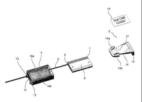
Figure 1 shows the presently preferred first embodiment of the present
invention, in the form of a security seal comprising a seal body 1, a steel
cord
2, an identification element 3 and a transparent polycarbonate cover 4.
For all intents and purposes, seal body 1 and steel cord 2 are
identical to the prior art seals mentioned above. For heavy service, cord 2 is
a galvanised steel cord comprising seven 2.00 mm filaments, its length being
whatever is suitable for the use specified by the user. Body 1 of the seal is
made 85 /oSCR and 15% PSAI plastic.
As can be seen from the drawings, one end 5 of the steel cord 2
is anchored in the interior of body 1 and the other end 6 is free, not shown
in
Figures 1 and 2, but visible in Figures 3 and 4, after closure of the seal.
Body
1 of the seal, on its side opposite the location where end 5 of cord 2 is
anchored, is formed with an internal passage 7 extending between the two
ends of the body. Internally, body 1 is provided with a metallic closure or
locking mechanism associated with internal passage 7 which permits free
passage of the cord when the free end 6 is inserted into internal passage 7,
but pevents its withdrawal in the opposite direction by means of a wedging
action. The locking mechanism, which is internal, is not illustrated in the
CA 02700940 2015-02-24
5 drawings since it is well known and already used in the prior art Cable
Seal
mentioned above and, furthermore, is not in any way related to the novel
features of the present invention.
As can be seen in Figure 1, a larger face 8 of seal body 1 é
substantially smooth and does not carry any marking. The opposite face,
visible in Figure 4, however, carries a laser engraving applied during
manufacture, which includes a number and a bar code which serve to
individualise the seal which is thus unique.
The security seal described up to this point and which comprises
body 1 with its laser engraving and cord 2 is part of the state of the art.
According to the present invention and as mentioned above,
there are two more components, that is to say, the transparent polycarbonate
cover 4 and the identification element 3. Cover 4 is shaped to receive seal
body 1 between the inner surface of an outer wall 9 and an internal dividing
wall 10. On end of cover 4 is open to receive seal body 1 and its other end 11
is closed, with the exception of two small openings 12 and 13 for the
passage of cord 2.
Dividing wall 10 separates the inside of cover 4 into a housing
for receiving the seal body 1 and a smaller housing for receiving a blade
portion 14 of the identification element 3. Element 3 comprises blade 14 and
an end flange 15 which is normal to the blade. At its inner end blade 14 has
an anchor configuration provided with two flexible side arms 14a and 14b
which interact with respective internal shoulders within seal body 1, above
dividing wall 10. The shoulders define stop surfaces 16a and 16b (see
Figure 3) so that, when blade 14 is inserted into body 1, above dividing wall
10, flexible arms 14a and 14b are deformed on passing the shoulder so that,
on expanding again, they become caught behind stop surfaces 16a and
16b (see Figure 3). With identification element 3 thus inserted and locked
within cover 4, flange 15 closes the open end of the cover, thus preventing
removal of seal body I.
Blade 14 of identification element 3 is slightly recessed in its
upper surface so as to define an identification region 17.
CA 02700940 2010-03-26
WO 2009/046510 6
PCT/BR2008/000303
Finally, when the user desires to introduce his own personalised
identification of the seal, he can stick or place any type of label 18 or the
like
in the identification region 17 on blade 14..
The procedure for using the seal is as follows, starting from the
situation shown in Figure 1:
1. Steel cord 2 has already been passed through seal body 1,
through the inside of cover 4 and out of opening 12 (Figure 1);
2. Label 18 is placed on the identification region 17 of blade 14
of the identification element 3 (Figure 1);
3. Cord 2 is pulled to accommodate seal body 1 totally within
transparent cover 4 (Figure 2);
4. The blade 14 of the identification element is inserted into
cover 4 until its anchor is caught behind stop surfaces 16a and 16b, flange
closing body 1 within cover 4. At this moment, the seal is complete and
15 ready for use, it being observed that both the individualised user
marking
(label 18 and Figure 3) and the individualized manufacturer marking (Figure
4), although inaccessible, may be visualized through the transparent walls of
cover 4.
5. The seal may now be closed (sealed) by passing cord 2
through openings in the object to be sealed (not shown in the drawings),
opening 13 in cover 4 and internal passage 7 in seal body 1, its free end 6
then being pulled to the desired position, it being locked in that position by
means of the metallic locking mechanism within the seal body (Figures 3 and
4).
The specific materials mentioned above are not limiting since
any suitable material may be used. In addition, if the user considers
sufficient security to be obtained by using only his own personalisation
(label
18), there would be no need to have manufacturer applied personalisation as
well, making the seal less expensive. In such a case, it would be sufficient
for
only the region of cover 4 above the identification region 17 and label 18 to
be transparent. On the other hand, in order to ensure a greater degree of
security, it is obviously preferable to have an indelible factory marking
(laser
CA 02700940 2010-03-26
WO 2009/046510 7
PCT/BR2008/000303
engraving, for example) together with the user personalisation of the seal so
as to provide double security.
In particular, Figure 5 shows a slightly modified identification
element 19 and, instead of the label 18 of Figures 1 to 4, an electronic
identification chip 20 containing information that, apart from personalisation
of the seal could also include other information regarding the use of the
seal,
the nature, quality or the like of the object or product being sealed and so
on.
It is to be noted that, in the case of using an electronic chip 20, the cover
4
would not necessarily have to be transparent in the region of the chip
provided that the chip could be identified/read electronically through the
material of the cover.
Identification element 19 is almost identical to element 3 except
that it is formed with a groove 21 for receiving an 0-ring seal 22 adjacent
flange 5. When the seal is used with identification element 19, 0-ring seal 22
ensures that the housing or compartment that receives element 19 is
hermetically sealed. This prevents humidity or liquids from reaching the
interior of the compartment and protects the chip 20, label 18 or the like
from
malfunction or damage. In addition, if the hermetically closed compartment
were to contain a liquid or chemical product used to identify a property, use
or specific condition of the seal, that product (for instance, a liquid that
changes colour) could be contained safely within the seal.
Other modifications within the spirit and basic concept of the
present invention and obvious to a person versed in the art after a
consideration of the present specification should be considered to be within
the scope of the invention, as defined in the following claims.