Note: Descriptions are shown in the official language in which they were submitted.
CA 02700958 2010-04-16
PULSE STIMULATION TOOL AND METHOD OF USE
FIELD OF THE INVENTION
[0001] The present invention relates to a pulse stimulation tool for downhole
application and
their use to enhance production of oil and gas wells.
BACKGROUND OF THE INVENTION
[0002] Within a petroleum producing well, the production string forms the
primary conduit
through which production fluids (liquids, gases, or any fluid produced from a
wellbore) are
produced to the surface. The production string is typically assembled with
production tubing and
completion components in a configuration that suits the wellbore conditions
and the production
method. Oil and gas wells typically vary from a few hundred to several
thousand feet in depth,
and there is often insufficient formation pressure to cause the flow of
production fluids through
the production string to the surface.
[0003] Several prior art systems involving different pumping and extraction
devices have been
developed for the surface transfer of production fluids from a well. Downhole
hydraulic pumps
installed deep within the well are commonly used. A surface hydraulic pump
pressurizes power
oil which drives the downhole pump. When a single production string is used,
the power oil is
pumped down the tubing and a mixture of the formation crude oil and power oil
are produced
through the annulus between the casing and the tubing. If two adjacent
production strings are
used, the power oil is pumped through one of the pipes, and the mixture of
formation crude oil
and power oil are produced in the other, parallel pipe.
CA 02700958 2010-04-16
[0004] Prior art artificial lift systems include for example, the progressive
cavity pump and
plunger lift, both of which may be installed on jointed or continuous rods;
electric submersible
pumps (ESPs); gear pumps which may be installed on tubing and powered by
downhole electric
or hydraulic motors; and venturi lift pumps which are run on coiled tubing but
is not a total
production system.
[0005] It is known that pressure pulses can enhance the flow rate of fluids
and mixtures of fluids
and solids from producing formations, therefore, there is a need in the art
for downhole
apparatuses which can produce pressure pulses in order to enhance production
rates.
SUMMARY OF THE INVENTION
[0006] The present invention is directed to a downhole pulse stimulation tool.
In one aspect, the
invention may comprise a tool for use within a production or injection string
including a tubing
string, a rod string and a downhole pump, the tool comprising:
(a) a resonance chamber defined by a cylindrical outer tubular member
defining
at least one pulse emitting opening, the outer tubular member connecting to
the tubing string;
(b) a pulse generator rotatably disposed within the resonance chamber, the
pulse
generator having a longitudinal channel and defining a least one pulse
generating opening, wherein the at least one pulse generating opening
periodically aligns with the pulse emitting opening as the pulse generator
rotates with the resonance chamber to provide fluid communication from the
longitudinal channel to outside the outer tubular member;
(c) wherein the pulse generator is directly or indirectly rotated by the
rod string.
2
CA 02700958 2010-04-16
[0007] In another aspect, the invention may comprise a downhole pulse
stimulation tool for use
within a production or injection string including a tubing string, a
reciprocating rod string and
downhole pump, the tool comprising:
(a) a resonance chamber defined by a cylindrical outer tubular member
defining
at least one pulse emitting opening, the outer tubular member connecting to
the tubing string;
(b) a pulse generator slidingly disposed within the resonance chamber, the
pulse
generator having a central bore and defining a least one pulse generating
opening, wherein the at least one pulse generating opening periodically aligns
with the pulse emitting opening as the pulse' generator reciprocates with the
resonance chamber to provide fluid communication between the central bore
and the exterior of the outer tubular member;
(c) = wherein the pulse generator is directly or indirectly reciprocated by
the rod
string.
BRIEF DESCRIPTION OF THE DRAWINGS
[0008] The invention will now be described by way of an exemplary embodiment
with reference
to the accompanying simplified, diagrammatic, not-to-scale drawings.
[0009] Figure 1 is a schematic view of a pump system incorporating one
embodiment of the
present invention.
[0010] Figure 2A is a cage line view of one embodiment of the invention.
Figure 2B is a side
view; Figure 2C is a cross-sectional view along line A-A of Figure 2B; Figure
2D is an end view;
and Figure 2E is a detail view of Figure 2D. Figure 2F shows a longitudinal
cross-section of one
embodiment of the invention.
3
CA 02700958 2012-03-23
100011 Figure 3 is a schematic representation of a dual pump system, where a
lower inverted
pump drives a pressure emitting tool at the bottom of the tool string.
[00021 Figure 4A is a cage line view of one embodiment having a cruciform slot
channel
pattern, which may be used below an inverted pump. Figure 4B is a longitudinal
cross-sectional
view of this embodiment.
[0003] Figure 5 is a diagrammatic representation of a pulse generator having
helical channels.
[00041 Figure 6A is a cage line view of one embodiment showing helical
channels in a pulse
generator. Figure 6B is a longitudinal cross-sectional view of Fig. 6A.
[00051 Figure 7 is a schematic view of the embodiment of Figures 5 and 6 in an
injection well.
100061 Figure 8 is a cross-sectional view of one embodiment, adapted for use
with a
reciprocating rod string and pump.
DETAILED DESCRIPTION OF THE INVENTION
[0007] The present invention provides for a downhole pulse stimulation tool.
When describing
the present invention, all terms not defined herein have their common art-
recognized meanings.
To the extent that the following description is of a specific embodiment or a
particular use of the
invention, it is intended to be illustrative only, and not limiting of the
claimed invention. The
following description is intended to cover all alternatives, modifications and
equivalents that are
included in the invention, as defined in the appended claims.
"Horizontal" means a plane that is substantially parallel to the plane of the
horizon. "Vertical"
means a plane that is perpendicular to the horizontal plane. One skilled in
the art will recognize
that wellbores may not be strictly vertical or horizontal, and may be slanted
or curved
4
CA 02700958 2010-04-16
in various configurations. As used herein, the term "longtudinal" means
aligned with the axis of
the wellbore, while "transverse" means a plane which is substantially
perpendicular or at an
angle to the longitudinal axis.
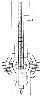
[0019] In one embodiment, the invention comprises a downhole pulse stimulation
tool for use
within a production string including a tubing string (T), a rod string (R) and
a downhole pump
(P). In this embodiment, the tool is placed above the pump. Embodiments of the
tool may be
adapted for use with a progressive cavity pump, a reciprocating pump, an
electric submersible
pump, or other artificial lift solutions.
[0020] The tool (10) comprises a resonance chamber (12) and a pulse generator
(14). The
resonance chamber (12) comprises a housing which forms part of the tubing
string (T) and
defines at least one pulse emitting opening (16). The pulse generator (14) is
disposed within the
tubing string (T) and moves within the resonance chamber (12). The pulse
generator (14)
defines at least one pulse generating opening (18) which periodically aligns
with the pulse
emitting opening (16) as the pulse generator moves within the resonance
chamber (12) housing.
[0021] In one embodiment, shown in Figures 2A-2E, the resonance chamber is
defined by a
hollow cylindrical outer tubular member (12) which defines a pair of pulse
emitting openings
(16), disposed opposite each other. The pulse generator (14) comprises a
generally cylindrical
member which fits within the resonance chamber (12) and rotates within the
resonance chamber.
In one embodiment, the inner profile of the resonance chamber may define a
seat (20) which
may be tapered, which retains the pulse generator. The pulse generator may
also have an outside
taper which may match the inside taper of the pulse generator (14), as shown
in Figure 2C. If
used, the seat (20) prevents downward movement of the pulse generator within
the resonance
chamber. Alternatively, the inner profile of the resonance chamber and the
outer profile of the
5
CA 02700958 2010-04-16
pulse generator may be straight and parallel the longtudinal axis of the outer
tubular member
(12).
[0022] As shown in Figure 2D, the pulse generator (14) defines a plurality of
longitudinal
channels (22), substantially parallel to, and arrayed around, the axis of
rotation. The pulse
generating opening (18) opens into one of the longitudinal channels (22). In
one embodiment,
the pulse generator is installed in a progressive cavity pump system, and is
directly attached to a
rotating rod string, preferably by a threaded attachedment. An actuator (not
shown) attaches
below the pulse generator and attaches to a pump rotor. Thus the rod string
rotatingly drives
both the pulse generator and the pump rotor at the same speed.
[0023] As the pump (P) is rotated, fluid is displaced upward into the tubing
string (T) through
the pulse generator. The pumped fluid passes through the longitudinal
channels, at the same
time the pulse generator rotates within the resonance chamber. The pulse
generating opening
(18) periodically aligns with the pulse emitting opening (16) as the pulse
generator rotates. The
fluid within the pulse generator is at a higher pressure than outside the
tubing string due to the
pump action. As a result, a pulse of fluid pressure is emitted outward from
the resonance
chamber and into the fluid in the annular space surrounding the tubing string.
The frequence of
the pulses depends on the number of pulse generating and emitting openings,
and the speed of
rotation of the pulse generator. The amplitude of the pulses depends on the
pressure differential
between the pressure within the tubing string, and in the formation.
[0024] In one embodiment, there are multiple longitudinal channels, at least
one of which
defines a pulse generating opening. If there are two pulse emitting openings
in the resonance
chamber, two pressure pulses will be emitted every rotation of the pulse
generator. In one
6
CA 02700958 2010-04-16
embodiment, there are five longitudinal channels, with one pulse generating
opening, and two
pulse emitting openings.
[0025] The pulse generator may be directly connected to the rod string by a
threaded connection
to a central connection. Alternatively, an adaptor or other suitable
connection mechanism can be
used in an indirect connection.
[0026] In an alternative embodiment, schematically illustrated in Figure 3,
the pulse stimulation
tool (100) is placed below the pump (P). A slotted sub (110) is attached below
the pump and
provides a fluid intake for the pump as well as the tool (100). A secondary
pump (112) is
inverted below the slotted sub (110) and pumps fluid downward into the tool
(100). The pulse
generator (114) rotates within the resonance chamber (116) housing (117) by
means of rod (102),
which is driven by an extension of the main pump (P). In one embodiment, the
pulse generator
(114) defines channels which are elongate slots (118) arranged in a cruciform
pattern, as shown
in Figure 4. At least one, and preferably all four of the channels (118)
defines a pulse generating
opening (120), and the resonance chamber housing (117) defines at least one,
and preferably four
pulse emitting openings (122), positioned equidistant around the periphery of
the resonance
chamber. Thus, in one embodiment, a pressure pulse is simultaneously emitted
from all four
openings every 90 rotation of the pulse generator.
[0027] In one embodiment, a secondary outlet is formed by a bottom plate
(124)) which has a
cruciform slot pattern (126) which matches the channel (118) pattern in the
pulse generator and
also defines at least one secondary pulse emitting openings (128) which open
downwards
through the bottom plate. Alternatively, the secondary openings (128) may open
laterally. The
secondary outlet bottom plate (124) may be then mounted stationary and flush
against the bottom
of the pulse generator, oriented such that the cruciform slots (126) align
when the pulse emitting
7
CA 02700958 2010-04-16
and generating openings are aligned. Thus, pressure from the resonance chamber
is pulsed
periodically from the pulse emitting openings (122) and from the secondary
openings (128)
simultaneously. As shown in Figure 3, pressure pulses are thereby fired
sideways and downward
into the formation.
[0028] In another alternative embodiment, the pulse generator is not directly
rotated by the rod
string or pump, but rather is rotated by the movement of fluid through the
pulse generator. The
pulse generator (210) rotates on an axle (212) within the resonance chamber
housing (201).
[0029] In one example, shown schematically in Figures 5 and 6A and 6B,
longitudinal channels
(214) are curved within the pulse generator, such that fluid which passes
through the pulse
generator under pressure, causes rotation of the pulse generator about axle
(212). In one
embodiment, the curved channels (214) are helically disposed about the axis of
rotation. At least
one of the curved channels has a pulse generating opening (216). In one
embodiment, the pulse
generator defines an upper pulse generating opening (216A) and a lower pulse
generating
opening (216B), and preferably both the upper and lower pulse generating
openings open into
the same helical channel (214).
[0030] The pitch of the helical channels may be varied. In one embodiment,
each channel makes
at least one rotation within the pulse generator. If upper and lower pulse
generating openings are
provided, the two openings may then be substantially aligned longitudinally on
the resonance
chamber housing (201).
[0031] The resonance chamber may define at least one pair of upper and lower
pulse emitting
openings (218), and preferably two pairs of pulse emitting openings (218) are
provided, as
shown in Figure 6. As will be appreciated by those skilled in the art, if one
pair of pulse
8
CA 02700958 2010-04-16
generating openings (216) are provided, which periodically align with two
pairs of pulse emitting
openings (218), then each rotation of the pulse generator (210) will generate
two sequential
pulses, each pulse comprising a simultaneous pulse from each of the upper and
lower openings
(218).
[0032] In one embodiment, the helical pulse generator (210) may be deployed
below a
progressive cavity pump or an electric submersible pump, but above the pump
intake. The pulse
generator will be rotated by the fluid being sucked into the pump. The
amplitude of the pulses
emitted may be smaller due to the reduced fluid pressure caused by the pump
suction.
[0033] In one embodiment, the helical pulse generator (210) may be deployed
within a injection
well, as shown schematically in Figure 7. The injection fluid (IF) will create
the rotational
motion of the pulse generator as it passes through the device, and will
generate periodic fluid
pressure pulses as described above. A small portion of the injection fluid
will thus escape
through the pulse emitting openings (218) out into the annular space in the
injection well.
[0034] Embodiments of the present invention may also be adapted for use with a
reciprocating
rod string and downhole pump. Reciprocating downhole pumps are conventional
and well-
known in the industry.
[0035] In one embodiment, the tool (300) may comprise a resonance chamber
(312) defined by a
cylindrical outer tubular member (301) defining at least one pulse emitting
opening (302), the
outer tubular member (301) connecting to the tubing string as described above.
Preferably, there
are four pulse emitting openings, each on the same transverse plane, and
positioned equidistant
about the periphery of the resonance chamber (312).
9
CA 02700958 2010-04-16
[0036] The pulse generator (310) is slidingly disposed within the resonance
chamber and is
attached the rod string by means of a rod connector (303), which has a number
of openings
permitting fluid flow upwards into the tubing string. The pulse generator
(310) defines a number
of pulse generating openings (314). In one embodiment, the number of pulse
generating
openings (314) matches the number of pulse emitting openings (302), and are
longitudinally
aligned with the pulse emitting opening(s). Therefore, as the pulse generator
(310) reciprocates
with the rod string, the pulse generating openings (314) periodically align in
the same transverse
plane with the pulse emitting openings (302), once on the upstroke and once on
the downstroke.
As will be appreciated by those skilled in the art, the upstroke pressure
pulse will be stronger
than the downstroke pulse, because of the higher pressure differential caused
by the upstroke.
[0037] In one embodiment, the production of fluids may be enhanced by the use
of chemical
additives injected downhole.
[0038] As will be apparent to those skilled in the art, various modifications,
adaptations and
variations of the foregoing specific disclosure can be made without departing
from the scope of
the invention claimed herein.