Note: Descriptions are shown in the official language in which they were submitted.
CA 02701082 2009-06-19
WO 2008/079033 PCT/NZ2007/000394
1
A TOOTH BAR MOUNTING
FIELD OF THE INVENTION
This invention relates to material handling equipment such as excavators,
backhoes, and- clamping and grappling equipment, and the like. More
particularly it relates to a mounting for a tooth bar on a thumb assembly for
use with such equipment.
BACKGROUND
The use of a thumb, with attached tooth bar, on excavator machinery is
well known. Typically the thumb is used in conjunction with the excavator
bucket so as to make the bucket more effective in picking up material. For
example in demolition sites a thumb is a particularly useful means of
grabbing material which would otherwise be difficult to be picked up solely
by a bucket.
The thumb is typically pivotally mounted to the excavator arm and is
controllable, by an hydraulic ram. The thumb has a tooth bar attached to
its distal outer end, this tooth bar -generally being configured to suit the
particular type of bucket with which it is to be used. For example, the tooth
bar may have four or six teeth depending on the number of teeth mounted
to the edge of the bucket.
CA 02701082 2009-06-19
WO 2008/079033 PCT/NZ2007/000394
2
Because of the differing end user requirements it is often the case that the
manufacturer of the thumb will manufacturer thumb assemblies particularly
suited for the end application.
Consequently there is always a lead time between an end user ordering a
thumb and it actually being delivered from the manufacturer.
Accordingly there is a need for a more modular system whereby the
manufacturer can have a standard thumb sub-assembly and attach to this
a suitable pre-manufactured tooth bar depending on the end users
requirements.
Typically the tooth bar may be welded to the thumb,. but With a more
modular system it is more practical .to have bolt on tooth bars. Bolt on
tooth bars are already known, however those that are known generally
suffer from draw backs - the main one being that they tend to work loose
as a consequence of the forces, and sometimes extreme treatment, which
the thumb experiences during normal use.
It is consequently an object of the present invention to provide a mounting
for a tooth bar on a thumb which at least goes some way to overcoming
the problem of loosening of the'tooth bar during operation of the thumb,
CA 02701082 2009-06-19
WO 2008/079033 PCT/NZ2007/000394
3
alternatively it is an object to at least provide the public with a useful
choice.
SUMMARY OF THE INVENTION
Broadly according to one aspect of the invention there is provided a
mounting for a tooth bar to a mounting surface of a thumb sub-assembly,
the mounting including one or more inwardly narrowing slots located
adjacent the mounting surface and into which a part of the mounting
portion of the tooth bar can be wedgingly engaged, there being means for
fixing the tooth bar into engagement with the mounting surface following
the mounting portion being wedgingly engaged.
BRIEF DSCRIPTION OF THE DRAWINGS
In the following more detailed description of a preferred embodiment of the
invention reference will be made to the accompanying drawings in which:-
Figure 1 illustrates an exploded perspective view of the components of a
thumb sub-assembly and associated tooth bar which is
mountable to the sub-assembly by the mounting according to the
present invention,
Figure 2 illustrates a perspective view of the thumb showing the tooth bar
mounted to the thumb subassembly,
CA 02701082 2009-06-19
WO 2008/079033 PCT/NZ2007/000394
4
Figure 3 illustrates a side elevation view of the thumb when mounted to an
excavator arm, and
Figure 4 illustrates a perspective view of the arrangement shown in Figure
3 but with the thumb inter-engaging with the bucket as shown in
dotted detail in Figure 3.
DESCRIPTION OF THE PREFERRED EMBODIMENT
10. In the drawings Figures 1 and 2 show a tooth bar of a"universaP' type.. By
way of further illustration, however, Figures 3 and 4 show a tooth bar
having four teeth configured to inter-engage with the five teeth on the
cutting edge of the excavator bucket. Other configurations of tooth bar
can be mounted to the thumb assembly using the mounting of the present 15
invention.
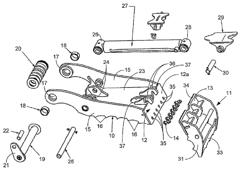
Figure 1 shows the component parts of the thumb. This includes a thumb
subassembly 10 and tooth bar 11. The subassembly 10 has a mounting
plate 12 which forms a mounting surface 12a against which a plate 13 of
20 the tooth bar 11 can engage and be bolted thereto by a series of bolts and
associated nuts 14..
The subassembly 10 includes a pair of side plates 15 which, in
accordance with conventional construction, include along one edge
25 thereof serrations or teeth 15. At the ends of the side plates 15 opposite
to mounting plate 12 are a pair of aligned openings 17. Bushes 18 are
provided for the openings 17. Through the bushes 18 is engaged a pin 19
by which, together with selected spacers 20, the subassembly 10 can be
CA 02701082 2009-06-19
WO 2008/079033 PCT/NZ2007/000394
typically attached to the excavator arm E. To one end of the pin 19 is
attached a radial extending plate 21 to which a retainer bar 22 is fitted.
Between the side plates 15 is a mounting plate 23 which, as more clearly
5 shown in Figures 1 and 4, carries flanges 24 having openings therein
which align with openings in the side plates 15 and through which a thumb
pin 25 can be engaged. This provides a mounting for the bush 26 of the
piston rod of hydraulic ram 27. The body of the hydraulic ram 27 has a
bush 28 which is engaged in bracket 29 via pin 30.
Attached to the mounting plate 13 of the tooth bar 11 is the teeth assembly
31. This can include a plurality of teeth 32 (see Figure 4) or in the more
universal fitting of Figures 1 and 2 a toothed or serrated plate 33.
The upper edge of the mounting plate 13 is preferably bevelled as
indicated,by numeral 34. The mounting plate 13 further includes a series
of openings which align with elongate openings 35 in the mounting plate
12 of the subassembly 10. The bolts 14 pass through thes.e aligned
openings and with the associated nuts bolt the mounting plates 12 and 13
together.
The mounting according to the present invention includes a plurality of
flanges 36 which, in the illustrated form, are a pair of parallel spaced apart
flanges mounted to the mounting plate 23. These flanges 36 are, in the
illustrated form of the construction; located either side of an opening 37
formed in the mounting plate 23.
Each of the mounting flanges 36 have a finger portion 37 which extends
over the mounting surface of the mounting plate 12. These fingers 37
include an edge surface 38 which faces towards the mounting surFace 12a
and is configured such that the distance between the edge 38 and the
CA 02701082 2009-06-19
WO 2008/079033 PCT/NZ2007/000394
6
mounting surface 12a decreases inwardly from the distal ends of finger 37.
The result is a narroWing slot into which the bevelled edge 34 can be
engaged when the mounting plate 13 is bought into engagement with
mounting plate 12. There is thus a wedging action between the edge
38/mounting surface 12a and the mounting plate 13 of the tooth bar 11.
Accordingly when the tooth bar 11 is mounted to the subassembly 10 the
edge 34 is introduced between the edge surFaces 38 of the fingers 37 and
the mounting surface 12a. The tooth bar 11 is then driven into hard
engagement with the fingers 37 so that the edge 34 is firmly wedged into
position. This is shown in more detail in the enlarged part view in Figure 3.
The bolts 14 are then introduced through the aligned openings 35 and the
openings in the mounting plate 13 and the tooth bar thereby bolted onto
the subassembly 10. The elongate nature of the openings 35 ensure that
the mounting plates 12 and 13 can be bolted together irrespective of the
final pbsition of the edge 34 between the fingers 37 and mounting plate
12.
If, during use, the tooth bar 11 loosens it is simply a matter of loosening
off
the nuts/bolts 14 followed by a driving force applied to the tooth bar 11 so
as to force the edge 34 further into wedging engagement between the
mounting surface 12a and the edge surfaces-38 and retightening the nuts
on the bolts.
The present invention thus provides a mounting arrangement for a tooth
bar such that the tooth bar 11 can be readily fitted onto the subassembly
10 and held firmly in place. The invention therefore lessens the likelihood
of the tooth bar 11 working loose. Even though the forces to which the
tooth bar will be subjected during normal use may still cause the tooth bar
to loosen, the likelihood - is less than with conventional mounting
CA 02701082 2009-06-19
WO 2008/079033 PCT/NZ2007/000394
7
arrangements. If loosening does occur it is a matter of retightening in a
simple and straightforward manner.
It will be appreciated by those skilled in the art that the present disclosure
applies to an hydraulically controllable thumb. The invention is also
applicable to a fixed/rigid thumb (i.e. one which is not hydraulically
operable) where the clamping action with the fixed/rigid thumb is achieved
by the crowd action of the bucket.