Note: Descriptions are shown in the official language in which they were submitted.
CA 02701440 2010-03-31
WO 2008/156378 PCT/NZ2008/000151
PEDESTRIAN WARNING SYSTEM
Technical Field
The present invention relates to a pedestrian warning system.
In particular, the present invention relates to an automatic pedestrian
warning
system for warning pedestrians or other road users when a driver of a vehicle
in
which the warning system is installed reacts to a possible road hazard.
Background Art
Pedestrians and other road users at risk of being hit by vehicles typically
stop, look
and listen before moving onto a road. However, many pedestrians become
complacent or may be inattentive and may move onto the road without being
fully
aware of hazards.
A driver may warn pedestrians on the road by sounding the vehicle's horn or
flashing the lights. However, in many circumstances the driver may not have
time
to sound the horn or lights and may instead brake or attempt to avoid the
pedestrian. Even if the driver initiates braking and/or evasive steering there
may be
insufficient time to avoid colliding with the pedestrian. It will be
appreciated that
such dangers are faced not only by pedestrians but also other drivers and
other
road users.
It has thus become desirable to create a system to warn the pedestrian or
other
road user before a potential collision.
One attempt at solving this problem is described in United States Patent No.
6,081,188 by Kutlucinar et al. which forms the basis of the prior art and the
entire
contents of which is herein incorporated by reference.
1
CA 02701440 2010-03-31
WO 2008/156378 PCT/NZ2008/000151
Kutlucinar describes a number of prior art warning systems such as
conventional
brake and hazard lights or operator activated warning lights, horns or sirens.
Kutlucinar describes how these systems may not always be activated in an
emergency as they require user activation in some way, i.e. switching on the
lights
or horn. Kutlucinar eliminates the user-activation requirement by providing
awarning system that automatically activates a visual or audible alarm when a'
detecting circuit detects activation of a"vehicie safety device" such as an
Antilock'
Braking System (ABS), airbag, impact or proximity sensor, parking aid or the
like.
The automatic warning system described by Kutlucinar thus automatically
activates
in an emergency to warn other road users of an emergency situation.
The Kutlucinar system however relies on the activation of a vehicle safety
device
and is thus only activated when the vehicle is in an emergency situation,
which
may often be too late to warn other road users.
While the activation of the warning system on detecting ABS activation may pre-
empt an emergency situation and provide more warning than airbag detecting
systems, not all vehicles have ABS fitted. Moreover, ABS may not activate
until
the brakes begin to `lock-up' which may not occur, or occur too late to
provide
effective warning time.
It would thus be advantageous to provide an improved pedestrian warning system
that may be capable of automatically activating before a collision takes
place. It
would also be advantageous to provide a pedestrian warning system that may be
retrofitted to existing vehicles.
A further hazard faced by road users is the risk of crashing out of sight of
other
road users and thus potentially not receiving help.
All references, including any patents or patent appiications cited in this
specification are hereby incorporated by reference. No admission is made that
any
2
CA 02701440 2010-03-31
WO 2008/156378 PCT/NZ2008/000151
reference constitutes prior art. The discussion of the references states what
their
authors assert, and the applicants reserve the right to challenge the accuracy
and
pertinency of the cited documents. It will be clearly understood that,
although a
number of prior art publications are referred to herein; this reference does
not
constitute an admission that any of these documents form part of the common
general knowledge in the art, in New Zealand or in any other country.
It is acknowledged that the term 'comprise' may, under varying jurisdictions,
be
attributed with either an exclusive or an inciusive meaning. For the purpose
of this
specification, and unless otherwise noted, the term 'comprise' shall have an
inclusive meaning - i.e. that it will be taken to mean an inclusion of not
only the
listed components it directly references, but also other non-specified
components
or elements. This rationale will also be used when the term 'comprised' or
'comprising' is used in relation to one or more steps in a method or process.
It is an object of the present invention to address the foregoing problems or
at least
to provide the public with a useful choice.
Further aspects and advantages of the present invention will become apparent
from the ensuing description which is given by way of example only.
Disclosure of Invention
According to a first aspect of the present invention there is provided a
pedestrian
warning system, said warning system including:
- at least one warning indicator for emitting a warning signal detectable
externally of said vehicle, said warning signal having at least one
audible component;
3
CA 02701440 2010-03-31
WO 2008/156378 PCT/NZ2008/000151
- at least one sensor capable of detecting a speed, velocity and/or
acceleration of said vehicle, the, or each sensor capable of providing a
signal indicative of said speed, velocity and/or acceleration, and
said warning system characterised in the further inclusion of:
- a controller for receiving said sensor signal(s), the, or each, controller'
configured to determine the acceleration of said vehicle from a said `
sensor signal and activate said warning indicator upon determining
acceleration exceeding/deceeding a predetermined threshoid limit.
Preferably said predetermined threshold limit is a level of negative
acceleration (i.e.
deceleration) indicative of a hazard situation, said controller configured to
activate
the warning indicator if said sensor signal indicates the negative
acceleration
deceeding said threshold level. For example, sudden braking, impacts and/or a
rapid change in acceleration may all indicate that the driver has either
noticed a
hazard and is attempting to stop, or the vehicle has collided with an object.
As used herein, the term "deceeding" refers to a parameter decreasing below a
predetermined limit. For example, deceeding may be used herein to describe
when
a negative acceleration (i.e. deceleration) passes (deceeds) a predetermined
level
indicating rapid deceleration.
It will be appreciated that a vehicle's acceleration is not only dependant on
the
forward/backward moving speed but also changes in the direction, and therefore
velocity of the vehicle. Thus, according to one preferred embodiment, said
predetermined threshold limit is a level of acceleration defined with respect
to the
rate of change of direction of the vehicle, e.g. if a driver attempts to avoid
a
pedestrian by turning sharply. This rate of change of direction may be
determined
by input from inertia, gyro, steering wheel sensors, GPS or any other sensor
capable of detecting a change of direction of the vehicle.
4
CA 02701440 2010-03-31
WO 2008/156378 PCT/NZ2008/000151
It will be appreciated that the present invention has particular application
to land
vehicies such as cars, motorbikes, trains, trucks, buses and other automobiles
though this should not be seen to be limiting as the present invention may
also
have application to water vessels, snowmobiles, amusement rides, toys or any
other vehicle.
The, or each, warning indicator is preferably a visual and/or audible
indicator. For
example, the indicator may include one or more of: a flashing or constant
light, '
siren, horn, bell or the like. It will be appreciated that most vehicles are
manufactured with suitable warning indicators fitted in the form of a horn,
security
alarm and/or lights.
However, in preferred embodiments at least one said warning indicator is a
speaker configured to emit a sound simulating the sound emitted by tyres
skidding
on a road surface, i.e. a`screech'. This `screeching' provokes a greater sense
of
danger in a pedestrian or other road users relative to typical vehicle horns.
Preferably, the warning indicator includes a security alarm siren. In many
countries
it is illegal to sound a car horn in residential areas between certain time
periods,
e.g. early morning, and thus a car alarm provides a convenient alternative.
In a further embodiment, the, or each warning indicator is configured to
provide a
signal with one or more variable parameters, dependant on said acceleration
level.
For example, the lights may flash with increased intensity or the speaker/horn
may
sound with a greater volume or varying audibie pattern under high
deceleration.
Preferably at least one said sensor is provided in the form of an interface
connecting the vehicle's speedometer to the controller, the controller
configured to
obtain a signal from the speedometer indicative of the vehicle's speed and
being
capable of calculating the vehicle acceleration from changes in said speed.
5
CA 02701440 2010-03-31
WO 2008/156378 PCT/NZ2008/000151
It will be appreciated that the interface may be relatively easily configured
for
electronic speedometers by connecting a speedometer output from the Engine*
Control Unit (ECU) to the controller, the controller thus receiving the same
speed
signal passed to the speedometer.
However, to connect the controller of the present invention to typical
mechanical
rotation-based speedometers may require additional components and complexity.
For example, in rotating sleeved cable and cup speedometer systems, one end of
'
a cable may be connected to the speedometer shaft and at an opposing end to an
electronic transducer configured to provide an output signal to the controller
proportional to the degree of rotation of the speedometer shaft.
It will be appreciated by one skilled in the art that numerous other
configurations,
including mechanical, electrical, magnetic, and/or optical systems may act as
the
interface and be appropriately connected to a speedometer and configured to
provide an output indicative of the vehicle speed and are considered within
the
scope of the present invention.
It will also be appreciated that numerous other speed, velocity or
acceleration
sensors or systems may be suitable for the present invention and may include:
inertia-based transducers, GPS tracking systems, Doppler effect radar, Pitot
tubes,
or any other means for measuring speed, velocity and/or acceleration.
Preferably the, or each controller includes a microcontroller, microprocessor
or
computer system capable of:
- receiving and processing the signal from a said sensor to determine
said vehicle acceleration, and
- activating a said warning indicator if said signal indicates acceleration
exceeding/deceeding a predetermined threshold limit.
6
CA 02701440 2010-03-31
WO 2008/156378 PCT/NZ2008/000151
In an alternative embodiment said controller is a threshold switch or the like
configured to activate said warning indicator upon receiving a said signal
indicative'
of acceleration at, or exceeding/deceeding said predetermined threshold limit.
For
example, the sensor may be configured to provide a varying voltage signal
proportional to vehicle acceleration, the threshoid switch configured to
activate the '
warning indicator if a predetermined voltage limit is exceeded/deceeded.
Similarly,
electrical current, frequency or other signal parameter may be utilised.
In an alternative embodiment the sensor may be capable of producing a digital
signal to be processed by the controller.
It will be appreciated that in one embodiment the controller and sensor may be
formed as a single device or as distinct capability of a single device.
Preferably the predetermined threshold limit is variable according to a user's
requirements.
Preferably the controller is calibrated such that the predetermined threshold
limit is
outside levels of acceleration experienced in normal driving conditions.
Preferably the warning system includes a manual `on/off' switch to allow a
user to
turn the warning system on or off. In an alternative embodiment one or more
`on/off' switches may be provided for turning the, or each, sensor, warning
indicator
and/or controller on or off.
In some hazard situations a vehicle may come to a rapid halt after crashing
off a
road out of sight of other road users. Thus, the vehicle occupants may be
injured,
trapped or at risk of being injured and without being visible to other road
users may
not receive help.
7
CA 02701440 2010-03-31
WO 2008/156378 PCT/NZ2008/000151
Thus, in one preferred embodiment the warning system may be configured to
continue emitting a warning signal from the, or each, warning indicator after
the'
predetermined acceleration threshold limit has been passed until:
- the warning system and/or indicator is manually switched off;
- a predetermined period of time passes.
In applications where the predetermined acceleration threshold limit is a
level of
negative acceleration, the warning system may be configured to continue
emitting
a warning signal from the, or each warning indicator after the predetermined
acceleration threshold limit has been passed until the controller detects a
positive
acceleration.
Preferably, for vehicles including GPS navigation systems or the like, the
warning
system is configured to trigger a vehicle position logging and/or transmission
when
the warning system detects the predetermined acceleration threshold limit has
been passed. Such a GPS logging system in the vehicle provides a means for
accident investigators to garner more information about the vehicle's
movements
and speed preceding the accident.
Ina further embodiment, the GPS navigation system may be configured to
wirelessly transmit a position and/or speed information when the warning
system
detects the predetermined acceleration threshold limit has been passed. The
transmission may be sent to a central vehicle monitoring station which can
thus
monitor for vehicle accidents or acceleration events and notify emergency
services
if an accident occurs. Transmission of vehicle position information also
allows
emergency services to quickly locate the vehicle.
8
CA 02701440 2010-03-31
WO 2008/156378 PCT/NZ2008/000151
It will be appreciated that the, or each, warning indicator, sensor and/or
controller
may be powered by a vehicle power source such as a vehicle battery or,
alternatively by one or more auxiliary power sources.
In one embodiment the warning system may be configured to receive a signal
from
an ABS sensor indicating ABS activation to activate said warning indicator,
thus
providing a backup to the predetermined acceleration threshold activation. In
icy,
wet or other slippery conditions the vehicle may not exceed/deceed the
predetermined acceleration threshold limit and thus not directly activate the
warning indicator. However, as the ABS is likely to be activated on the user
applying the vehicle brakes in such conditions, an ABS activated warning
indicator
will still activate.
According to another aspect, the controller may be operatively connected to a
vehicle safety device to automatically activate said vehicle safety device
upon
receiving said sensor signal indicating acceleration exceeding/deceeding said
predetermined threshold limit. The vehicle safety device may be any safety
device,
e.g. airbags, ABS, ejector seats and fire extinguishers.
According to another aspect of the present invention there is provided a
method of
retrofitting a pedestrian warning system as aforementioned to a vehicle, said
method including one or more of the following steps:
- attaching at least one warning indicator to the vehicle;
- attaching at least one acceleration sensor to the vehicle; and/or
- attaching at least one controller to the vehicie, said controller
configured to activate a said warning indicator upon receiving a said
sensor signal indicating acceleration exceeding/deceeding a
predetermined threshold limit.
9
CA 02701440 2010-03-31
WO 2008/156378 PCT/NZ2008/000151
It will be appreciated that not all of the aforementioned retrofitting steps m-
ay be
required depending on whether the vehicle:
- has existing warning indicators such as lights and/or horn;
- has existing acceleration sensors;
- has an existing controller or analogous system.
The present invention may thus provide significant advantages over the prior
art
including provision of a warning system capable of at least one or more of:
- being retrofitted to existing vehicles, regardless of the type of vehicle or
whether the vehicle has airbags, ABS, or the like, and/or
- automatically providing a warning signal on detection of acceleration
exceeding/deceeding predetermined limits indicating a hazard situation
and/or change of vehicle direction, thereby potentially activating said
warning indicator more rapidly than prior art systems relying solely on
activation of a vehicle safety device such as ABS, airbags or the like.
Brief Description of Drawings
Further aspects and advantages of the present invention will become apparent
from the following description which is given by way of example only and with
reference to the accompanying drawings in which:
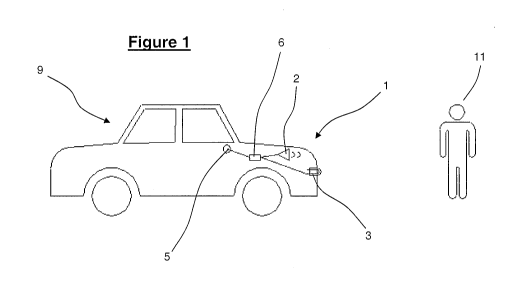
Figure 1 shows a pictorial diagram of a pedestrian warning system according
to one preferred embodiment of the present invention;
Figure 2 shows a schematic system diagram of the functional components of
one preferred embodiment of the present invention;
CA 02701440 2010-03-31
WO 2008/156378 PCT/NZ2008/000151
Figure 3 shows schematic system diagram of the functional components of
another embodiment of the present invention
Best Modes for Carrying out the Invention
Figures 1 and 2 respectively show pictorial and schematic diagrams of one'
preferred embodiment of the present invention in the form of a pedestrian
warning =
system generally indicated by arrow 1 installed in a vehicie (9). The warning
:
system (1) has two warning indicators in the form of a security alarm siren
(2) and
lights (3) for respectively emitting audible and visual signals detectable
externally of
the vehicle. The siren (2) emits a loud sound to warn pedestrians (11) and
other
road users the vehicle (9) is in a hazard situation, e.g. rapidly
decelerating.
The warning system (1) also has a sensor in the form of an interface (4)
coupled to
the vehicle's speedometer (5) to provide an output signal proportional to the
vehicle speed. The interface (4) is connected to a controller in the form of
microcontroller (6) which calculates the acceleration of the vehicle from
changes in
speed. If the microcontroller (6) calculates a level of acceleration that
exceeds/deceeds a predetermined threshold limit, the microcontroller (6) will
send
a signal to activate the security alarm siren (2) and/or lights (3). The
predetermined
threshold limit is a level of negative acceleration (i.e. deceleration)
indicative of a
hazard situation experienced by a driver of the vehicle. For example, sudden
braking, impactsand/or a rapid change in positive acceleration may ail
indicate that
the driver has either noticed or encountered a hazard and is attempting to
stop.
Alternatively rapid negative acceleration may indicate the vehicle has
collided with
an object.
The microcontroller (6) is calibrated when installed to ensure that a
threshold
acceleration limit is set, such that normal driving conditions and
acceleration will
11
CA 02701440 2010-03-31
WO 2008/156378 PCT/NZ2008/000151
not trigger activation of the siren (2) and lights (3) unless the vehicle is
in a hazard
situation.
All components of the warning system (1) are connected to a power supply in
the
form of vehicle battery (7)
Figure 3 shows an alternative embodiment with the sensor provided in the form
of'
an inertia based transducer (8) capable of measuring both forward/backward and
:
lateral acceleration of the vehicle. Thus, when the driver takes evasive
action by
braking and/or swerving to avoid collision, the transducer (8) will provide a
signal to
the microcontroller (6) indicative of the level of acceleration. If this level
of
acceleration exceeds (in the case of lateral positive acceleration) or deceeds
(in
the case of forward/backward negative acceleration) a predetermined threshold
limit, the controller sends a signal to activate the siren (2) and lights (3).
A backup activation system is provided and composed of an ABS sensor (10)
linked to the microcontroller (6) to provide a signal when the ABS sensor (10)
is
activated. This ABS backup system is useful in ensuring warning indicators (2
and
3) are activated even in icy, wet or other slippery conditions where the
vehicle may
not necessarily exceed/deceed the predetermined threshold limit.
Also shown in figure 2 is a vehicle safety device in the form of airbag (13)
that is
automatically activated when the microcontroller (6) calculates a
predetermined
acceleration threshold is exceeded/deceeded. This airbag threshold is set at a
much higher level (i.e. requiring more rapid negative acceleration) than the
warning
indicator threshold, as an airbag (13) will only need to be deployed in
violent
deceleration such as in collisions or the like.
Aspects of the present invention have been described by way of example only
and
it should be appreciated that modifications and additions may be made thereto
without departing from the scope of the appended claims.
12