Note: Descriptions are shown in the official language in which they were submitted.
CA 02701559 2010-04-26
NSC-R850
- 1 -
DESCRIPTION
HIGH STRENGTH PART AND METHOD OF PRODUCTION OF THE SAME
TECHNICAL FIELD
The present invention relates to a member in which
strength is required such as used for a structural member
and reinforcing member of an automobile, more
particularly relates to a part superior in strength after
high temperature shaping and a method of production of
the same.
BACKGROUND ART
To lighten the weight of automobiles, a need
originating in global environmental problems, it is
necessary to make the steel used in automobiles as high
in strength as possible, but in general if making steel
sheet high in strength, the elongation or r value falls
and the shapeability deteriorates. To solve this problem,
technology for hot shaping steel and utilizing the heat
at that time to raise the strength is disclosed in
Japanese Patent Publication (A) No. 2000-234153. This
technology aims to suitably control the steel
composition, heat the steel in the ferrite temperature
region, and utilize the precipitation hardening in that
temperature region so as to raise the strength.
Further, Japanese Patent Publication (A) No. 2000-
87183 proposes high strength steel sheet greatly reduced
in yield strength at the shaping temperature to much
lower than the yield strength at ordinary temperature for
the purpose of improving the precision of press-forming.
However, in these technologies, there may be limits to
the strength obtained. On the other hand, technology for
heating to the high temperature single-phase austenite
region after shaping and in the subsequent cooling
process transforming the steel to a hard phase for the
purpose of obtaining high strength is proposed in
Japanese Patent Publication (A) No. 2000-38640.
CA 02701559 2010-04-26
2 -
However, if heating and rapidly cooling after
shaping, problems may arise in the shape precision. As
technology for overcoming this defect, technology for
heating steel sheet to the single-phase austenite region
and in the subsequent press-forming process cooling the
steel is disclosed in SAE, 2001-01-0078 and Japanese
Patent Publication (A) No. 2001-181833.
In this way, in high strength steel sheet used for
automobiles etc., the higher the strength made, the
greater the above-mentioned problem of shapeability. In
particular, in a high strength member of over 1000 MPa,
as known in the past, there is the basic problem of
hydrogen embrittlement (also called season cracking or
delayed fracture). When used as hot press steel sheet,
while there is little residual stress due to the high
temperature pressing, hydrogen enters the steel at the
time of heating before pressing. Further, the residual
stress of the subsequent working causes greater
susceptibility to hydrogen embrittlement. Therefore, with
just pressing at a high temperature, the inherent problem
is not solved. It is necessary to optimize the process
conditions in the heating process and the integrated
processes to the post-processing.
To reduce the residual stress at the shearing and
the other post-processing, it is sufficient that the
strength at the parts to be post-processed fall.
Technology lowering the cooling rate at portions to be
post-processed so as to make the hardening insufficient
and thereby lowering the strength at those portions is
disclosed in Japanese Patent Publication (A) No. 2003-
328031. According to this method, it is considered that
the strength of part of the part falls and enables easy
shearing or other post-processing. However, when using
this method, the mold structure becomes complicated -
which is disadvantangeous economically. Further, in this
method, hydrogen embrittlement is not alluded to at all.
By this method, even if the steel sheet strength falls
CA 02701559 2010-04-26
- 3 -
somewhat and the residual stress after the post-
processing falls to a certain extent, if hydrogen remains
in the steel, hydrogen embrittlement may undeniably
occur.
DISCLOSURE OF THE INVENTION
The present invention was made to solve this problem
and provides a high strength part superior in resistance
to hydrogen embrittlement able to give a strength of 1200
MPa or more after high temperature shaping and method of
production of the same.
The inventors conducted various studies to solve
this problem. As a result, they discovered that to
suppress hydrogen embrittlement, it is effective to
control the atmosphere in the heating furnace before
shaping so as to reduce the amount of hydrogen in the
steel and then reduce or eliminate the residual stress by
the post-processing method. That is, the present
invention has the following as its gists:
(1) A method of production of a high strength part
characterized by using steel sheet containing, by wt%, C:
0.05 to 0.55% and Mn: 0.1 to 3% in chemical composition,
heating the steel sheet in an atmosphere of, by volume
percent, hydrogen in an amount of 10% or less (including
0%) and of a dew point of 30 C or less until the Ac3 to
the melting point, then starting the shaping at a
temperature higher than the temperature at which ferrite,
pearlite, bainite, and martensite transformation occurs,
cooling and hardening after shaping in the mold to
produce a high strength part, then further performing
post-processing.
(2) A method of production of a high strength part
characterized by using steel sheet containing, by wt%, C:
0.05 to 0.55% and Mn: 0.1 to 3% and having a balance of
Fe and unavoidable impurities in chemical composition,
heating the steel sheet in an atmosphere of, by volume
percent, hydrogen in an amount of 10% or less (including
0%) and of a dew point of 30 C or less to the Ac3 to the
CA 02701559 2010-04-26
- 4 -
melting point, then starting the shaping at a temperature
higher than the temperature where ferrite, pearlite,
bainite, and martensite transformation occurs, cooling
and hardening after shaping in the mold to produce a high
strength part, shearing it, then shearing again 1 to 2000
m from the worked end.
(3) A method of production of a high strength part
characterized by using steel sheet containing, by wt%, C:
0.05 to 0.55% and Mn: 0.1 to 3% and having a balance of
Fe and unavoidable impurities in chemical composition,
heating the steel sheet in an atmosphere with an amount
of hydrogen, by volume percent, of 10% or less (including
0%) and of a dew point of 30 C or less to the Ac3 to the
melting point, then starting the shaping at a temperature
higher than the temperature where ferrite, pearlite,
bainite, and martensite transformation occurs, cooling
and hardening after shaping in the mold to produce a high
strength part, then shearing and pressing the sheared end
face.
(4) A method of production of a high strength part
as set forth in (3), characterized by using coining as
the method of press working.
(5) A method of production of a high strength part
characterized by using steel sheet containing, by wt%, C:
0.05 to 0.55% and Mn: 0.1 to 3% and having a balance of
Fe and unavoidable impurities in chemical composition,
heating the steel sheet in an atmosphere of, by volume
percent, hydrogen in an amount of 10% or less (including
0%) and of a dew point of 30 C or less to the Ac3 to the
melting point, then starting the shaping at a temperature
higher than the temperature where ferrite, pearlite,
bainite, and martensite transformation occurs, and
cooling and hardening after shaping in the mold to
produce a high strength part and punching or cutting this
during which using a cutting blade having a step
difference continuously decreasing from the radius of
CA 02701559 2010-04-26
- 5 -
curvature or width of the blade base by 0.01 to 3.0 mm in
the direction from the blade base to the blade tip and
having a height of 1/2 the thickness of the steel sheet
to 100 mm for the punching or cutting.
(6) A method of production of a high strength part
as set forth in (5), characterized by having a step
difference continuously decreasing from the radius of
curvature or width of the blade bas=e by 0.01 to 3.0 mm in
the direction from the blade base to the blade tip and by
D/H being 0.5 or less when a height of said step
difference of H (mm) and a difference of the radius of
curvature or width of the blade base and blade tip is D
(mm).
(7) A method of production of a high strength part
characterized by using steel sheet containing, by wt%, C:
0.05 to 0.55% and Mn: 0.1 to 3% and having a balance of
Fe and unavoidable impurities in chemical composition,
heating the steel sheet in an atmosphere having an amount
of hydrogen by volume percent of 10% or less (including
0%) and of a dew point of 30 C or less to the Ac3 to the
melting point, then starting shaping at a temperature
higher than the temperature where ferrite, pearlite,
bainite, and martensite transformation occurs, cooling
and hardening after shaping in the mold to produce a high
strength part, then punching the steel sheet forming the
worked material using a die and punch to cut it to
shearing and sheared parts to form the worked material to
a predetermined shape during which using a punching tool
having a bending blade having a shape projecting out at
the front of the punch and/or die and having a radius of
curvature of the shoulder of the bending blade of 0.2 mm
or more to make the clearance 25% or less.
(8) A method of production of a high strength part
characterized by using steel sheet containing, by wt%, C:
0.05 to 0.55% and Mn: 0.1 to 3% and having a balance of
Fe and unavoidable impurities in chemical composition,
heating the steel sheet in an atmosphere, by volume
CA 02701559 2010-04-26
- 6 -
percent, of hydrogen in an amount of 10% or less
(including 0%) and of a dew point of 30 C or less to the
Ac3 to the melting point, then starting the shaping at a
temperature higher than the temperature where ferrite,
pearlite, bainite, and martensite transformation occurs,
cooling and hardening after shaping in the mold to
produce a high strength part, then punching the steel
sheet forming the worked material using a die and punch
to cut it to shearing and sheared parts to form the
worked material to a predetermined shape during which
using a punching tool having a shape projecting out at
the front of the punch and/or die and having an angle of
the shoulder of the bending blade of 100 to 170 to make
the clearance 25% or less.
(9) A method of production of a high strength part
characterized by using steel sheet containing, by wt%, C:
0.05 to 0.55% and Mn: 0.1 to 3% and having a balance of
Fe and unavoidable impurities in chemical composition,
heating the steel sheet in an atmosphere, by volume
percent, of hydrogen in an amount of 100 or less
(including 0%) and of a dew point of 30 C or less to the
Ac3 to the melting point, then starting the shaping at a
temperature higher than the temperature where ferrite,
pearlite, bainite, and martensite transformation occurs,
cooling and hardening after shaping in the mold to
produce a high strength part, then punching the steel
sheet forming the worked material using a die and punch
to cut it into a shearing part and a sheared part and
make the worked material a predetermined shape during
which using a punching tool having a bending blade having
a shape projecting out at the front of the punch and/or
die and having a radius of curvature of the shoulder of
the bending blade of 0.2 mm or more and an angle of the
shoulder of the bending blade of 100 to 170 to make the
clearance 25% or less.
(10) A method of production of a high strength part
CA 02701559 2010-04-26
- 7 -
characterized by using steel sheet containing, by wt%, C:
0.05 to 0.55% and Mn: 0.1 to 3% and having a balance of
Fe and unavoidable impurities in chemical composition,
heating the steel sheet in an atmosphere of, by volume
percent, hydrogen in an amount of 10% or less (including
0%) and of a dew point of 30 C or less to the Ac3 to the
melting point, then starting the press-forming at a
temperature higher than the temperature where ferrite,
pearlite, bainite, and martensite transformation occurs,
and cooling and hardening after shaping in the mold to
produce a high strength part during which applying the
shearing near bottom dead point.
(11) A method of production of a high strength part
characterized by using steel sheet containing, by wt%, C:
0.05 to 0.55% and Mn: 0.1 to 3% and having a balance of
Fe and unavoidable impurities in chemical composition,
heating the steel sheet in an atmosphere of, by volume
percent, hydrogen in an amount of 10% or less and having
a dew point of 30 C or less to the Ac3 to the melting
point, starting the shaping at a temperature higher than
the temperature where ferrite, pearlite, bainite, and
martensite transformation occurs, cooling and hardening
after shaping in the mold to produce a high strength
part, then melting part of the part to cut it.
(12) A method of production of a high strength part
as set forth in (11), characterized by using laser
working as the method of working for melting and cutting
part of the part.
(13) A method of production of a high strength part
as set forth in (11), characterized by using plasma
cutting as the method of working for melting and cutting
part of the part.
(14) A method of production of a high strength part
characterized by using steel sheet containing, by wt%, C:
0.05 to 0.55% and Mn: 0.1 to 3% and having a balance of
Fe and unavoidable impurities in chemical composition,
heating the steel sheet in an atmosphere of, by volume
CA 02701559 2010-04-26
- 8 -
percent, hydrogen in an amount of 10% or less and of a
dew point of 30 C or less to the Ac3 to the melting point,
then starting the shaping at a temperature higher than
the temperature where ferrite, pearlite, bainite, and
martensite transformation occurs, cooling and hardening
after shaping in the mold to produce a high strength
part, then machining this to perforate it or cut around
the part.
(15) A method of production of a high strength part
characterized by using steel sheet containing, by wt%, C:
0.05 to 0.55% and Mn: 0.1 to 3% and having a balance of
Fe and unavoidable impurities in chemical composition,
heating the steel sheet in an atmosphere of, by volume
percent, hydrogen in an amount of 10% or less and of a
dew point of 30 C or less to the Ac3 to the melting point,
then starting the shaping at a temperature higher than
the temperature where ferrite, pearlite, bainite, and
martensite transformation occurs, cooling and hardening
after shaping in the mold to produce a high strength
part, then shearing and mechanically differentially
cutting the cut surface of the sheared part to remove a
thickness of 0.05 mm or more.
(16) A method of production of a high strength part
as set forth in any one of (1) to (15) characterized in
that the chemical composition of said steel sheet is, by
wt%, C: 0.05 to 0.55%, Mn: 0.1 to 3%, Al: 0.005 to 0.1%,
S: 0.02% or less, P: 0.03% or less, and N: 0.01% or less
and the balance of Fe and unavoidable impurities.
(17) A method of production of a high strength part
as set forth in any one of (1) to (15) characterized in
that the chemical composition of said steel sheet is, by
wt%, C: 0.05 to 0.55%, Mn: 0.1 to 3%, Si: 1.0% or less,
Al: 0.005 to 0.1%, S: 0.02% or less, P: 0.03% or less,
Cr: 0.01 to 1.0%, and N: 0.01% or less and the balance of
Fe and unavoidable impurities.
(18) A method of production of a high strength part
as set forth in any one of claims 1 to 15 characterized
CA 02701559 2010-04-26
- 9 -
in that the chemical composition of said steel sheet is,
by wto, C: 0.05 to 0.550, Mn: 0.1 to 30, Si: 1.0% or less,
Al: 0.005 to 0.1%, S: 0.02% or less, P: 0.03% or less, Cr:
0.01 to 1.0%, B: 0.0002o to 0.0050%, Ti: (3.42 x N +
0.001)a or less, 3.99 x(C-0.1)0 or less, and N: 0.01% or
less and the balance of Fe and unavoidable impurities.
(19) A method of production of a high strength part
as set forth in any one of claims 1 to 15 characterized in
that the chemical composition of said steel sheet is, by
wta, C: 0.05 to 0.550, Mn: 0.1 to 30, Si: 1.00 or less,
Al: 0.005 to 0.10, S: 0.02% or less, P: 0.03% or less, Cr:
0.01 to 1.0%, B: 0.0002% to 0.0050%, Ti: (3.42 x N +
0.001)0 or less, 3.99 x(C-0.1)0 or less, N: 0.01% or
less, and 0: 0.015% or less and the balance of Fe and
unavoidable impurities.
(20) A method of production of a high strength part
as set forth in any one of (1) to (15) characterized in
that said steel sheet is treated by any of aluminum
plating, aluminum-zinc plating, and zinc plating.
(21) A high strength part characterized by being
produced by a method as set forth in any one of (1) to
(20).
(22) A method of production of a high strength part
characterized by using steel sheet containing, by wt%, C:
0.05 to 0.55% and Mn: 0.1 to 3% in chemical composition and
having a tensile strength of 980 MPa or more, heating the
steel sheet in an atmosphere of, by volume percent,
hydrogen in an amount of 10% or less, including0o and of a
dew point of 30 C or less until the Ac3 to the melting
point, then starting the shaping at a temperature higher
than the temperature at which ferrite, pearlite, bainite,
and martensite transformation occurs, cooling and hardening
after shaping in the mold to produce a high strength part,
CA 02701559 2010-04-26
- 9a -
shearing said high strength part, then again shearing
200 pm to 2000 pm from the worked end.
(23) A method of production of a high strength part
characterized by using steel sheet containing, by wto, C:
0.05 to 0.55% and Mn: 0.1 to 3% and having a balance of Fe
and unavoidable impurities in chemical composition, heating
the steel sheet in an atmosphere of, by volume percent,
hydrogen in an amount of 100 or less, including 0%, and of
a dew point of 30 C or less to the Ac3 to the melting point,
then starting the shaping at a temperature higher than the
temperature where ferrite, pearlite, bainite, and
martensite transformation occurs, cooling and hardening
after shaping in the mold to produce a high strength part,
shearing said high strength part, then shearing again 1 to
2000 pm from the worked end.
(24) A method of production of a high strength part
characterized by using steel sheet containing, by masso, C:
0.05 to 0.55% and Mn: 0.1 to 3o and having a balance of Fe
and unavoidable impurities in chemical composition, heating
the steel sheet in an atmosphere of, by volume percent,
hydrogen in an amount of 100 or less, including 0%, and of
a dew point of 30 C or less to the Ac3 to the melting point,
then starting the shaping at a temperature higher than the
temperature where ferrite, pearlite, bainite, and
martensite transformation occurs, and cooling and hardening
after shaping in the mold to produce a high strength part
and punching or cutting said high strength part, during
which using a punch or die comprised of a blade tip having a
tip parallel part, a step difference, and blade base, in
which punch or die the step difference having a height of
1/2 the thickness of the steel sheet to 100 mm, the step
difference having a width continuously decreasing by 0.01
CA 02701559 2010-04-26
- 9b -
to 3.0 mm from the blade base to the blade tip, a value of
D/H being 0.5 or less when a height of said step difference
of H and a difference of the width of the blade base and
blade tip is D, and an angle formed by the step difference
and a parallel part of the blade base is 95 to 179 degrees,
to punch or cut with a clearance between the parallel part
of the blade base and die of 4.3 to 250.
(25) A method of production of a high strength part
characterized by using steel sheet containing, by wto, C:
0.05 to 0.55o and Mn: 0.1 to 3o and having a balance of Fe
and unavoidable impurities in chemical composition, heating
the steel sheet in an atmosphere having an amount of
hydrogen by volume percent of 10% or less, including 00,
and of a dew point of 30 C or less to the Ac3 to the melting
point, then starting shaping at a temperature higher than
the temperature where ferrite, pearlite, bainite, and
martensite transformation occurs, cooling and hardening
after shaping in the mold to produce a high strength part,
then punching the steel sheet forming the worked material
using a die and punch to cut said worked material to
shearing and sheared parts to form the worked material to a
predetermined shape during which using a punching tool
having a bending blade having a shape projecting out at the
front of the cutting blade of the punch or die, or both the
punch and die, so as to give a tensile stress to the
material without cutting the material, and having a radius
of curvature of the shoulder of the bending blade of 0.2 mm
or more to make the clearance 25% or less.
(26) A method of production of a high strength part
characterized by using steel sheet containing, by wto, C:
0.05 to 0.55% and Mn: 0.1 to 3% and having a balance of Fe
and unavoidable impurities in chemical composition, heating
CA 02701559 2010-04-26
- 9c -
the steel sheet in an atmosphere of, by volume percent,
hydrogen in an amount of 10% or less, including 0%, and of
a dew point of 30 C or less to the Ac3 to the melting point,
then starting the press-forming at a temperature higher
than the temperature where ferrite, pearlite, bainite, and
martensite transformation occurs, and cooling and hardening
after shaping in the mold to produce a high strength part
during which hot shaping, when the steel sheet is
austenite, applying shearing within 10 mm from bottom dead
center of a press forming punch.
(27) A method of production of a high strength part
characterized by using an aluminum plated, aluminum-zinc
plated or zinc plated sheet steel sheet containing, by wt%,
C: 0.05 to 0.55% and Mn: 0.1 to 3% and having a balance of
Fe and unavoidable impurities in chemical composition,
heating the steel sheet in an atmosphere of, by volume
percent, hydrogen in an amount of 2% or less, including
0%, and of a dew point of 30 C or less to the Ac3 to the
melting point, then starting the press-forming at a
temperature higher than the temperature where ferrite,
pearlite, bainite, and martensite transformation occurs,
and cooling and hardening after shaping in the mold to
produce a high strength part during which hot shaping,
when the steel sheet is austenite, applying shearing
within 10 mm from bottom dead center of a press forming
punch.
BRIEF DESCRIPTION OF THE DRAWINGS
FIG. 1 is a view of the concept of generation of
tensile residual stress due to punching.
FIG. 2 is a view of the concept of removal of a
plastic worked layer or other affected parts.
CA 02701559 2010-04-26
- 9d -
FIG. 3 is a view of the cut state by a cutting blade
having a blade tip shape where a step difference forms the
blade tip.
FIG. 4 is a view of the cut state by a cutting blade
having a blade tip shape having a tip parallel part at the
tip of the step difference.
FIG. 5 is a view of a conventional punching method.
FIG. 6 is a view of the cut state by a punch having a
two-step structure.
CA 02701559 2010-04-26
- 10 -
FIG. 7 is a view of the material deformation
behavior in the case where there is a bending blade.
FIG. 8 is a view of the relationship of the radius
of curvature Rp of the bending blade and the residual
stress.
FIG. 9 is a view of the relationship of the angle Op
of the vertical wall of the bending blade A and the
residual stress.
FIG. 10 is a view of the relationship of the height
of the bending blade and the residual stress.
FIG. 11 is a view of the relationship between the
clearance and residual stress.
FIG. 12 is a view of a piercing test piece.
FIG. 13 is a view of a shearing test piece.
FIG. 14 is a view of a tool cross-sectional shape.
FIG. 15 is a view of a shape of a punch.
FIG. 16 is a view of a shape of a die.
FIG. 17 is a view of a shape of a shaped article.
FIG. 18 is a view of the state of a shearing
position.
FIG. 19 is a view of the cross-sectional shape of a
coining tool.
FIG. 20 is a view of the cross-sectional shape of a
mold of Example 4.
FIG. 21 is a view of the cross-sectional shape of a
tool of Example 5.
FIG. 22 is a view of a shaping punch of Example 5.
FIG. 23 is a view of a shaping die of Example 5.
FIG. 24 is a view of a shaped part of Example 5.
FIG. 25 is a view of the state of a post-processing
position of Example 6.
BEST MODE FOR WORKING THE INVENTION
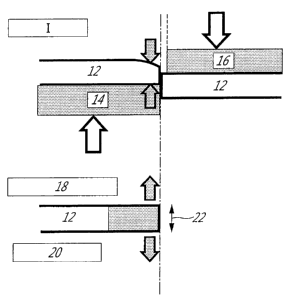
The following is a list of reference numerals used
in the drawings.
CA 02701559 2010-04-26
- 10a -
Reference Label
Numeral
I Ordinary Working
12 Steel Sheet
14 Die
16 Punch
18 Stress Release After Working
20 Work Affected Part
22 Residual Stress
24 Punch Diameter: ~ 10.0 mm
26 Die Diameter:~ 10.5 mm
28 Punch Diameter: ~ 12.0 mm
30 Die Diameter: ~ 12.5 mm
II First Working
III Second Working
32 Cutting Blade
34 Blade Vertical Wall Angle: 0
36 Blade Shoulder Curvature Radius: R
38 Blade Base
40 Parallel Part
42 Sheet Holder
44 Step Difference Height: H
46 Thickness t
48 Worked Material
50 Material Cut Part M
52 Step Difference
54 Bending Blade Height Hp
56 Blade Bottom Surface (Blade Tip)
58 Clearance C
60 Radius Difference or Width Difference:
D
62 Tip Parallel Part Length: HP
64 Punch Die Movement Direction
68 Worked Material Shearing Part
CA 02701559 2010-04-26
- lOb -
70 Worked Material Sheared Part
72 Punch Diameter Ap
74 Bending Blade Shoulder Curvature
Radius Rp
76 Bending Blade Vertical Wall Angle: Op
78 Blade Tip P
80 Cutting Blade B
82 Bending Blade A
84 Bending Blade Rising Part Q
86 Distance Dp between PQ
88 Punch Die Distance C
90 Bending Blade Vertical Wall
92 Bending Blade Floor Surface
94 Bending Blade
96 Tensile Stress
98 Claim
100 Punch Bending Blade Cutting Blade
Distance Dp
102 Punch Bending Blade Shoulder
Curvature Radius Rp
104 Punch Bending Blade Shoulder Angle
Op
106 Punch Bending Blade Height Hp
108 Die Hole Inside Diameter Ad
110 Material
112 Die Bending Blade Height Hd
114 Die Bending Blade Shoulder Angle Od
116 Die Bending Blade Shoulder Curvature
Radius Rd
118 Die Bending Blade / Cutting Blade
Distance Dd
CA 02701559 2010-04-26
- lOc -
The present invention provides a high strength part
superior in resistance to hydrogen embrittlement by
controlling the atmosphere in the heating furnace when
heating steel sheet before shaping to obtain a high
strength part so as to reduce the amount of hydrogen in
CA 02701559 2010-04-26
- 11 -
the steel and by reducing the residual stress by the
post-processing method and a method of production of the
same.
Below, the present invention will be explained in
more detail. First, the reasons for limitation of the
conditions in the present invention will be explained.
The amount of hydrogen at the time of heating was
made, by volume percent, 100 or less because when the
amount of hydrogen is over the limit, the amount of
hydrogen entering the steel sheet during heating becomes
great and the resistance to hydrogen embrittlement falls.
Further, the dew point in the atmosphere was made 30 C or
less because with a dew point greater than this, the
amount of hydrogen entering the steel sheet during
heating becomes greater and the resistance to hydrogen
embrittlement falls.
The heating temperature of the steel sheet is made
the Ac3 to the melting point so as to make the structure
of the steel sheet austenite for hardening and
strengthening after shaping. Further, if the heating
temperature is higher than the melting point, press-
forming becomes impossible.
The heating temperature of the steel sheet is made
the Ac3 to the melting point so as to make the structure
of the steel sheet austenite for hardening and
strengthening after shaping. Further, if the heating
temperature is higher than the melting point, press-
forming becomes impossible.
The shaping starting temperature is made a
temperature higher than the temperature where ferrite,
pearlite, bainite, and martensite transformation occurs
because if shaped at a temperature lower than -this, the
hardness after shaping is insufficient.
By heating steel sheet under the above conditions
and using the press method to shape it, cooling and
hardening after shaping in the mold, then post-processing
it, it is possible to produce a high strength part. The
CA 02701559 2010-04-26
- 12 -
"hardening" is the method of strengthening steel by
cooling by a cooling rate faster than the critical
cooling rate determined by the composition so as to cause
a martensite transformation.
Next, a different method of working by the above
post-processing will be explained.
The method of working of claim 2 will be explained.
The inventors investigated in detail the plastic
worked layer and residual stress affected zone at the
worked end face of the shearing such as the punch
piercing and cutting and as a result learned that there
is a plastic worked layer etc. present over about 2000 m
from the worked end. As shown in FIG. 1, at the time of
shearing, the steel sheet is worked in a compressed
state. After working, the compressed state is released,
so it is believed that residual stress of tension occurs.
Therefore, as shown in FIG. 2, in the plastic worked
layer or other affected zone, the partial rise in
strength due to the plastic working or the resistance to
the compression force due to the tensile residual stress
due to the second working causes the amount of
compression at the time of working to become smaller and
the amount of deformation of the opening after cutting to
become smaller, so the residual stress can be reduced.
Therefore, if working the part of over 2000 m of the
worked end in range again, there is no plastic worked
layer or other affected zone, so the part is worked while
again receiving a large compression force. When this is
released after working, the residual stress is not
reduced and the cracking resistance is not improved, so
the upper limit was made 2000 m. Further, the lower
limit was set to 1 m since working while controlling
this to a range of less than 1 m is difficult. The most
preferable range of working is 200 to 1000 m.
Further, the residual stress at the cross-section of
the worked part is measured by an X-ray residual stress
CA 02701559 2010-04-26
- 13 -
= measurement apparatus according to the method described
in "X-Ray Stress Measurement Method Standard (2002
Edition)- Ferrous Metal Section", Japan Society of
Materials Science, March 2002. The details are as
follows. The parallel tilt method is used to measure 20-
sin2yJ using the reflection X-rays of the 211 plane of a
body centered cubic lattice. The 20 measurement range at
this time is about 150 to 162 . Cr-Ka was used as the X-
ray target, the tube current and tube voltage were made
30 kV/10 mA, and the X-ray incidence slit was made 1 mm
square. The value obtained by multiplying the stress
constant K with the inclination of the 20-sin2yr curve was
made the residual stress. At this time, the stress
constant K was made -32.44 kgf/deg.
Under the above conditions, in the case of a pierced
hole cross-section, yJ(mm)=20, 25, 30, 35, 40, 45 is
measured, while in the case of a cut surface yf(mm)=0, 20,
25, 30, 35, 40, 45 is measured. The measurement was
conducted in a thickness direction of 0 and directions
inclined by 23 and 45 from that for a total of three
measurements. The average value was used as the residual
stress.
The method of shearing such as punching or cutting
is not particularly limited. It is possible to use any
known method. Regarding the working temperature, the
effect of the present invention is obtained from room
temperature to 1000 C in range.
By the above post-processing, the residual stress of
the tension at the worked end face becomes 600 MPa or
less, so in general when assuming steel sheet of 980 MPa
or more, the residual stress becomes less than the yield
stress and cracks no longer occur. Further, when the
residual stress of compression, basically stress does not
act in a direction where cracks form in the steel sheet
at the ends, so cracks no longer occur. For this reason,
CA 02701559 2010-04-26
- 14 -
the residual stress of tension at the end face in
shearing such as punching or cutting preferably is made
600 MPa or less or the residual stress of compression.
Next, the methods of working of claims 3 and 4 will
be explained.
To suppress hydrogen embrittlement, in addition to
press working the parts where there is residual stress
arising due to shearing, it is effective to impart
residual stress of compression. The end faces which were
sheared are press worked because the residual stress of
tension believed to cause hydrogen embrittlement after
shearing is high at sheared ends and if press working
such locations, the residual stress of tension falls and
the resistance to hydrogen embrittlement is improved. As
the method for press working the sheared end faces, any
method may be used, but industrially the method of using
coining as shown in claim 5 is economically superior.
Next, the methods of working shown in claims 5 and 6
will be explained.
The sheared end faces are worked in the state with
the steel sheet compressed when working them as shown in
FIG. 1. After working, the compressed state is released,
so residual stress of tension is believed to arise.
Therefore, the inventors discovered that by widening
holes or pressing the front surfaces of the end faces at
the entire cross-section of the plastic worked layer or
other affected zone, the partial rise in strength due to
plastic working or the resistance to the compression
force due to the residual stress of tension enables
control so that the release displacement after complete
cutting becomes the compression side, i.e., a single-step
working method. That is, if enlarging a hole or pressing
over a part in a range over 2000 m from the worked end,
the hole is widened and the end face is pressed at one
time. Since this is released after working, the residual
stress ends up at the compression side at the end face.
To be able to obtain this by a single working operation
CA 02701559 2010-04-26
- 15 -
using a die and punch, the shape of the blade tip as
shown in FIGS. 3, 4 is important. FIG. 3 has a step
difference forming the blade tip, while FIG. 4 has a tip
parallel part at the tip of the step difference.
When providing a step difference continuously
decreasing from the radius of curvature or width of the
blade base in the direction from the blade base to the
blade tip, if the reduction in the radius of curvature or
width is less than 0.01 mm, the situation ends up
becoming no different from ordinary punching or cutting,
so a large tensile stress ends up remaining at the end
face. On the other hand, if the amount of reduction of
the radius of curvature or width is over 3.0 mm, the de
facto clearance becomes large, so the burring of the
worked end face ends up becoming larger.
Further, if the height of the blade vertical wall
(height of step difference) is less than 1/2 of the
thickness of the worked steel sheet, after punching once,
it is no longer possible to press the worked end face
from the side face of the step difference, so the
situation becomes no different from ordinary punching or
cutting and a large tensile stress ends up remaining at
the worked end face. On the other hand, if the height is
over 100 mm, the stroke becomes larger or shorter
lifetime of the blade itself is a concern.
Further, the angle formed by the parallel part of
the cutting blade and the step difference (blade vertical
wall angle 0) is preferably 95 to 179 , more preferably
at least 140 .
In FIG. 3 and FIG. 4, the step difference is shaped
having a radius of curvature, but a blade linearly
reduced in width from the blade base is also included in
the scope of the invention.
Further, regarding the shape of the cutting blade,
D/H is important when the difference of the radius of
curvature or width of the blade base and blade tip is D
(mm) and the height of the step difference is H (mm). If
CA 02701559 2010-04-26
- 16 -
the value is less than 0.5, the drop in blade life or
burring is suppressed, so the value is preferably made
0.5 or less.
On the other hand, chamfering of the blade tip such
as disclosed in Japanese Patent Publication (A) No. 5-
23755 and Japanese Patent Publication (A) No. 8-57557 is
effective for reducing burring, prolonging blade life,
and preventing cracking of relatively low strength steel
sheet, but in the present invention, it is most important
that the steel sheet be shaped under predetermined
conditions, then the once punched end face or cut end
face be again pushed apart, so it is not particularly
necessary to chamber the blade tip in order to reduce the
residual stress or make it the compression side.
Further, the residual stress at the worked end face
is measured under the above-mentioned conditions by an X-
ray residual stress measurement apparatus according to
the method described in "X-Ray Stress Measurement Method
Standards (2002 edition)- Ferrous Metal Section", Japan
Society of Materials Science, March 2002.
The method of shearing such as punching or cutting
is not particularly limited. Any known method may be
used. For the working temperature, the effect of the
present invention is obtained in the range of room
temperature to 1000 C.
Further, regarding the residual stress, if zero or
the compression side, basically, no reaction acts at the
end in the direction where the steel sheet will crack, so
cracks no longer occur. Further, pressing at not more
than 600 MPa is effective for preventing cracks.
Next, the methods of working of claims 7, 8, and 9
will be explained.
The inventors considered the above problems and
discovered that by making the punch shape a two-step
structure of the bending blade A and cutting blade B
shown in FIG. 6 it is possible to reduce the residual
stress at the punched end face.
CA 02701559 2010-04-26
- 17 -
The reasons are considered to be as follows.
In ordinary punching, the part deformed by the punch
and die shown in FIG. 5 (hardened layer) is subjected to
a large tensile or compressive strain. For this reason,
the work hardening of that part becomes remarkable, so
the ductility of the end face deteriorates. However, when
making the punch shape the two-step structure comprised
of the cutting blade B and bending blade A such as shown
in the present invention (FIG. 6), as shown in FIG. 7,
when the part cut by the cutting blade B (material cut
part M) is given tensile stress by the bending blade A,
the progression of cracks arising due to the cutting
blade B and die shoulder is promoted by the tensile
stress and the material is cut by the cutting blade B
without compression, so the residual stress of tension
after punching becomes lower and the drop in the
allowable amount of hydrogen entering from the
environment can be suppressed.
Further, the inventors conducted detailed studies on
the shape of the bending blade and discovered that unless
making the shape of the bending blade a predetermined
shape, a sufficient effect of reduction of the residual
stress cannot be obtained.
That is, when the shape of the bending blade A is
not the predetermined shape, the material is cut by the
bending blade A, so the part M cut by the cutting blade B
cannot be given sufficient tensile stress by the bending.
However, by making the shape of the bending blade a shape
where the material is not cut by the bending blade
itself, the residual stress can be reduced.
FIG. 8 shows the relationship between the radius of
curvature Rp and the residual stress in the case of using
TS1470 MPa grade hardened steel sheet of a thickness of
2.0 mm under conditions of a height Hp of the bending
blade 0.3 mm, a clearance of 5%, a vertical wall angle Op
of the bending blade of 90 , and a predetermined radius of
curvature Rp given to the shoulder of the bending blade
CA 02701559 2010-04-26
- 18 -
A. If the radius of curvature is 0.2 mm or more, it is
learned that the residual stress is reduced. Here, the
residual stress is found by measuring the change in
lattice distance by the X-ray diffraction method at the
cut surface. The measurement area is made a 1 mm square
region and the measurement conducted at the center of
thickness at the cut surface. When using a punch to make
holes, it is not possible to fire X-rays from a direction
vertical to the cutting surface, so the angle of emission
of the X-rays is changed for measurement so as to enable
measurement of the residual stress in the thickness
direction. Further, in this case, the clearance is the
punch and die clearance C/thickness t x 100 (o). The
other punching conditions are a punch diameter Ap = 20 mm
and a distance Dp = 1.0 mm between the cutting blade end
P and the bending blade rising position D.
Further, FIG. 9 shows the relationship between the
angle Op and the residual stress in the case of using
TS1470 MPa grade hardened steel sheet of a thickness of
1.8 mm under conditions of a height Hp of the bending
blade of 0.3 mm, a clearance of 5.6%, a radius of
curvature of the bending blade shoulder of 0.2 mm, and a
vertical wall part of the bending blade A of a
predetermined angle Op. Due to this, it is learned that by
making the angle Op of the vertical wall of the bending
blade 100 to 170 , the residual stress is reduced. The
other punching conditions are a punch diameter Ap = 20 mm
and a distance Dp = 1.0 mm between the cutting blade end
P and the bending blade rising position D.
FIG. 10 shows the relationship between the height Hp
of the bending blade and the residual stress in the case
of using TS1470 MPa grade hardened steel sheet of a
thickness of 1.4 mm under conditions of a radius of
curvature Rp of the shoulder of the bending blade A of
0.3 mm, an angle Op of the vertical wall of the bending
blade A of 135 , a clearance of 7.1, and a height Hp of
CA 02701559 2010-04-26
- 19 -
the bending blade of 0.3 to 3 mm. Due to this, it is
learned that by making the radius of curvature Rp of the
shoulder of the bending blade 0.2 mm or more or making
the angle Op of the vertical wall of the bending blade
100 to 170 , the residual stress is reduced compared with
the ordinary case of no bending blade, that is, Hp = 0.
The rest of the punching conditions are a punch diameter
of Ap = 20 mm and a distance Dp = 1.0 mm of the cutting
blade end P and bending blade rising position D.
Further, FIG. 11 shows the effect of punching
clearance on the residual stress when using TS1470 MPa
grade hardened steel sheet of a thickness of 1.6 mm under
conditions of a radius of curvature Rp of the shoulder of
the bending blade A of 0.3 mm, an angle Op of the vertical
wall of the bending blade A of 135 , and a height Hp of
the bending blade of 0.3 mm. The rest of the punching
conditions are a punch diameter of Ap = 20 mm and a
distance Dp = 1.0 mm of the cutting blade end P and the
bending blade rising position D. The clearance also has
an effect on the residual stress. If the clearance
becomes a large one over 25%, the residual stress also
becomes larger. This is believed to be due to the tensile
effect by the bending blade becoming smaller, so the
clearance has to be made 25% or less.
The present invention was made based on this study
and has the following requirements.
The punching punch or die used in the present
invention has to be made a two-step structure of the
bending blade A and cutting blade B. This is so that
before the cutting blade B shears the worked material,
the bending blade A gives tensile stress to the cut part
M of the worked material and reduces the residual stress
of the tension remaining at the cut end surface of the
worked material after cutting.
The radius of curvature Rp of the bending shoulder
has to be at least 0.2 mm. This is because if the radius
CA 02701559 2010-04-26
- 20 -
of curvature Rp of the shoulder of the bending blade is
not more than 0.2 mm, it is not possible for the worked
material to be sheared by the bending blade A and for the
part M sheared by the cutting blade B to be given
sufficient tensile stress.
The angle Op of the shoulder of the bending blade has
to be made 1000 to 170 . This is because if the angle Op
of the shoulder of the bending blade is 100 or less, the
material is sheared by the bending blade A, so a
sufficient tensile stress cannot be given to the part M
sheared by the cutting blade B. Further, if the angle Op
of the shoulder of the bending blade is 170 or more,
sufficient tensile stress cannot be given to the part to
be sheared by the cutting blade B.
If either of the above conditions relating to the
radius of curvature Rp of the shoulder of the bending
blade and the angle Op of the shoulder of the bending
blade is met, a large effect is obtained, but when both
are met, the contact pressure of the material contacting
the alloy mold is reduced, so the mold wear is
suppressed. Therefore, for maintenance, having both
conditions met is preferred.
Further, in ordinary punching, usually a sheet
holder is used for fastening the material to the die, but
it is also possible to suitably use a sheet holder in the
method of punching of the present invention. The wrinkle
suppressing load (load applied to material from sheet
holder) does not have a particularly large effect on the
residual stress, so may be used in the usually used
range.
The punch speed does not have a great effect on the
residual stress even if the changed within the usual
industrially used range, for example, 0.01 m/sec to
several m/sec, so may be made any value.
Further, in most cases, in the punching process, to
CA 02701559 2010-04-26
- 21 -
suppress mold wear, the mold or material is coated with
lubrication oil. In the present invention as well, a
suitable lubrication oil may be used for this purpose.
Further, to give sufficient tensile stress to the
bending blade A, the height Hp of the bending blade is
preferably made at least 10% of the thickness of the
worked material.
Further, the distance Dp of the cutting blade end P
and the rising position Q of the bending blade is
preferably made at least 0.1 mm. This is because if the
distance is less than this, when shearing the worked
material by the cutting blade B, the cracks which usually
occur near the shoulder of the cutting blade become
difficult to occur and strain is given to the cutting
position by the cutting blade.
Further, the part between the cutting blade end P
and rising position Q of the bending blade in the punch
of the present invention, the bottom part of the bending
blade A, and the vertical wall part of the bending blade
A are preferably flat shapes in terms of the production
of the punch, but even if there is some relief shape, the
effect is the same even if the above requirements are
satisfied.
The present invention reduces the residual stress of
the end face at the time of punching by further adding
the bending blade A to the punch of conventionally only
the cutting blade B. By adding the bending blade A and
further making the height Hp of the bending blade higher,
the facial pressure where the cutting blade B and worked
material contact each other falls, so the amount of wear
of the cutting blade end P is also reduced, but if the Hp
is too high, before the cutting blade B and worked
material contact, the material may break between the
bending blade A and the cutting blade B and the effect
may not be obtained. In this case, the height Hp of the
bending blade is preferably made about 10 mm or less.
In the present invention, there is no particular
CA 02701559 2010-04-26
- 22 -
upper limit to the radius of curvature Rp of the shoulder
of the bending blade shoulder, but depending on the size
of the punch. If the radius of curvature Rp is too large,
it becomes difficult to increase the height Hp of the
bending blade, so 5 mm or less is preferable.
Above, the effect in the case of adding a bending
blade to the punch was explained, but both when adding
bending blades to both of the punch and die and when
adding a bending blade to only the die, since a tensile
stress is given to the material in the same way as when
adding a bending blade to only the punch as explained
above, similar effects are obtained. The limitations on
the dimensions of the bending blade in this case are the
same as the limitations in the case of adding a bending
blade to only the punch as explained above.
Next, the method of working of claim 10 will be
explained.
As the method of reducing the residual stress, it is
necessary to hot shape the steel and then shear it near
bottom dead center. The reason is believed to be as
follows. In shearing during hot working, it is believed
that the shearing tool contacts the steel sheet with a
high facial pressure. In this case, it is believed that
the cooling rate becomes large and that the steel is
transformed from austenite to a low temperature
transformed structure with a high deformation resistance.
At this time, it is believed that while smaller than the
case of working hardened material at room temperature,
larger residual stress than the case of austenite may
remain. Therefore, the plate is sheared near bottom dead
center because if during hot shaping, the deformation
resistance of the steel sheet is small and the residual
stress after working becomes low. Further, the reason for
the timing of working being near bottom dead center is
that if not near bottom dead center, after shearing, the
steel sheet will deform and the shape and positional
precision will drop. "Near bottom dead point" means
CA 02701559 2010-04-26
- 23 -
within at least 10 mm, preferably within 5 mm, of bottom
dead point.
Next, the methods of working of claims 11, 12, and
13 will be explained.
To suppress the hydrogen embrittlement, it is
effective to control the atmosphere in the heating
furnace before shaping to reduce the amount of hydrogen
in the steel and then post-process it by fusion cutting
with its little residual stress after working.
The reason for cooling and hardening the steel after
shaping in the mold to produce a high strength part, then
melting part of the part to cut it is that if melting
part of the part to cut it, the residual stress after
working is small and the resistance to hydrogen
embrittlement is good.
As the method of working to melt part of the part to
cut it, any method may be used, but industrially, laser
working and plasma cutting with small heat affected zones
such as shown in claims 12, 13 are preferable. Gas
cutting has small residual stress after working, but is
disadvantageous in that it requires a large input heat
and has greater parts where the strength of the part
falls.
Next, the method of working of claim 14 will be
explained.
To suppress hydrogen embrittlement, it is effective
to control the atmosphere in the heating furnace before
shaping so as to reduce the amount of hydrogen in the
steel and to post-process the steel by machining with a
small residual stress after working.
The reason for cooling and hardening the steel after
shaping in the mold to produce a high strength part, then
machining it to perforate it or cut around the part is
that with cutting or other machining, the residual stress
after working is small and the resistance to hydrogen
embrittlement is good.
As the method for machining to perforate it or cut
CA 02701559 2010-04-26
- 24 -
around the part, any method may be used, but
industrially, drilling or cutting by a saw is good since
it is economically superior.
The method of working of claim 15 will be explained.
Even in the case of using the prior working for the
post-processing, it is sufficient to mechanically cut the
location with the high residual stress at the end face of
the sheared part. The cut surface of the sheared part is
removed to a thickness of 0.05 mm or more because with
removal of thickness less than this, the location where
residual stress remains cannot be sufficiently removed
and the resistance to hydrogen embrittlement falls.
As the method for removing a thickness of 0.05 mm or
more from the cut surface of the sheared part by
mechanical cutting, any method may be used. Industrially,
a mechanical cutting method such as reaming is good since
it is economically superior.
Below, the reasons for limiting the chemical
composition of the steel sheet forming the material will
be explained.
C is an element added for making the structure after
cooling martensite and securing the material properties.
To secure a strength of 1000 MPa or more, it is desirably
added in an amount of 0.05% or more. However, if the
amount added is too large, it is difficult to secure the
strength at the time of impact deformation, so the upper
limit is desirably 0.55%.
Mn is an element for improving the strength and
hardenability. If less than 0.1%, sufficient strength is
not obtained at the time of hardening. Further, even if
added over 3%, the effect becomes saturated. Therefore,
Mn is preferably 0.1 to 3% in range.
Si is a solution hardening type alloy element, but
if over 1.0%, the surface scale becomes a problem.
Further, when plating the surface of steel sheet, if the
amount of Si added is large, the plateability
deteriorates, so the upper limit is preferably made 0.5%.
CA 02701559 2010-04-26
- 25 -
Al is a required element used as a material for
deoxidizing molten steel and further is an element fixing
N. Its amount has an effect on the crystal grain size or
mechanical properties. To have such an effect, a content
of 0.005% or more is required, but if over 0.1%, there
are large nonmetallic inclusions and surface flaws easily
occur at the product. For this reason, Al is preferably
0.005 to 0.1% in range.
S has an effect on the nonmetallic inclusions in the
steel. It causes deterioration of the workability and
becomes a cause of deterioration of the toughness and
increase of the anisotropy and susceptibility to repeat
heat cracking. For this reason, S is preferably 0.02% or
less. Note that more preferably it is 0.01% or less.
Further, by limiting the S to 0.005% or less, the impact
characteristics are strikingly improved.
P is an element having a detrimental effect on the
weld cracking and toughness, so P is preferably 0.03% or
less. Note that preferably it is 0.02% or less. Further,
more preferably it is 0.015% or less.
If N exceeds 0.01%, the coarsening of the nitrides
and the age hardening by the solute N causes the
toughness to deteriorate as a trend. For this reason, N
is preferably contained in an amount of 0.01% or less.
0 is not particularly limited, but excessive
addition becomes a cause of formation of oxides having a
detrimental effect on the toughness. To suppress oxides
becoming the starting point of fatigue fracture,
preferably the content is 0.015% or less.
Cr is an element for improving the hardenability.
Further, it has the effect of causing the precipitation
of M23C6 type carbides in the matrix. It has the action of
raising the strength and making the carbides finer. It is
added to obtain these effects. If less than 0.01%, these
effects cannot be sufficiently expected. Further, if over
1.2%, the yield strength tends to excessively rise, so Cr
CA 02701559 2010-04-26
- 26 -
is preferably 0.01 to 1.0% in range. More preferably, it
is 0.05 to 1%.
B may be added for the purpose of improving the
hardenability during the press-forming or in the cooling
after press-forming. To achieve this effect, addition of
0.0002% or more is necessary. However, if this amount of
addition is increased too much, there is a concern of hot
cracking and the effect is saturated, so the upper limit
is desirably made 0.0050%.
Ti may be added for the purpose of fastening the N
forming a compound with B for effectively bringing out
the effect of B. To bring out this effect, (Ti - 3.42 x
N) has to be at least 0.001%, but if overly increasing
the amount of Ti, the amount of C not bonding with Ti
decreases and after cooling a sufficient strength can no
longer be obtained. As the upper limit, the Ti equivalent
enabling an amount of C not bound with Ti of at least
0.1%, that is, 3.99 x(C-0.1)0, is preferable.
Ni, Cu, Sn, and other elements probably entering
from the scrap may also be included. Further, from the
viewpoint of control of the shape of the inclusions, Ca,
Mg, Y, As, Sb, and REM may also be added. Further, to
improve the strength, it is also possible to add Ti, Nb,
Zr, Mo, or V. In particular, Mo improves the
hardenability as well, so may also be added for this
purpose, but if these elements are overly increased, the
amount of C not bonding with these elements will decrease
and a sufficient strength will no longer be obtained
after cooling, so addition of not more than 1% or each is
preferable.
The above Cr, B, Ti, and Mo are elements having an
effect on the hardenability. The amounts of these
elements added may be optimized considering the required
hardenability, the cost at the time of production, etc.
For example, it is possible to optimize the above
elements, Mn, etc. to reduce the alloy cost, reduce the
number of steel types to reduce the cost even if the
CA 02701559 2010-04-26
- 27 -
alloy cost does not become the minimum, or use other
various combinations of elements in accordance with the
circumstances at the time of production.
In addition, there is no particular problem even if
inevitably included impurities are included.
The steel sheet of the above composition may also be
treated by aluminum plating, aluminum-zinc plating, or
zinc plating. In the method of production of the same,
the pickling and cold rolling may be performed by
ordinary methods. There is also no problem even if the
aluminum plating process or aluminum-zinc plating process
and zinc plating are also performed by ordinary methods.
That is, with aluminum plating, an Si concentration in
the bath of 5 to 12% is suitable, while with aluminum-
zinc plating, a Zn concentration in the bath of 40 to 50%
is suitable. Further, there is no particular problem even
if the aluminum plating layer includes Mg or Zn or the
aluminum-zinc plating layer includes Mg. It is possible
to produce steel sheet of similar characteristics.
Note that regarding the atmosphere of the plating
process, plating is possible by ordinary conditions both
in a continuous plating facility having a nonoxidizing
furnace and in a not continuous plating facility having a
nonoxidizing furnace. Since with this steel sheet alone,
no special control is required, the productivity is not
inhibited either. Further, if the zinc plating method,
hot dip galvanization, electrolytic zinc coating,
alloying hot dip galvanization, or another method may be
used. Under the above production conditions, the surface
of the steel sheet is not pre-plated with metal before
the plating, but there is no particular problem
preplating the steel sheet with nickel, preplating it
with iron, or preplating it with another metal to improve
the platability. Further, there is no particular problem
even if treating the surface of the plated layer by
plating by a different metal or coating it by an
inorganic or organic compound. Next, examples will be
CA 02701559 2010-04-26
- 28 -
used to explain the present invention in more detail.
EXAMPLES
(Example 1)
Slabs of the chemical compositions shown in Table 1
were cast. These slabs were heated to 1050 to 1350 C and
hot rolled at a finishing temperature of 800 to 900 C and
a coiling temperature of 450 to 680 C to obtain hot rolled
steel sheets of a thickness of 4 mm. Next, these were
pickled, then cold rolled to obtain cold rolled steel
sheets of a thickness of 1.6 mm. After this, these were
heated to the austenite region of 950 C above the Ac3
point, then were hot shaped. The atmosphere of the
heating furnace was changed in the amount of hydrogen and
dew point. The conditions are shown in Table 2 and Table
3. The tensile strengths were 1523 MPa and 1751 MPa.
When evaluating the punch pieced parts, 100 mm x 100
mm size pieces were cut from these shaped parts to obtain
test pieces. The center parts were punched out by a(D10
mm punch at a clearance of 15%, then the pieces were
secondarily worked under various conditions. Further,
when evaluating cut parts, the secondarily worked test
pieces were cut to sizes of 31.4 mm x 31.4 mm by primary
working at a clearance of 15%, then were secondarily
worked under various conditions in the same way as punch
piercing. The shape of the test piece at this time is
shown in FIGS. 12, 13. The range of working when
performing this secondary working was also noted. The
mechanical grinding was performed by a reamer for the
punch pierced hole and by a milling machine for the cut
end. To evaluate the resistance to cracks of these test
pieces, the test pieces were allowed to stand after
secondary working for 24 hours at room temperature, then
the number of cracks at the worked ends and the residual
stress at the punched ends and cut ends were measured by
X-rays. The number of cracks was measured for the entire
circumference of the hole for a punch pierced hole. For
CA 02701559 2010-04-26
- 29 -
cut ends, one side was measured.
As a result of the study, under both the conditions
of punch piercing and cutting, cracking frequently
occurred under the production condition nos. 1, 2, 3, 5,
6, 7, 8, and 10 where the amount of hydrogen of the
heating atmosphere is 30% or the dew point is 50 C, the
primary working is left as it is, or after the primary
working, secondary working is performed over 3 mm from
the worked end, while cracking did not occur under the
secondary working production condition nos. 4 and 9 where
the amount of hydrogen of the heating atmosphere is 10%
or less, the dew point is 30 C or less, and 1000 m from
the worked end is secondarily worked after the primary
working. Further, the trends in the number of cracks
occurring under production conditions of an amount of
hydrogen in the heating atmosphere of 10% or less and of
a dew point of 30 C or less and the results of measurement
of the residual stress by X rays match well. Therefore,
for improvement of the crack resistance of worked ends,
it can be said to be effective to rework the part of 1 to
2000 m from the worked ends after primary working.
CA 02701559 2010-04-26
- 30 -
~
M ~
+J N N
3 0 0
O o
cq O o
fM f)
N N
O O
.H .
E o 0
c m
M M
O O
O O
zoo
o 'T
~1 =
U O O
O .-1
N M
O
= O
/~ O O
~i
r-I 61
.L2 O C.
ro o 0
E
[/1 O O
O ~O
fi O
O O
a o 0
~+r
=
o
(N N
N -1
.
.H
(n O O
N [-
N N
U o 0
N
04
r-I
N
N
~ P~
CA 02701559 2010-04-26
- 31 -
U)
U) ~=~=~=~~~=~=r4=~=~r, r:
-1 0 x o x o x ro o x o x o x o x ro o
U U W U W U W H i-a U W U W U W U W H P U W
~
G
W CO rl
O .X Sa 'O
u a) C
ro v ro
o s+ w+ a= rn
,'L u ro c0 N G' ~O ul O ~O r1 r ~ O rl
v m ro
~:l ~
u UI -.i N rt1 o M N c`=1
G G N s4 w n Ln o rn m m u> ~o Ln
N N JW ,.~"..~ N m O\ N .-1 f`-7 r- ~D Cl
W JJ S4 tl1 `-' rl C M <t' .-1 r-I M d' N ~
N
ro as
TS C
G-~ a
o rn~ O o O O CD O CD 0
U S-1 C ~ CD C. O O O O O O
v o ro CD 0 0 0 0 0 CD O
cn 3 s-i m I cn
u
a)
~ +1
C v
.i ~ Ln Lf) ul d) ~r) N tn N
x w ro . = . . .
~.{ N N N ~ N N N lD
o L1 'O `-' I rl rl ri .-i I rl ri ri rl
N 14
ro ~
41
o u~-- CD 0 0 0 0 0 (D 0
u q ro = . . . . . .
N N N ~ N N N ~
U) CL 'Cy ~-' 1 .-7 r-I r~ rl I r1 r-I r-I .--I
F1
N w
-P
H z7 b~ 5 ul T) u-1 Un Ln un u') un Ln Ln
~ ro
ro0 r-~ =~ -.~ ~ o 0 0 0 0 0 0 0 0 0
E- +-) aG
r:4 O
~4
C ~ a)
l S1 11
U rt1 .C N
~4 ~ U~ O O O O O O O O O O
a 0. . 0 0 . . 0. . .
~ u~=~ ~ o 0 0 0 0 0
a, a, w =o ,~ ,~ ,~ ,-1 ~ ~-1 ,~ ,~ ,~ ,~
ro 4J
~ rT
m a ro rn r+
~ ld 0.a N ul
v4J Ln r
F w H H
N
3 Ci V o 0
N O o O O O r1 O O O -I
O a~ Nrl ~ I O N ~ ~ I O
JJ
r=; oW O O
x ro`-' ul M LC) .-i (h N C1 tN rl f`l
N
G
x
U
~
F ~ H
r-I
N N
a~ a =
~+~Oa r~ oa
o q
-.i 0
41 =H
U 1-)
O i
i-+ O O O
04 U C H N r7 tn w t- 00 rn rl
CA 02701559 2010-04-26
- 32 -
v ~
x X k C Xx >C Xr,
w w w m w w w w ro w
m
N acia = aaao = o
.-I O O O C O O O O C O
U U U U H U U U U H U
W v1 -rl
O x N O
U N G
rtf -P rt3
O 3-i W +1 a'
2i U 'a Ul N T) l0 OJ OLf) rl r Ol O fi
=-i
C O~ ~ N
N -ri =C7 ro
m-.i a ro.- ao r 1-1
J-J U) fN a N OD u') -~T rl C -zr if) -i Ol
N 11 (n r N(`-1 N d' lf) O 61 C'
U J-J N U) `-' r1 M d= M r-1 rl M d= =-1 ri
>1
ro rn
o x rn C) O O C) O O O O
U 1 G E O O C. O O O O O
a) 0 ro 3 o O O O O O o O
cn s-i i~-1 ,~ m i-1 1--4 m
f-i U~ tr~ b, b) bl b) m b)
,a fz: r,
rl -.i 0 u S-i N 34 iA S-i S-i N
o c ro ro ro ro ro roIo m
U N 4-1 a) Ul Ul a) N N U) N
N O (V C 4 111. .C .C .C .C
U) 3 ~". I U) U1 Ul U) I U] U) U) U]
N
U
C
.d m
r' o ro
a) v
ri oW lf) Lf) l!) l21 If) u-) lf) u) N tf7
~ N C.' C-J "-' r-I r-i ri ri rl ri r-1 ri =-i rl
ro
E-H p~ I=.i
-~ 0
1J tr~ U~ tr~ b~ u b~ rn tr~ b~ b~
i-> >,
G ~ ~ C C q C C C C
~ ~!
'C7 -rl -.i -rl -.1 -rl -rl -.-I =rl =.i =rl
U N O 3-i i-i S-4 S-i S-i 1N N t=~ N s-i
~ ro ro ro ro ro ro ro ro ro ro
~ -~ +~ a~ a> w a~ v aw a~ v v v
w 04 ,"~,-' (n Gl t/] ln u] Ul tn ul t/1 u)
N 41
rl b~
m v ro r
~ 1-1 a N Ln
a a,~ n r
F vl
~
N O o O O O~ O O O~-1
N~Ln O N r-I ul O
~
r4 ow O O
x10 tn m u7 rl M
N
G
U
-i lo l0
~
~
N U)
N A. =
4-1 cil -P G 0
~C CO
~O C.
-ri 0
~w -ri
U JJ
~ -rl
O F, =
N O O O
W 0 G ~ N v~ u7 lo r Oo 0\ ri
CA 02701559 2010-04-26
- 33 -
(Example 2)
Slabs of the chemical compositions shown in Table 4
were cast. These slabs were heated to 1050 to 1350 C and
hot rolled at a finishing temperature of 800 to 900 C and
a coiling temperature of 450 to 680 C to obtain hot rolled
steel sheets of a thickness of 4 mm. Next, these were
pickled, then cold rolled to obtain steel sheets of a
thickness of 1.6 mm. Further, parts of the cold rolled
plates were treated by hot dip aluminum coating, hot dip
aluminum-zinc coating, alloying hot dip galvanization,
and hot dip galvanization. Table 5 shows the legend of
the plating type. After this, these cold rolled steel
sheets and surface treated steel sheets were heated by
furnace heating to the austenite region of the Ac3 point
to 950 C, then were hot shaped. The atmosphere of the
heating furnace was changed in the amount of hydrogen and
dew point. The conditions are shown in Table 6.
A cross-section of the mold shape is shown in FIG.
14. The legend in FIG. 14 is shown here (1: die, 2:
punch). The shape of the punch as seen from above is
shown in FIG. 15. The legend in FIG. 15 is shown here (2:
punch). The shape of the die as seen from below is shown
in FIG. 16. The legend in FIG. 16 is shown here (1: die).
The mold followed the shape of the punch. The shape of
the die was determined by a clearance of a thickness of
1.6 mm. The blank size was made (mm) 1.6 thickness x 300
x 500. As the shaping conditions, the punch speed was
made 10 mm/s, the pressing force was made 200 tons, and
the holding time until the bottom dead point was made 5
seconds. A schematic view of the shaped part is shown in
FIG. 17. A tensile test piece was cut out from the shaped
part. The tensile strength of the shaped part was 1470
MPa or more. The shearing conducted was piercing. The
position shown in FIG. 18 was pierced using a punch of a
diameter of 10 mm~ and using a die of a diameter of 10.5
mm. FIG. 18 shows the shape of the part as seen from
CA 02701559 2010-04-26
- 34 -
above. The legend in FIG. 18 is shown here (1: part, 2:
center of pieced hole). The piercing was performed within
30 minutes after the hot shaping. After the piercing,
shaping was performed. The working methods are also shown
in Table 6. For the legend, the case of shaping is shown
by "S", while the case of no working is shown by "N". At
this time, the finished hole diameter was changed and the
effect of the removed thickness was studied. The
conditions are shown together in Table 6. The shaping was
performed within 30 minutes after the piercing. The
resistance to hydrogen embrittlement was evaluated by
examining the entire circumference of the hole one week
after the shaping so as to judge the presence of any
cracks. The examination was performed using a loupe or
electron microscope. The results of judgment are shown
together in Table 6. Note that the press used was a
general crank press.
Experiment Nos. 1 to 249 show the results of
consideration of the effects of the steel type, plating
type, concentration of hydrogen in the atmosphere, and
dew point for the case of working by shaping. If in the
scope of the invention, no cracks occurred after
piercing. Experiment Nos. 250 to 277 are comparative
cases of no working. In all cases, no cracks occurred.
CA 02701559 2010-04-26
- 35 -
ow rn
! N
0
0
PQ i o I
m
N
O
.H
E I o
o c m
C M M
O O O
O O O
Z o 0 0
0 0
1 N ~--i
U I o -1
O o.-i
T N M
O O O
ri
~ O O O
N
~ 00 M
O O O
b o 0 0
F
Ul O O O
LO O l0
~ r O
O O O
a, o 0 0
N ~i C1
G =
N Oo
N N
-,q .
l/1 O O O
N N 1-I
N N N
U o 0 0
N
04
-P
~
~
a
41
c/)
U 0 W
CA 02701559 2010-04-26
- 36 -
Table 5
Plating type Legend
No plating CR
Aluminum plating AL
Alloying hot dip galvanization GA
Hot dip galvanization GI
Table 6 (Part 1)
Plat- H Dew Work Am t Plat- H Dew WorkAm t
Ex.Steel ing am't point Me- of CracksClass Ex.Steel ing am't point me- of
Cracks Class
no. type type (%) ( C) thod ~mm~ no. type type (%) ( C) thod ~mm~
Comp.
1 C CR 80 -40 S 0.1 Yes EXp' 51 C CR 40 15 S 0.1 Yes Ex.
.
2 C CR 80 -20 S 0.1 Yes CEom. xp 52 C CR 40 40 S 0.1 Yes Comp Ex.
3 C CR 80 0 S 0.1 Yes CExp 53 D CR 40 -40 S 0.1 Yes ComExp
.
4 C CR 80 5 S 0.1 Yes com. 54 D CR 40 0 S 0.1 Yes Comp Ex.
.
C CR I 80 15 S 0.1 Yes CExp 55 D CR 40 15 S 0.1 Yes Comp Ex.
.
6 C CR 80 25 S 0.1 Yes com. 56 D CR 40 40 S 0.1 Yes Comp Ex.
7 C CR 80 40 S 0.1 Yes CExP 57 E CR 40 -40 S 0.1 Yes ComExp
8 C AL 80 -40 S 0.1 Yes Ex. 58 E CR 40 0 S 0.1 Yes Ex.
9 C AL 80 -20 S 0.1 Yes Com. 59 E CR 40 15 S 0.1 Yes Comp.
Ex.
.
C AL 80 0 S 0.1 Yes Com. 60 E CR 40 40 S 0.1 Yes Comp Ex.
Inv.
11 C AL 80 5 S 0.1 Yes Com. 61 C CR 8 -40 S 0.1 None range
Inv.
C AL 80 15 S 0.1 Yes Comp. 62 C CR 8 -20 S 0.1 None range
.
Ex.
Inv.
13 C AL 80 25 S 0.1 Yes CExP 63 C CR 8 0 S 0.1 None range
Inv.
14 C I AL 80 40 S 0.1 Yes Com. 64 C CR 8 5 S 0.1 None range
Inv.
C GI 80 -20 S 0.1 Yes comp. 65 C CR 8 15 S 0.1 None range
Inv.
16 C GA 80 -20 S 0.1 Yes CExp 66 C CR 8 25 S 0.1 None range
17 D CR 80 -40 S 0.1 Yes Comp. 67 C CR 8 40 S 0.1 Yes Comp'
Ex. Ex.
Inv.
18 D CR 80 -20 I S 0.1 Yes Ex. 68 D CR 8 -40 S 0.1 None range
.
19 D CR 80 0 I S 0.1 Yes CEXp. 69 D CR 8 -20 S 0.1 None Invrange
.
D CR 80 5
I S 0.1 Yes CE Ex. p= 70 D CR 8 0 S 0.1 None Invrange
.
21 D CR 80 15 I S 0.1 Yes Comp. 71 D CR 8 5 S 0.1 None Irangnve
.
22 D CR 80 25 I S 0.1 Yes CEXp. 72 D CR 8 15 S 0.1 None Irnvange
.
23 D I CR 80 40 S 0.1 Yes CEXp= 73 D CR 8 25 3 0.1 None Inv range
24 D AL 80 -40 S 0.1 Yes CEXp. 74 D CR 8 40 S 0.1 Yes Comp.
Ex.
.
D AL 80 -20 S 0.1 Yes omp' 75 E CR 8 -40 S 0.1 None Inv.
Ex. range
.
26 D AL 80 0 S 0.1 Yes CEXp. 76 E CR 8 -20 S 0.1 None Invrange
Inv.
27 D AL 80 5 S 0.1 Yes CEXp= 77 E CR 8 0 S 0.1 None range
CA 02701559 2010-04-26
- 37 -
Inv.
28 D AL 80 15 S 0.1 Yes CEXp' 78 E CR 8 5 S 0.1 None range
Inv.
29 D AL 80 25 S 0.1 Yes I CEXp' 79 E CR 8 15 S 0.1 None I range
Inv.
30 D AL 80 40 S 0.1 Yes comp. 80 E CR 8 25 S 0.1 None
Ex. .
31 D GI 80 -20 S 0.1 Yes CEXp' 81 E CR 8 40 S 0.1 Yes Comp.
Ex.
Inv.
32 D GA 80 -20 S 0.1 Yes EXp' 82 C CR 4 -40 S 0.1 None range
Inv.
33 E CR 80 -40 S 0.1 Yes CEXp' 83 C CR 4 0 S 0.1 None range
Inv.
34 E CR 80 -20 S 0.1 Yes CEXp' 84 C CR 4 15 S 0.1 None range
35 E CR 80 0 S 0.1 Yes CEXp' 85 C CR 4 40 S 0.1 Yes ComExP
Inv.
36 E CR 80 5 S 0.1 Yes CEXp' 86 D CR 4 -40 S 0.1 None range
Inv.
37 E CR 80 15 S 0.1 Yes Ex. 87 D CR 4 0 S 0.1 None range
Inv.
38 E CR 80 25 S 0.1 Yes Comp. 88 D CR 4 15 S 0.1 None range
39 E CR 80 40 S 0.1 Yes CEXp' 89 D CR 4 40 S 0.1 Yes ComExp
Inv.
40 E AL 80 -40 S 0.1 Yes Comp. 90 E CR 4 -40 S 0.1 None I range
Inv.
41 E AL I 80 -20 S 0.1 Yes CEXp' 91 E CR 4 0 S 0.1 None I range
Inv.
42 E AL 80 0 S 0.1 Yes CEXp' 92 E CR 4 15 S 0.1 None I range
43 E AL 80 5 S 0.1 Yes EXp' 93 E CR 4 40 S 0.1 Yes ComExP
.
44 E AL 80 15 S 0.1 Yes CEXp' 94 C CR 2 -40 S 0.1 None Inv range
.
45 E AL 80 25 S 0.1 1 Yes Comp. 95 C CR 2 -20 S 0.1 None Inv range
Inv.
46 E AL 80 40 S 0.1 Yes Comp. 96 C CR 2 0 S 0.1 None range
Comp. Inv.
47 E GI 80 -20 S 0.1 Yes Ex. 97 C CR 2 5 S 0.1 None range
Inv.
48 E GA 80 -20 S 0.1 Yes EXp' 98 C CR 2 15 S 0.1 None range
Inv.
49 C CR 40 -40 S 0.1 Yes CompEx. 99 C CR 2 25 S 0.1 None range
omp.
50 C CR 40 0 S 0.1 Yes com. 100 C CR 2 40 S 0.1 Yes Ex.
Table 6 (Part 2)
'
Plat- H Dew Work Am't Plat- H Dew Work ~ t
Ex.Steel
no. type ing am't point me- work Cracks Class o. type ing am't point me- work
CracksClass
type () ( C) thod type () ( C) thod
(mm) (mm)
Inv. Inv.
101 C AL 2 -40 S 0.1 None Irange 151 E CR 0.5 0 S 0.1 None range
Inv.
102 C AL 2 -20 S 0.1 None Inv.
range 152 E CR 0.5 15 S 0.1 None range
Com
103 C AL 2 0 S 0.1 None rnge 153 E CR 0.5 40 S 0.1 Yes ExP
range 154 C CR 0.1 -40 S 0.1 None Inv.
104 C AL 2 5 S 0.1 None Inv.
range
Inv.
105 C AL 2 15 S 0.1 None Inv.
range 155 C CR 0.1 -20 S 0.1 None range
Inv. Inv.
106 C AL 2 25 I S 0.1 None Irange 156 C CR 0.1 0 S 0.1 None range
Inv.
107 C AL 2 40 S 0.1 Yes com. 157 C CR 0.1 5 S 0.1 None range
Inv. Inv.
108 C GI 2 15 S 0.1 None range 158 C CR 0.1 15 S 0.1 None range
Inv. Inv.
109 C GA 2 15 S 0.1 None range 159 C CR 0.1 25 S 0.1 None range
CA 02701559 2010-04-26
- 38 -
110 D CR 2 -40 S 0. 1 None ranv' 160 C CR 0.1 40 S 0.1 Yes comp.
ge
111 D CR 2 -20 S 0.1 None Inv. 161 C AL 0.1 -40 S 0.1 None Inv.
range range
112 D CR 2 0 S 0.1 None Inv. 162 C AL 0.1 -20 S 0.1 None Inv.
range range
113 D CR 2 5 S 0.1 None Inv. 163 C AL 0.1 0 S 0.1 None Inv.
range range
114 D CR 2 15 S 0.1 None Inv. 164 C AL 0.1 5 S 0.1 None Inv.
range range
115 D CR 2 25 S 0.1 None Inv. 165 C AL 0.1 15 S 0.1 None Inv.
range range
116 D CR 2 40 S 0.1 Yes Com. 166 C AL 0.1 25 S 0.1 None ran9e
117 D AL 2 -40 S 0.1 None Inv. 167 C AL 0.1 40 S 0.1 Yes Comp.
range Ex.
118 D AL 2 -20 S 0.1 None Inv. 168 C GI 0.1 15 S 0.1 None Inv.
range range Inv.
119 D AL 2 0 S 0.1 None Inv. 169 C GA 0.1 15 S 0.1 None
range r nge
120 D AL 2 5 S 0.1 None Inv. 170 D CR 0.1 -40 S 0.1 None Inv.
range range
121 D AL 2 15
I I S 0.1 None Inv. 171 D CR 0.1 -20 S 0.1 None Inv.
range range Inv.
Inv.
122 D AL 2 25 I S 0.1 None range 172 D CR 0.1 0 S 0.1 None range Inv.
123 D AL 2 40 S 0.1 Yes Com. 173 D CR 0.1 5 S 0.1 None range
124 D GI 2 15 S 0.1 None Inv. 174 D CR 0.1 15 S 0.1 None Inv.
range range
125 D GA 2 15 S 0.1 None Inv. 175 D CR 0.1 25 S 0.1 None Inv.
range range
126 E CR 2 -40 S 0.1 None Inv. 176 D CR 0.1 40 S 0.1 Yes Comp.
range Ex. Inv.
Inv.
127 E CR 2 -20 S 0.1 None rnge 177 D AL 0.1 -40 S 0.1 None range
128 E CR 2 0 S 0.1 None Inv. 178 D AL 0.1 -20 S 0.1 None Inv.
range range
129 E CR 2 5 S 0.1 None Inv. 179 D AL 0.1 0 S 0.1 None Inv.
range range
130 E CR 2 15 S 0.1 None Inv. 180 D AL 0.1 5 S 0.1 None Inv.
range range
131 E CR 2 25 S 0.1 None Inv. 181 D AL 0.1 15 S 0.1 None Inv.
range range Inv.
132 E CR 2 40 S 0.1 Yes com. 182 D AL 0.1 25 S 0.1 None range
11 1 133 E AL 2 -40 S 0.1 None Inv. 183 D AL 0.1 40 S 0.1 Yes Comp.
range Ex.
134 E AL 2 -20 S 0.1 None Inv. 184 D GI 0.1 15 S 0.1 None Inv.
range range
135 E AL 2 0 S 0.1 None Inv. 185 D GA 0.1 15 S 0.1 None Inv.
range range
136 E AL 2 5 S 0.1 None Inv. 186 E CR 0.1 -40 S 0.1 None Inv.
range range
137 E AL 2 15 S 0.1 None Inv. 187 E CR 0.1 -20 S 0.1 None Inv.
range range
138 E AL 2 25 S 0.1 None Inv. 188 E CR 0.1 0 S 0.1 None Inv.
range range
139 E AL 2 40 S 0.1 Yes CExp 189 E CR 0.1 5 S 0.1 None range
140 E GI 2 15 S 0.1 None Inv. 190 E CR 0.1 15 S 0.1 None Inv.
range range
141 E GA 2 15 I S 0.1 None Inv. 191 E CR 0.1 25 S 0.1 None Inv.
range range
142 C CR 0.5 -40 S 0.1 None Inv. 192 E CR 0.1 40 S 0.1 Yes Comp.
range Ex.
143 C CR 0.5 0 S 0.1 None Inv. 193 E AL 0.1 -40 S 0.1 None Inv.
range range Inv.
144 C CR 0.5 15 S 0.1 None Inv. 194 E AL 0.1 -20 S 0.1 None
rnge range Inv.
145 C CR 0.5 40 S 0.1 Yes I CExp 195 E AL 0.1 0 S 0.1 None range
CA 02701559 2010-04-26
- 39 -
V. Inv.
146 D CR 0.5 -40 S 0.1 None range 196 E AL 0.1 5 S 0.1 None range
Inv.
147 D CR 0.5 0 S 0.1 None Inv. 197 E AL 0.1 15 S 0.1 None range range
Inv.
148 D CR 0.5 15 S 0.1 None Inv. 198 E AL 0.1 25 S 0.1 None
range range
.
149 D CR 0.5 40 S 0.1 Yes CExp 199 E AL 0.1 40 S 0.1 Yes Comp Ex.
Inv. Inv.
150 E CR 0.5 -40 S 0.1 None 200 E GI 0.1 15 S 0.1 None range
range
Table 6 (Part 3)
P1at- H Dew Work~ t Plat- H Dew Work ~ t
Ex.Steel of Ex.Steel
no. t e ing am't point me- workCracksClass no. type ing am't point me- work
CracksClass
yp type () ( C) thod (mm) type (%) ( C) thod
(mm)
Comp.
201 E GA 0.1 15 S 0.1 None Inv. 251 D CR 80 -20 N I 0 Yes Ex.
range
Comp.
202 C CR 0.05 -20 I S Inv. 0.1 None range 252 D CR 80 0 N 0 Yes Ex.
.
203 C CR 0.05 -40 I S Inv. 0.1 None range 253 D CR 80 5 N 0 Yes CompEx.
.
204 C CR 0.05 -20 I S 0.1 None Inv. 254 D CR 80 15 N 0 Yes CEx.omp
range
Inv.
I I S 0.1 None 255 D CR 80 25 N 0 Yes Comp.
205 C CR 0.05 0
Ex.
range
Comp.
206 C CR 0.05 5 S 0.1 None Inv.
range 256 D CR 80 40 N 0 Yes Ex.
Inv. Comp.
207 C CR 0.05 15 S 0.1 None range 257 D AL 80 -40 N 0 Yes Ex.
Inv. Comp.
208 C CR 0.05 25 S 0.1 None range 258 D AL 80 -20 N 0 Yes Ex.
.
209 C CR 0.05 40 S 0.1 Yes CEXp' 259 D AL 80 0 N 0 Yes Comp Ex.
Comp.
210 D CR 0.05 -20 S 0.1 None Inv.
range 260 D AL 80 5 N 0 Yes Ex.
Comp.
211 D CR 0.05 -40 S 0.1 None Inv.
range 261 D AL 80 15 N 0 Yes Ex.
Comp.
212 D CR 0.05 -20 S 0.1 None Inv.
range 262 D AL 80 25 N 0 Yes Ex.
Comp.
213 D CR 0.05 0 S 0.1 None Inv.
range 263 D AL 80 40 N Fo Yes Ex.
Inv. Comp.
214 D CR 0.05 5 S 0.1 None Irange 264 D CR 8 -40 N Yes Ex.
Comp.
215 D CR 0.05 15 S 0.1 None Inv.
ange 265 D CR 8 -20 N Yes Ex.
Inv. Comp.
216 D CR 0.05 25 S 0.1 None range 266 D CR 8 0 N 0 Yes Ex.
Comp.
217 D CR 0.05 40 S 0.1 Yes CEXp' 267 D CR 8 5 N 0 Yes Ex.
Comp.
218 E CR 0.05 -20 S 0.1 None Inv.
range 268 D CR 8 15 N 0 Yes Ex.
Comp.
219 E CR 0.05 -40 S 0.1 None Inv.
range 269 D CR 8 25 N 0 Yes Ex.
Comp.
220 E CR 0.05 -20 S 0.1 None Inv.
range 270 D CR 8 40 N 0 Yes Ex.
Comp.
221 E CR 0.05 0 S 0.1 None Inv.
range 271 D AL 8 -40 N 0 Yes Ex.
.
222 E CR 0.05 L25 S 0.1 None Inv. 272 D AL 8 -20 N 0 Yes CompEx.
range
Com Inv. 223 E CR 0.05 S 0.1 None r nge 273 D AL 8 0 N 0 Yes ExP
Com
224 E CR 0.05 S 0.1 None r nge 274 D AL 8 5 N 0 Yes Exp
Comp.
225 E CR 0.05 40 S 0.1 Yes CEXp 275 D AL 8 15 N 0 Yes Ex.
Inv. Comp.
226 C CR 0.01 -40 S 0.1 None range 276 D AL 8 25 N 0 Yes Ex.
CA 02701559 2010-04-26
- 40 -
227 C CR 0.01 0 S 0.1 None Inv' 277 D AL 8 40 N 0 Yes Comp.
range Ex.
228 C CR 0.01 15 S 0.1 None Inv.
range
229 C CR 0.01 40 S 0.1 Yes Comp.
Ex.
230 D CR 0.01 -40 S 0.1 None Inv.
range
231 D CR 0.01 0 S 0.1 None Inv.
range
232 D CR 0.01 15 S 0.1 None Inv.
range
233 D CR 0.01 40 S 0.1 Yes Comp.
Ex.
234 E CR 0.01 -40 S 0.1 None Inv.
range
235 E CR 0.01 0 S 0.1 None Inv.
range
236 E CR 0.01 15 S 0.1 None Inv.
range
237 E CR 0.01 40 S 0.1 Yes Comp.
Ex.
238 C CR 0.005 -40 S 0.1 None Inv.
range
239 C CR 0.005 0 S 0.1 None Inv.
range
240 C CR 0.005 15 S 0.1 None Inv.
range
241 C CR 0.005 40 S 0.1 Yes Comp.
Ex.
242 D CR 0.005 -40 S 0.1 None Inv.
range
243 D CR 0.005 0 S 0.1 None Inv.
range
244 D CR 0.005 15 S 0.1 None Inv.
range
245 D CR 0.005 40 S 0.1 Yes Comp.
Ex.
246 E CR 0.005 -40 S 0.1 None Inv.
range
247 E CR 0.005 0 S 0.1 None Inv.
range
248 E CR 0.005 15 S 0.1 None Inv.
range
249 E CR 0.005 40 S 0.1 Yes Comp.
Ex.
250 D CR 80 -40 I N 0 Yes Comp.
Ex.
(Example 3)
Slabs of the chemical compositions shown in Table 4
were cast. These slabs were heated to 1050 to 1350 C and
hot rolled at a finishing temperature of 800 to 900 C and
a coiling temperature of 450 to 680 C to obtain hot rolled
steel sheets of a thickness of 4 mm. Next, these were
pickled, then cold rolled to obtain cold rolled steel
sheets of a thickness of 1.6 mm. Further, parts of these
cold rolled sheets were treated by hot dip aluminum
coating, hot dip aluminum-zinc coating, alloying hot dip
galvanization, and hot dip galvanization. Table 5 shows
CA 02701559 2010-04-26
- 41 -
the legends of the plating types. After this, these cold
rolled steel sheets and surface treated steel sheets were
heated by furnace heating to more than the Ac3 point, that
is, the 950 C austenite region, then hot shaped. The
atmosphere of the heating furnace was changed in the
amount of hydrogen and the dew point. The conditions are
shown in Table 7.
A cross-section of the shape of the mold is shown in
FIG. 14. The legend in FIG. 14 is shown here (1: die, 2:
punch). The shape of the punch as seen from above is
shown in FIG. 15. FIG. 15 shows the legend (2: punch).
The shape of the die as seen from the bottom is shown in
FIG. 16. The legend in FIG. 16 is shown here (1: die).
The mold followed the shape of the punch. The shape of
the die was determined by a clearance of a thickness of
1.6 mm. The blank size (mm) was made 1.6 thickness x 300
x 500. The shaping conditions were a punch speed of 10
mm/s, a pressing force of 200 ton, and a holding time at
bottom dead center of 5 second. A schematic view of the
shaped part is shown in FIG. 17. From a tensile test
piece cut out from the shaped part, the tensile strength
of the shaped part was shown as being 1470 MPa or more.
The shearing performed was piercing. The position
shown in FIG. 18 was pierced using a punch of a diameter
of 10 mm~ and using a die of a diameter of 10.5 mm. FIG.
18 shows the shape of the part as seen from above. The
legend in FIG. 18 is shown here (1: part, 2: center of
pierce hole). The piercing was performed within 30
minutes after hot shaping. After the piercing, coining
was performed. The coining was performed by sandwiching a
plate to be worked between a conical punch having an
angle of 45 with respect to the plate surface and a die =
having a flat surface. FIG. 19 shows the tool. The legend
in FIG. 19 is shown here (1: punch, 2: die, 3: blank
after piercing). The coining was performed within 30
seconds after piercing. The resistance to hydrogen
CA 02701559 2010-04-26
- 42 -
embrittlement was evaluated one week after coining by
observing the entire circumference of the hole and
judging the presence of cracks. The cracks were observed
by a loupe or electron microscope. The results of
judgment are shown together in Table 7.
Experiment Nos. 1 to 249 show the results of
consideration of the effects of the steel type, plating
type, concentration of hydrogen in the atmosphere, and
dew point for the case of coining. If in the scope of the
invention, no cracks occurred after piercing. Experiment
Nos. 250 to 277 are comparative examples in the case of
no coining. Since these are outside of the scope of the
invention, cracks occurred after piercing.
Table 7 (Part 1)
Plat- H Dew Work Plat- H Dew Work
Ex.Steel ing am'tpoint me- CracksClass Ex.Steel ing am't point me- CracksClass
no. type
type (%) ( C) thod no. type type (%) ( C) thod
1 C CR 80 -40 Coining Yes comp. 51 C CR 40 15 Coining Yes comp.
Ex. Ex.
2 C CR 80 -20 Coining Yes Comp. 52 C CR 40 40 Coining Yes Comp.
Ex. Ex.
3 C CR 80 0 Coining Yes I Comp. 53 D CR 40 -40 Coining Yes Comp.
Ex. Ex.
4 C CR 80 5 Coining Yes Comp. 54 D CR 40 0 Coining Yes Comp.
Ex. Ex.
5 C CR 80 15 Coining Yes Comp. 55 D CR 40 15 Coining Yes comp.
Ex. Ex.
6 C CR 80 25 Coining Yes comp. 56 D CR 40 40 Coining Yes comp.
Ex. Ex.
7 C CR 80 40 Coining Yes Comp. 57 E CR 40 -40 Coining Yes Comp.
Ex. Ex.
8 C AL 80 -40 Coining Yes Comp. 58 E CR 40 0 Coining Yes Comp.
Ex. Ex.
9 C AL 80 -20 Coining Yes Comp. 59 E CR 40 15 Coining Yes Comp.
Ex. Ex.
10 C AL 80 0 Coining Yes Comp. 60 E CR 40 40 Coining Yes comp.
Ex. Ex.
11 C AL 80 5 Coining Yes CExp 61 C CR 8 -40 Coining None rnVge Inv.
12 C AL 80 15 Coining Yes
I Com. 62 C CR 8 -20 Coining None range Inv.
13 C AL 80 25 Coining Yes CEXP 63 C CR 8 0 Coining None range
14 C AL 80 40 Coining Yes CExP 64 C CR 8 5 Coining None an 9e
V
C GI 80 -20 Coining Yes CExp 65 C CR 8 15 Coining None rnV e
g Inv.
16 C GA 80 -20 Coining Yes COM. 66 C CR 8 25 Coining None an9e
17 D CR 80 -40 Coining Yes I Comp. 67 C CR 8 40 Coining Yes Comp.
Ex. Ex.
18 D CR 80 -20 Coining Yes CExp 68 D CR 8 -40 Coining None ran9e
19 D CR 80 0 Coining Yes CExp 69 D CR 8 -20 Coining None an4e Inv.
D CR 80 5 Coining Yes Comp. 70 D CR 8 0 Coining None ange
In.
21 D CR 80 15 Coining Yes CEXp' 71 D CR 8 5 Coining None a
n9e
I I i I ,
CA 02701559 2010-04-26
- 43 -
22 D CR 80 25 Coining Yes CExp 72 D CR 8 15 Coining None range Inv.
23 D CR 80 40 Coining Yes Comp. 73 D CR 8 25 Coining None ran9e
24 D AL 80 -40 Coining Yes Comp. 74 D CR 8 40 Coining Yes comp.
Ex. Ex.
25 D AL 80 -20 Coining Yes CEXp' 75 E CR 8 -40 Coining None ran4e
26 D AL 80 0 Coining Yes comp. 76 E CR 8 -20 Coining None range
27 D AL 80 5 Coining Yes CEXp' 77 E CR 8 0 Coining None ran9e
28 D AL 80 15 Coining Yes Comp. 78 E CR 8 5 Coining None Inv.
Ex. range
29 D AL 80 25 Coining Yes Comp. 79 E CR 8 15 Coining None ran9ev
30 D AL 80 40 Coining Yes CEXp' 80 E CR 8 25 Coining None ran9e
31 D GI 80 -20 Coining Yes COMp' 81 E CR 8 40 Coining Yes Comp.
Ex. Ex. Inv.
32 D GA 80 -20 Coining Yes Comp. 82 C CR 4 -40 Coining None range
33 E CR 80 -40 Coining Yes Comp. 83 C CR 4 0 Coining None ran9e Inv.
34 E CR 80 -20 Coining Yes Comp. 84 C CR 4 15 Coining None range
35 E CR 80 0 Coining Yes comp. 85 C CR 4 40 Coining Yes Comp.
Ex. Ex. Inv.
36 E CR 80 5 Coining Yes Com. 86 D CR 4 -40 Coining None range
37 E CR 80 15 Coining Yes Comp. 87 D CR 4 0 Coining None Inv.
Ex. range
38 E CR 80 25 Coining Yes COmp' 88 D CR 4 15 Coining None Inv.
Ex. range
39 E CR 80 40 Coining Yes Comp. 89 D CR 4 40 Coining Yes comp.
Ex. Ex.
40 E AL 80 -40 Coining Yes CEXp' 90 E CR 4 -40 Coining None r nv e
9 Inv.
41 E AL 80 -20 Coining Yes Comp. 91 E CR 4 0 Coining None range
42 E AL 80 0 Coining Yes Comp. 92 E CR 4 15 Coining None range
43 E AL 80 5 Coining Yes Comp. 93 E CR 4 40 Coining Yes Comp.
Ex. Ex.
44 E AL 80 15 Coining Yes comp. 94 C CR 2 -40 Coining None range
45 E AL 80 25 Coining Yes Comp. 95 C CR 2 -20 Coining None Inv.
Ex. range Inv.
46 E AL 80 40 Coining Yes Comp. 96 C CR 2 0 Coining None range
47 E GI 80 -20 Coining Yes Com.
Exp 97 C CR 2 5 Coining None an9e Inv.
48 E GA 80 -20 Coining Yes comp. 98 C CR 2 15 Coining None range
49 C CR 40 -40 Coining Yes CEXp' 99 C CR 2 25 Coining None ran9e
50 C CR 40 0 Coining Yes Comp. 100 C CR 2 40 Coining Yes comp.
Ex. Ex.
Table 7 (Part 2)
Plat- H Dew Work Plat- H Dew Work
Ex.Steel ing am't point me- CracksClass Ex.Steel ing am't point Me-
CracksClass
no. type
type (%) ( C) thod no. type type (%) ( C) thod
101 C AL 2 -40 Coining None Inv. 151 E CR 0.5 0 Coining None Inv.
range range
102 C AL 2 -20 Coining None Inv. 152 E CR 0.5 15 Coining None Inv.
range range
103 C AL 2 0 Coining None 1R ' 153 E CR 0.5 40 Coining Yes Comp.
range Ex.
CA 02701559 2010-04-26
- 44 -
104 C AL 2 5 Coining None Inv' 154 C CR 0.1 -40 Coining None Inv.
range range
105 C AL 2 15 Coining None Inv' 155 C CR 0.1 -20 Coining None Inv.
range range
106 C AL 2 25 Coining None Inv' 156 C CR 0.1 0 Coining None Inv.
range range
107 C AL 2 40 Coining Yes Comp. 157 C CR 0.1 5 Coining None Inv.
Ex. range Inv.
Inv.
108 C GI 2 15 Coining None range 158 C CR 0.1 15 Coining None r nge
109 C GA 2 15 Coining None Inv' 159 C CR 0.1 25 Coining None Inv.
range range
'e 160 C CR 0.1 40 Coining Yes CExP
110 D CR 2 -40 Coining None raRv9
111 D CR 2 -20 Coining None Inv. 161 C AL 0.1 -40 Coining None Inv.
range range Inv. 112
I D CR 2 0 Coining None ran 162 C AL 0.1 -20 Coining None In.
n
9e rage
113 D CR 2 5 Coining None Inv' 163 C AL 0.1 0 Coining None Inv.
range range
114 D CR 2 15 Coining None ranv' 164 C AL 0.1 5 Coining None n
ge rage Inv.
115 D CR 2 25 Coining None nv4 'e 165 C AL 0.1 15 Coining None
ra range
116 D CR 2 40 Coining Yes CExp 166 C AL 0.1 25 Coining None an4e
117 D AL 2 -40 Coining None Inv' 167 C AL 0.1 40 Coining Yes Comp.
range Ex.
118 D AL 2 -20 Coining None Inv' 168 C GI 0.1 15 Coining None Inv.
range range
119 D AL 2 0 Coining None Inv. 169 C GA 0.1 15 Coining None Inv.
range range
120 D AL 2 5 Coining None Inv' 170 D CR 0.1 -40 Coining None Inv.
range range
121 D AL 2 15 Coining None ranv' 171 D CR 0.1 -20 Coining None nn
9e ra4e
I D AL 2 25 Coining None lnv' 172 D CR 0.1 0 Coining None Inv.
122
range range Inv.
123 D AL 2 40 Coining Yes Com. 173 D CR 0.1 5 Coining None range
124 D GI 2 15 Coining None lnv. 174 D CR 0.1 15 Coining None Inv.
range range
125 D GA 2 15 Coining None Inv. 175 D CR 0.1 25 Coining None Inv.
range range
126 E CR 2 -40 Coining None raRv. 176 D CR 0.1 40 Coining Yes CEp
ge x
127 E CR 2 -20 Coining None Inv. 177 D AL 0.1 -40 Coining None v
ran
ge rn4e
128 E CR 2 0 Coining None Inv' 178 D AL 0.1 -20 Coining None Inv.
range range Inv
129 E CR 2 5 Coining None Inv. 179 D AL 0.1 0 Coining None
range r nge
130 E CR 2 15 Coining None Inv' 180 D AL 0.1 5 Coining None Inv.
range range
131 E CR 2 25 Coining None Inv' 181 D AL 0.1 15 Coining None lnv.
range range
132 E CR 2 40 Coining Yes Comp. 182 D AL 0.1 25 Coining None Inv.
Ex. range
133 E AL 2 -40 Coining None range 183 D AL 0.1 40 Coining Yes CExp
9e
134
I E AL 2 -20 Coining None lnv' 184 D GI 0.1 15 Coining None Inv.
range range
135 E AL 2 0 Coining None Inv' 185 D GA 0.1 15 Coining None Inv.
range range
136 E AL 2 5 Coining None Inv' 186 E CR 0.1 -40 Coining None Inv.
range range
137 E AL 2 15 Coining None Inv. 187 E CR 0.1 -20 Coining None Inv.
range range
138 E AL 2 25 Coining None range 188 E CR 0.1 0 Coining None nnge
139 E AL 2 40 Coining Yes CExP 189 E CR 0.1 5 Coining None ran e
g
CA 02701559 2010-04-26
- 45 -
140 E GI 2 15 Coining None Inv. 190 E CR 0.1 15 Coining None Inv.
range range
141 E GA 2 15 Coining None Inv. 191 E CR 0.1 25 Coining None Inv.
range range
142 C CR 0.5 -40 Coining None Inv. 192 E CR 0.1 40 Coining Yes Comp.
range Ex.
143 C CR 0.5 0 Coining None Inv. 193 E AL 0.1 -40 Coining None Inv.
range range
144 C CR 0.5 15 Coining None Inv. 194 E AL 0.1 -20 Coining None Inv.
range range
145 C CR 0.5 40 Coining Yes Com. 195 E AL 0.1 0 Coining None range
146 D CR 0.5 -40 Coining None Inv. 196 E AL 0.1 5 Coining None Inv.
range range
147 D CR 0.5 0 Coining None Inv. 197 E AL 0.1 15 Coining None Inv.
range range
148 D CR 0.5 15 Coining None Inv. 198 E AL 0.1 25 Coining None Inv.
range range
149 D CR 0.5 40 Coining Yes Comp. 199 E AL 0.1 40 Coining Yes Comp.
Ex. Ex.
150 E CR 0.5 -40 Coining None Inv. 200 E GI 0.1 15 Coining None Inv.
range range
Table 7 (Part 3)
Plat- H Dew Work Plat- H Dew Work
Ex.Steel ing am't point me- CracksClass Ex.steel ing am't point Me-
CracksClass
no. type
type (%) ( C) thod no. type type (%) ( C) thod
201 E GA 0.1 15 Coining None Inv. 251 D CR 80 -20 No work Yes Comp.
range Ex. Inv. 202 C CR 0.05 -20 Coining None ran 252 D CR 80 0 No work Yes
Comp.
4e
203 C CR 0.05 -40 Coining None Inv. 253 D CR 80 5 No work Yes Comp.
range Ex.
204 C CR 0.05 -20 Coining None ranv' 254 D CR 80 15 No work Yes comp.
9e
205 C CR 0.05 0 Coining None Inv. 255 D CR 80 25 No work Yes comp.
range
206 C CR 0.05 5 Coining None ranv' 256 D CR 80 40 No work Yes Comp.
9e
207 C CR 0.05 15 Coining None Inv. 257 D AL 80 -40 No work Yes Comp.
range Ex.
208 C CR 0.05 25 Coining None Inv. 258 D AL 80 -20 No work Yes Comp.
range Ex.
209 C CR 0.05 40 Coining Yes Comp. 259 D AL 80 0 No work Yes Comp.
Ex. Ex.
210 D CR 0.05 -20 Coining None Inv. 260 D AL 80 5 No work Yes Comp.
range Ex.
211 D CR 0.05 -40 Coining None Inv. 261 D AL 80 15 No work Yes Comp.
range Ex.
212 D CR 0.05 -20 Coining None Inv. 262 D AL 80 25 No work Yes Comp.
range Ex.
213 D CR 0.05 0 Coining None ranv' 263 D AL 80 40 No work Yes Comp. Inv. 214 D
CR 0.05 5 Coining None r nge 264 D CR 8 -40 No work Yes CExp
215 D CR 0.05 15 Coining None Inv. 265 D CR 8 -20 No work Yes Comp.
range Ex.
216 D CR 0.05 25 Coining None Inv. 266 D CR 8 0 No work Yes Comp.
range X.
217 D CR 0.05 40 Coining Yes Comp. 267 D CR 8 5 No work Yes Comp.
Ex. Ex.
218 E CR 0.05 -20 Coining None Inv. 268 D CR 8 15 No work Yes Comp.
range Ex.
219 E CR 0.05 -40 Coining None Inv. 269 D CR 8 25 No work Yes Comp.
range Ex.
220 E CR 0.05 -20 Coining None Inv. 270 D CR 8 40 No work Yes Comp.
range Ex.
221 E CR 0.05 0 Coining None Inv. 271 D AL 8 -40 No work Yes Comp.
range Ex.
CA 02701559 2010-04-26
- 46 -
222 E CR 0.05 5 Coining None Inv. 272 D AL 8 -20 No work Yes Comp.
range Ex.
223 E CR 0.05 15 Coining None Inv' 273 D AL 8 0 No work Yes comp.
range Ex.
224 E CR 0.05 25 Coining None Inv. 274 D AL 8 5 No work Yes CExp
range
225 E CR 0.05 40 Coining Yes Comp. 275 D AL 8 15 No work Yes Comp.
Ex. Ex.
226 C CR 0.01 -40 Coining None Inv. 276 D AL 8 25 No work Yes Comp.
range
227 C CR 0.01 0 Coining None Inv' 277 D AL 8 40 No work Yes Comp.
range Ex.
228 C CR 0.01 15 Coining None Inv.
range
229 C CR 0.01 40 Coining Yes Comp.
Ex.
230 D CR 0.01 -40 Coining None Inv.
range
231 D CR 0.01 0 Coining None Inv.
range
232 D CR 0.01 15 Coining None Inv.
range
233 D CR 0.01 40 Coining Yes Comp.
Ex.
234 E CR 0.01 -40 Coining None Inv.
range
235 E CR 0.01 0 Coining None Inv.
range
I E CR 0.01 15 Coining None Inv.
236
range
237 E CR 0.01 40 Coining Yes Comp.
Ex.
238 C CR 0.005 -40 Coining None Inv.
range
239 C CR 0.005 0 Coining None Inv.
range
I C CR 0.005 15 Coining None Inv.
240
range
241 C CR 0.005 40 Coining Yes Comp.
Ex.
242 D CR 0.005 -40 Coining None Inv.
range
243 D CR 0.005 0 Coining None Inv.
range
244 D CR 0.005 15 Coining None Inv.
range
245 D CR 0.005 40 Coining Yes Comp.
Ex.
246 E CR 0.005 -40 Coining None Inv.
range
247 E CR 0.005 0 Coining None Inv.
range
248 E CR 0.005 15 Coining None Inv.
range
249 E CR 0.005 40 Coining Yes Comp.
Ex.
250 D CR 80 -40 No work Yes Comp.
Ex.
(Example 4)
Slabs of the chemical compositions shown in Table 1
were cast. These slabs were heated to 1050 to 1350 C and
hot rolled at a finishing temperature of 800 to 900 C and
coiling temperature of 450 to 680 C to obtain hot rolled
steel sheets of a thickness of 4 mm. Next, these were
CA 02701559 2010-04-26
- 47 -
pickled, then cold rolled to obtain cold rolled steel
sheets of a thickness of 1.6 mm. After this, the sheets
were heated to the Ac3 point to the 950 C austenite
region, then were hot shaped. The atmosphere of the
heating furnace was changed in the amount of hydrogen and
the dew point. The conditions are shown in Table 8. The
tensile strengths were 1525 MPa and 1785 MPa.
When evaluating the punch pieced parts, 100 mm x 100
mm size pieces were cut from these shaped parts to obtain
test pieces. The centers were punched out in the shapes
shown in FIGS. 3, 4 by a punch with a parallel part of
(D10 mm and 20 mm and a tip of 5 to 13 mm by a clearance
of 4.3 to 25%. To evaluate these test pieces for
resistance to cracking, the number of cracks at the
secondarily worked ends were measured and the residual
stress at the punched ends and cut ends was measured by
X-rays. The number of cracks were measured for the entire
circumference of the punch pieced holes. For the cut
ends, single sides were measured. The working conditions
and results are also shown in Table 8.
The result of the above study is that under both
punch piercing and cutting conditions, cracks frequently
occurred at samples outside of the scope of the present
invention, while no cracks occurred at samples inside the
scope of the present invention.
CA 02701559 2010-04-26
- 48 -
-I -I -i r-i -I ID C' -i
~vv
~ N 1J N l~ ~ N N N+J N.U v+~ ~ N N~ N 1~ 1~ N 1~
J-~ i} N 1~ N l~ l~ -W -P N JW U) N J-~ 41 N l~ N 11 1~ 11 J.1 J-1 N N l~ N
N N N N N N N N N N N N N N N N N N
H H CJ H~~ H H H H H H H H H H H
b~
44
'Z. U~0 N N O O d' O M O O O O O d'O M U7~ OO M O N O O O O O a' N O~ I
-I N
I ~ Om\ ml M M~ C' (~l f~N'1 N N~ O m1 r I~ N
OLfl tn U') u) N ll~ lf") ~1'7 U) O O l~ u'7 L9 ~ rl h N N ~ N N N N N N N N
l0 lD .--1
Ul U
~ N N d' d' N N N N ~ N rl N N N ; 3 ' V' N N N N N N~ N
~ S-1 O O O O O O O O O O O O O O O O O O O O O O O O O O O O
Q 0 .--I .-1 ~-1 1-1 .-i rl '-I rl .-1 rl N rl rl .-1 ~-I ~I ri rl '-1 rl ~--I
r-I .-I ri rl N r-I H
W}J Ll. p. ~~~ O O O tN O O~ O O N O O O O O O O O O~ ln O O~ O O N O
mr-1 m m m rl m m rn r rm~o o c o m w m m m m rn~ rm~o o a OI
~9 ~9 C'CS r r r r r r r r '-I l0 r M r o m r r r r r r r r~D r o M r m
GL LL ~tl `-1 '-I rl rl rl ~-I 1-I ri r-1 Ol -1 rl ri 1-1 1-1 r-I ri ri ri ri
rl Ol -I r-I r-1
N N N N N M-1 d' O r r O O N N N N N M r-I d' O r O r O
O O O O O O O O N O rl rl .-i O O O O O O O O N O ri 1-1 rl
Q o000000000~0o glooooo000000 o HI
m v4-4 {.,1 ~ o00000oo =O o0o 000000 000 =00 00
..ID Ln f") H ln ri ~ M~-1 N O~~ N N~ M.-1 ln -1 r~-I N Cl fi Oro -P ~
O N O N ~I 1 N N O N~n O O ~
Ul ~Q O O O O -I M~ O O O O O O O O O O O -I O M-i O N N C
o O o 0 0 0 0 0 0 0 0 0 o O o 0 0 0 o O O o O zaar7~000000000000000000000000 ~
~ O rl 1 rl N r-1 r-I .-1 '-I ~-I ~--I .-I ~-I rl rl r-I N ~ .-1
114 ~
m m
m kO 10 OO~m 00 m m m m N~O l0 O l0 O O l Ol ~ ~ b~ b~ tr~ b~ -~
SJ l~ N N U7 N U) N U) Ol Ul N 1~ N N N -o N N U) N N N v ~a4w~iaaaa a
aa~iawaC~iwawaaaa -P
v N
p C
N m
F y ~ Ln r
-i .
~ O
N~) r-1 I N I O N u'7 O I rl N t!) N v1 -1 I iLni I O N L O I uo r-I N tn
W
~
o" MLfl O N~' rl m ID ul r-I lml.,11 M Jdcl~, m ~D U
N
X~ l0 ~O N
v p N
~ 1~ G FC [0
O Ca' ^
}1 O O ri N M d' O rl N M V' Z
r m a1 r-1 r-I rI .-1 .--~ v
W U C. ~-i N M d' N ~O r m 61 rl ~-1 ~-1 r-i r-1 ri (N M d' u) ID
CA 02701559 2010-04-26
- 49 -
(Example 5)
Aluminum plated steel sheets of the compositions
shown in Table 9 (thickness 1.6 mm) were held at 950 C for
1 minute, then hardened at 800 C by a sheet mold to
prepare test samples. The test samples had strengths of
TS=1540 MPa, YP=1120 MPa, and T-E1=6o. Holes were made in
the steel sheets using molds of the types shown in FIG.
20A, FIG. 20B, FIG. 20C, and FIG. 20D under the
conditions of Table 10. The punching clearance was
adjusted to 5 to 40% in range. The resistance to hydrogen
embrittlement was evaluated by examining the entire
circumference of the holes one week after working to
judge for the presence of cracks. The observation was
performed using a loupe or electron microscope. The
results of judgment are shown together in Table 10.
Level 1 is the level serving as the reference for
the residual stress resulting from punching by the
present invention in a conventional punching test using
an A type mold. Cracks occurred due to hydrogen
embrittlement.
In a test using a B type mold, level 2 had a large
angle Op of the shoulder of the bending blade shoulder, a
small radius of curvature Rp of the shoulder of the
bending blade, a small effect of reduction of the
residual stress, and cracks due to hydrogen
embrittlement. Level 3 had a large clearance, a small
effect of reduction of the residual stress, and cracks
due to hydrogen embrittlement. Level 4 had a small
shoulder angle Op of the bending blade and a small radius
of curvature Rp of the shoulder of the bending blade. For
this reason, the widening value obtained by this punching
was not improved over the prior art method, so cracks
occurred due to hydrogen embrittlement.
In a test using a C type mold, level 11 had a punch
constituted by an ordinary punch and a shoulder angle Od
of the projection of the die and a radius of curvature Rd
CA 02701559 2010-04-26
- 50 -
of the shoulder satisfying predetermined conditions, so
there was a small effect of reduction of the residual
stress and cracks occurred due to hydrogen embrittlement.
Level 12 had a large clearance and a small effect of
reduction of the residual stress, so cracks occurred due
to hydrogen embrittlement.
In a test using a D type mold, level 18 did not meet
the predetermined conditions in the angle Op of the
shoulder of the projection of the punch, the radius of
curvature Rp of the shoulder, the angle Od of the shoulder
of the projection of the die, and the radius of curvature
Rd of the shoulder, so no effect of reduction of the
residual stress could be seen and no cracks occurred due
to hydrogen embrittlement. Further, level 15 had a large
clearance and a small effect of reduction of residual
stress, so cracks occurred due to hydrogen embrittlement.
Levels 8, 9, 14, 15, 21, 22 have heating atmospheres
over the limited range, so cracks occurred due to
hydrogen embrittlement.
The other levels satisfied the conditions of the
present invention. The residual stresses at the punched
cross-sections were reduced and no cracks occurred due to
hydrogen embrittlement.
CA 02701559 2010-04-26
- 51 -
ow c~
-P O
Z o
N
N
O
O
W O
u7
O
=
O
W
~
O
.
E O
=
U O
N
E
N
N
O
O
U1 O
N
~
O
a o
~
N
C =
N
H
V] O
N
N
U o
CA 02701559 2010-04-26
- 52 -
IS m SO-~ 70+ N 7~+ ~ Z 2>+ N 2 N}~ z N>+ 2 r 0rn+ Z N Y~ Z2
ow
~.
v ~~o M o io ~o ~n io u~ M u~ ~n ~n ~n ~n
U) UC = = N N N N N = = N N N N
U Itl ~I -~-I M N l0 t4 ~D l0 O r~-I r~-I M 0 l0 to lD .-~-I rNi M=-Ni .N^i =N-
1 1~4
}-I
~ ~ O ~ =~~ N n L~ N tf) N ~ ~fl tf) N
A~ 3~-1 LG I I I I I I I I I o O O O o o O o O O O O O O
~ =~
4} ~,C C~ O M O O O M M O O O O M M
WW ,i] N N I I I 1 I I 1 I 1 1 dl r-1 61 61 6l .-i =--f aN Ol 6N Ol M rl rl
[~ C
O O ri rl rl rl rl
'=t~JOi A,A~ U-' I I I I I I I I .-i o 0 0 0 0 0=-1 =--I o 0 0 0 0
as
tI3 O M M M f`=) M l- O ~ O O O~ O
A.C I I I I 1 I I I I rl O O O O O O=--I O -I i .-I ri M
~ N L
=.f1i~ ~L fl 00 N N N N~ U7 N N N N ~
jjj O O O O O O ri o O O o O
-Q ~Q G-rl ~ O O r1 O O O O O O CD O rl
ri `O N N N N N N N N N N N N N N N N N N N N N N N N
44
O O
cD U~
~
~~~~
0 l~'7 N tn 0tn No N~ N N N
0 o O
O A~ 1-I I o 0 0 o 0 0 I 0 0
F b ~
rl ~.. ~~~ M h O M M M c~ O O O O O M M
,q W ~~~000 I ^I r1 ~1 Q~ rl ~-I rl 1 1 I 1 1 01 Ql 61 Ol 6~ ~I .-I
94
N N
N m ~N{~ o 0 0 0 0 0 0 0 0 0,-I r-I 1-1 -+ rl ~-+
A A U~ I r-1 r-1 rl rl ri ri '-i -i ri I .--i o 0 0 0 0 0
M~Il N~ll ~ ul M M M fM ~[) M
I M M M M O O O O.-i I I I r-I O O O O rl o
a84 N N N N N N N N N N N N N N N N N N N N N N N N
i C
N U) 41 u'7 ul ifl tfI N ul N Ul N t(1 tf') ln tn tn ~f7 ~ N ul N u~ ul
$ rn O O O C) C) O O O O O O O C) O C) O O O O C) C) O C) O
O O O O O O O O O O O O O O O O O O O O O O O
N -1
~~ ' r-I .--I f-I =-1 f-1 =--I r-I rl ~'- 91 ri r-1 rl =-1 .-1 .-=1 ~I -I f-I
r-I rl r4 r-I
E~ ~.1-~ r.C 0.1 W W CQ f.~l (A LA W PO D U U U U U U O Q Q Q Ll Q ~
Ln ~n `n M `~ ~n ~n ~n ~n ~n In Ln
& ~ ~n
u ?
~ R. ,-- ,-1 1 ,-I rl ,-I ,~ ,-I M 1 r-I .-~ ri M -I ri rl .-1 4 =-1 M rl r-I
mp 4J
x N ~"'. ~~ M Cl M M M M f`=) ^I (") M M M M=--I f") M M M M M~y M M M
i
N M O' if) ~O t~- Oo 6~ O.-1 N M d'
-i ri rl .-r N N N N N
~~i---111 .-I N M o' tn l0 I~ OD 61 r-I r-1 f-1 .-I r-I r-I
CA 02701559 2010-04-26
- 53 -
(Example 6)
Slabs of the chemical compositions shown in Table 4
were cast. These slabs were heated to 1050 to 1350 C and
hot rolled at a finishing temperature of 800 to 900 C and
a coiling temperature of 450 to 680 C to obtain hot rolled
steel sheets of a thickness of 4 mm. After this, the
steel sheets were pickled, then cold rolled to obtain
cold rolled steel sheets of a thickness of 1.6 mm.
Further, part of these cold rolled steel sheets were
treated by hot dip aluminum coating, hot dip aluminum-
zinc coating, alloying hot dip galvanization, and hot dip
galvanization. Table 5 shows the legends of the plating
types. After this, these cold rolled steel sheets and
surface treated steel sheets were heated by furnace
heating to above the Ac3 point, that is, the 950 C
austenite region, then were hot shaped. The atmosphere of
the heating furnace was changed in the amount of hydrogen
and the dew point. The conditions are shown in Table 11.
The cross-sectional shape of the mold is shown in
FIG. 21. The legend in FIG. 21 is shown here (1: press-
forming die, 2: press-forming punch, 3: piercing punch,
4: button die). The shape of the punch as seen from above
is shown in FIG. 22. The legend in FIG. 22 is shown here
(2: press-forming punch, 4: button die). The shape of the
die as seen from the bottom is shown in FIG. 23. The
legend in FIG. 23 is shown here (1: press-forming die, 3:
piercing punch). The mold followed the shape of the
punch. The shape of the die was determined by a clearance
of a thickness of 1.6 mm. The piercing was performed
using a punch of a diameter of 20 mm and a die of a
diameter of 20.5 mm. The blank size was made 1.6 mm
thickness x 300 x 500. The shaping conditions were made a
punch speed of 10 mm/s, a pressing force of 200 ton, and
a holding time at bottom dead center of 5 seconds. A
schematic view of the shaped part is shown in FIG. 24.
From a tensile test piece cut out from the shaped part,
CA 02701559 2010-04-26
- 54 -
the tensile strength of the shaped part was shown as
being 1470 MPa or more.
The effect of the timing of the start of piercing
was studied by changing the length of the piercing punch.
Table 11 shows the depth of shaping where the piercing is
started by the distance from bottom dead center as the
shearing timing. To hold the shape after working, this
value is within 10 mm, preferably within 5 mm.
The resistance to hydrogen embrittlement was
evaluated by observing the entire circumference of the
pieced holes one week after shaping to judge the presence
of cracks. The observation was performed using a loupe or
electron microscope. The results of judgment are shown
together in Table 11. Further, the precision of the hole
shape was measured by a caliper and the difference from a
reference shape was found. A difference of not more than
1.0 mm was considered good. The results of judgment were
shown together in Table 11. Further, the legend is shown
in Table 12.
Experiment Nos. 1 to 249 show the results of
consideration of the effects of the steel type, plating
type, concentration of hydrogen in the atmosphere, and
dew point. If in the scope of the invention, no cracks
occurred. Experiment Nos. 250 to 277 show the results of
consideration of the timing of start of the shearing. If
in the scope of the invention, no cracks occurred and the
shape precision was also good.
Table 11 (Part 1)
Shear- Shear-
Plat- H Dew ing Shape Plat- H Dew ing Shape
Ex.Steel ing am't point tim- Crackspreci- Class Ex.Steel ing am't point tim-
Crackspreci- Class
no. type type (%) ( C) ing sion no. type type (~) ( C) ing sion
(mm) (mm)
1 C CR 80 -40 4 Yes VG CExomp 51 C CR 40 15 4 Yes VG CExP
2 C CR 80 -20 4 Yes VG CExomp 52 C CR 40 40 4 Yes VG CExP
3 C CR 80 0 4 Yes VG CExomp 53 D CR 40 -40 4 Yes VG CExP
4 C CR 80 5 4 Yes VG CExomp 54 D CR 40 0 4 Yes VG CExp
5 C CR 80 15 4 Yes VG CExomp 55 D CR 40 15 4 Yes VG CExP
6 C CR 80 25 4 Yes VG Com. 56 D CR 40 40 4 Yes VG CExp
CA 02701559 2010-04-26
- 55 -
Comp.
7 C CR 80 40 4 Yes VG CExp 57 E CR 40 -40 4 Yes VG Ex.
Comp.
8 C AL 80 -40 4 Yes VG CompEx. 58 E CR 40 0 4 Yes VG Ex.
.
9 C AL 80 -20 4 Yes VG Com. 59 E CR 40 15 4 Yes VG Comp Ex.
.
C AL 80 0 4 Yes VG CExp 60 E CR 40 40 4 Yes VG Comp Ex.
Inv.
11 C AL 80 5 4 Yes VG Com. 61 C CR 8 -40 4 None VG range
Inv.
12 C AL 80 15 4 Yes VG Com. 62 C CR 8 -20 4 None VG range
Inv.
13 C AL 80 25 4 Yes VG Com. 63 C CR 8 0 4 None VG range
Inv.
14 C AL 80 40 4 Yes VG Com. 64 C CR 8 5 4 None VG range
Inv.
C GI 80 -20 4 I Yes VG Com. 65 C CR 8 15 4 None VG range
Inv.
16 C GA 80 -20 4 Yes VG CExp 66 C CR 8 25 4 None VG range
Comp.
17 D CR 80 -40 4 Yes VG CompEx. 67 C CR 8 40 4 Yes VG Ex.
Inv.
18 D CR 80 -20 4 Yes VG Comp. 68 D CR 8 -40 4 None VG range
Inv.
19 D CR 80 0 4 Yes VG CEXp' 69 D CR 8 -20 4 None VG range
Inv.
D CR 80 5 4 Yes VG Ex Comp. 70 D CR 8 0 4 None VG range
Inv.
21 D CR 80 15 4 Yes VG Comp. 71 D CR 8 5 4 None VG range
Inv.
22 D CR 80 25 4 Yes VG CEXp 72 D CR 8 15 4 None VG range
Inv.
23 D CR 80 40 4 Yes VG CompEx. 73 D CR 8 25 4 None VG range
.
24 D AL 80 -40 4 Yes VG CompEx. 74 D CR 8 40 4 Yes VG Comp Ex.
Inv.
D AL 80 -20 4 Yes VG CEXp. 75 E CR 8 -40 4 None VG range
Inv.
I D AL 80 0 4 Yes VG CEXp' 76 E CR 8 -20 4 None VG range
26
Inv.
27 D AL 80 5 4 Yes VG CompEx. 77 E CR 8 0 4 None VG range
Inv.
28 D AL 80 15 4 Yes VG CEXp, 78 E CR 8 5 4 None VG range
Inv.
29 D AL 80 25 4 Yes VG Ex Comp. 79 E CR 8 15 4 None VG range
Inv.
D AL 80 40 4 Yes VG CExP 80 E CR 8 25 4 None VG range
.
I D GI 80 -20 4 Yes VG CEXp. 81 E CR 8 40 4 Yes VG Comp Ex.
31
Inv.
32 D GA 80 -20 4 Yes VG Com. 82 C CR 4 -40 4 None VG range
Inv.
33 E CR 80 -40 4 Yes VG CEXp= 83 C CR 4 0 4 None VG range
Inv.
34 E CR 80 -20 4 Yes VG CEXp' 84 C CR 4 15 4 None VG range
.
E CR 80 0 4 Yes VG CEXp_ 85 C CR 4 40 4 Yes VG Comp Ex.
Inv.
I I E CR 80 5 4 Yes VG CEXp. 86 D CR 4 -40 4 None VG range
36
Inv.
37 E CR 80 15 4 Yes VG CompEx. 87 D CR 4 0 4 None VG range
Inv.
38 E CR 80 25 4 Yes VG CEXp. 88 D CR 4 15 4 None VG range
39 E CR 80 40 4 Yes VG CEXp' 89 D CR 4 40 4 Yes VG Comp.
Ex.
Inv.
E AL 80 -40 4 Yes VG CEXp' 90 E CR 4 -40 4 None VG range
Inv.
41 E AL 80 -20 4 Yes VG CompEx. 91 E CR 4 0 4 None VG range
42 E AL 80 0 4 Yes VG Com. 92 E CR 4 15 4 None VG Inv.
range
CA 02701559 2010-04-26
- 56 -
I 4 Yes VG CEXp= 93 E CR 4 40 4 Yes VG ComExP
43 E AL 80 5
Inv.
44 E AL 80 15 4 Yes VG CEXp= 94 C CR 2 -40 4 None VG range
Inv.
45 E AL 80 25 4 Yes VG CEXp= 95 C CR 2 -20 4 None VG range
Inv.
46 E AL 80 40 4 Yes VG Comp. 96 C CR 2 0 4 None VG I range
Inv.
47 E GI 80 -20 4 Yes VG CEXp' 97 C CR 2 5 4 None VG range
Inv.
48 E GA 80 -20 4 Yes VG CEXp' 98 C CR 2 15 4 None VG I range
Inv.
99 C CR 40 -40 4 Yes VG CExp 99 C CR 2 25 4 None VG range
50 C CR 40 0 4 Yes VG CExp 100 C CR 2 40 4 Yes VG Comp.
Table 11 (Part 2)
Shear- Shear-
Plat- H Dew ing Shape Plat- H Dew ing Shape
Ex.Steel
Ex.Steel ing am't point tim- Crackspreci- Class t ing am't point tim- Cracks
Preci- Class
no. type type (%) ( C) ing sion no. ype type (%) ( C) ing sion
(mm) (mm)
Inv.
101 C AL 2 -40 4 None VG I ran nv. e 151 E CR 0.5 0 4 None VG range
9
Inv.
I 4 None VG Inv. 152 E CR 0.5 15 4 None VG range
102 C AL 2 -20
range
103 C AL 2 0 4 None VG Inv. 153 E CR 0.5 40 4 Yes VG ComExP
range
Inv.
104 C AL 2 5 4 None VG Inv.
range 154 C CR 0.1 -40 4 None VG range
Inv.
105 C AL 2 15 4 N Inv.
one VG range 155 C CR 0.1 -20 4 None VG range
Inv.
106 C AL 2 25 4 None VG Inv. 156 C CR
157 0.1 0 4 None VG e
range rang
Inv.
0.1 5 4 None VG range
107 C AL 2 40
I 4 Yes VG CExp C CR
Inv.
158
108 C GI 2 15 4 None VG Inv.
range C CR 0.1 15 4 None VG range
Inv.
109 C GA 2 15 9 None VG Inv. range 159 C CR 0.1 25 4 None VG range
110 D CR 2 -40 4 None VG Inv. 160 C CR 0.1 40 4 Yes VG Ex Comp.
range
Inv. Inv.
111 D CR 2 -20 4 None VG range 161 C AL 0.1 -40 4 None VG range
Inv.
112 D CR 2 0 4 None VG Inv. 162 C AL 0.1 -20 4 None VG range range
Inv. Inv.
113 D CR I 2 5 4 None VG Iran e 163 C AL 0.1 0 4 None VG range
g
Inv.
I I D CR 2 15 4 None VG Inv.
range 164 C AL 0.1 5 4 None VG range
114
I I D CR 2 25 4 None VG Inv. 165 C AL 0.1 15 4 None VG Inv.
115
range range
Inv.
116 D CR 2 40 4 Yes VG Com. 166 C AL 0.1 25 4 None VG range
117 D AL 2 -40 4 None VG Inv. 167 C AL 0.1 40 4 Yes VG Comp.
range Ex.
118 D AL 2 -20 4 None VG Inv. 168 C GI 0.1 15 4 None VG Inv.
range range
Inv.
119 D AL 2 0 4 None VG Inv. 169 C GA 0.1 15 4 None VG range
range
120 D AL 2 5 4 None VG Inv. 170 D CR 0.1 -40 4 None VG Inv.
range range
121 D AL 2 15 4 None VG Inv. 171 D CR 0.1 -20 4 None VG Inv.
range range
122 D AL 2 25 4 None VG aInv. nge 172 D CR 0.1 0 4 None VG Inv.
range
123 D AL 2 40 4 Yes VG Comp. 173 D CR 0.1 5 4 None VG Inv.
Ex. range
124 D GI 2 15 4 None VG Inv. 174 D CR 0.1 15 4 None VG Inv.
I range range
CA 02701559 2010-04-26
- 57 -
Inv. Inv.
125 D GA 2 15 4 None VG range 175 D CR 0.1 25 4 None VG range
126 E CR 2 -40 4 None VG Inv' 176 D CR 0.1 40 4 Yes VG Comp.
range
127 E CR 2 -20 4 None VG Inv. 177 D AL 0.1 -40 4 None VG Inv.
range range
128 E CR 2 0 4 None VG Inv' 178 D AL 0.1 -20 4 None VG Inv.
range range
Inv. Inv.
129 E CR 2 5 4 None VG range 179 D AL 0.1 0 4 None VG range
130 E CR 2 15 4 None VG Inv' 180 D AL 0.1 5 4 None VG Inv.
range range
Inv. Inv.
131 E CR 2 25 4 None VG range 181 D AL 0.1 15 4 None VG range
132 E CR 2 40 4 Yes VG Comp. 182 D AL 0.1 25 4 None VG Inv.
I Ex. range
.
133 E AL 2 -40 9 None VG Inv. 183 D AL 0.1 40 4 Yes VG CompEx.
range
134 E AL 2 -20 4 None VG Inv. 184 D GI 0.1 15 4 None VG Inv.
range range
135 E AL 2 0 4 None VG Inv' 185 D GA 0.1 15 4 None VG Inv.
range range
136 E AL 2 5 4 None VG Inv' 186 E CR 0.1 -40 4 None VG Inv.
range range
I E AL 2 15 4 None VG Inv' 187 E CR 0.1 -20 4 None VG lnv.
137
range range
I E AL 2 25 4 None VG Inv. 188 E CR 0.1 0 4 None VG Inv.
138
range range
139 E AL 2 40 4 Yes VG Comp= 189 E CR 0.1 5 4 None VG Inv.
Ex. range
140 E GI 2 15 4 None VG Inv' 190 E CR 0.1 15 4 None VG Inv.
range range
141 E GA 2 15 4 None VG In ' 191 E CR 0.1 25 4 None VG Inv.
range range
142 C CR 0.5 -40 4 None VG Inv. 192 E CR 0.1 40 4 Yes VG Comp.
range Ex.
143 C CR 0.5 0 4 None VG Inv' 193 E AL 0.1 -40 4 None VG Inv.
range range
144 C CR 0.5 15 4 None VG Inv' 194 E AL 0.1 -20 4 None VG Inv.
range range
I C CR 0.5 40 4 Yes VG Comp= 195 E AL 0.1 0 4 None VG Inv.
145
Ex. range
146 D CR 0.5 -40 4 None VG Inv' 196 E AL 0.1 5 4 None VG Inv.
range range
147 D CR 0.5 0 4 None VG Inv' 197 E AL 0.1 15 4 None VG Inv.
range range
148 D CR 0.5 15 4 None VG Inv' 198 E AL 0.1 25 4 None VG Inv.
range range
149 D CR 0.5 40 4 Yes VG CExP 199 E AL 0.1 40 4 Yes VG Comp.
Ex.
150 E CR 0.5 -40 4 None VG Inv. 200 E GI 0.1 15 4 None VG Inv.
range range
Table 11 (Part 3)
Shear- Shear-
Plat- H Dew ing Shape Plat- H Dew ing Shape
Ex.Steel in am't point tim- Crackspreci- Class Ex.Steel ing am't Point tim-
Cracks reci- Class
no. type type ($) (*C) ing sion no. type type ing sion
(mm) (mm)
201 E GA 0.1 15 4 None VG Inv' 251 D CR 0.1 -20 8 None G Inv.
range range
202 C CR 0.05 -20 4 None VG Inv. 252 D CR 0.1 0 8 None G Inv.
range range
I 4 None VG Inv' 253 D CR 0.1 5 8 None G Inv.
203 C CR 0.05 -40
range range
204 C CR 0.05 -20 4 None VG Inv' 254 D CR 0.1 15 8 None G Inv.
range range
205 C CR 0.05 0 4 None VG Inv' 255 D CR 0.1 25 8 None G Inv.
range range
206 C CR 0.05 5 4 None VG Inv. 256 D CR 0.1 40 8 Yes G Comp.
range Ex.
CA 02701559 2010-04-26
- 58 -
Inv. Inv.
207 C CR 0.05 15 4 None VG range [25 D AL 0.1 -40 8 None G range
Inv. Inv.
208 C CR 0.05 25 4 None VG range D AL 0.1 -20 8 None G range
Inv.
209 C CR 0.05 40 4 Yes VG CEXp' D AL 0.1 0 8 None G range
Inv. Inv.
210 D CR 0.05 -20 4 None VG range 260 D AL 0.1 5 8 None G range
Inv. Inv.
211 D CR 0.05 -40 4 None VG range 261 D AL 0.1 15 8 None G range
Inv. Inv.
212 D CR 0.05 -20 4 None VG range 262 D AL 0.1 25 8 None G range
Inv. Comp.
213 D CR 0.05 0 4 None VG range 263 D AL 0.1 40 8 Yes G Ex.
Comp.
range 264 D CR 0.1 -40 15 None F Ex.
214 D CR 0.05 5 4 None VG Inv.
Inv. Comp.
215 D CR 0.05 15 4 None VG Irange 265 D CR 0.1 -20 15 None F Ex.
I I Comp.
range 266 D CR 0.1 0 15 None F Ex.
I D CR 0.05 25 4 None VG Inv.
216
.
I D CR 0.05 40 4 Yes VG CEXp 267 D CR 0.1 5 15 None F Comp.
217
Inv. Comp.
218 E CR 0.05 -20 4 None VG Irange 268 D CR 0.1 15 15 None F Ex.
Inv. Comp.
219 E CR 0.05 -40 4 None VG Irange 269 D CR 0.1 25 15 None F Ex.
Inv. Comp.
220 E CR 0.05 -20 4 None VG range 270 D CR 0.1 40 15 Yes F Ex.
Inv. Comp.
221 E CR 0.05 0 4 None VG range 271 D AL 0.1 -40 15 None F Ex.
Comp.
range 272 D AL 0.1 -20 15 None F Ex.
222 E CR 0.05 5 4 None VG Inv.
Comp.
range 273 D AL 0.1 0 15 None F Ex.
223 E CR 0.05 15 4 None VG Inv.
Inv. Comp.
224 E CR 0.05 25 4 None VG range 274 D AL 0.1 5 15 None F Ex.
Comp.
225 E CR 0.05 40 4 Yes VG CEXp 275 D AL 0.1 15 15 None F Ex.
Inv. Comp
226 C CR 0.01 -40 4 None VG range 276 D AL 0.1 25 15 None F Ex.
Inv. Comp.
227 C CR 0.01 0 4 None VG range 277 D AL 0.1 40 15 Yes F Ex.
Inv. Comp.
228 C CR 0.01 15 4 None VG range 264 D CR 0.1 -40 25 None x Ex.
Comp.
229 C CR 0.01 40 4 Yes VG CEXp' 265 D CR 0.1 -20 25 None x Ex.
I Inv. Comp.
230 D CR 0.01 -40 4 None VG range 266 D CR 0.1 0 25 None x Ex.
Comp.
231 D CR 0.01 0 4 None VG Inv.
range 267 D CR 0.1 5 25 None x Ex.
Comp.
ange 268 D CR 0.1 15 25 None x Ex.
232 D CR 0.01 15 4 None VG r Inv.
233 D CR 0.01 40 4 Yes VG Comp. 269 D CR 0.1 25 25 None x Comp.
Ex.
Inv. Comp.
234 E CR 0.01 -40 4 None VG range 270 D CR 0.1 40 25 Yes x Ex.
Inv. Comp.
235 E CR 0.01 0 4 None VG range 271 D AL 0.1 -40 25 None x Ex.
Inv. C.
236 E CR 0.01 15 4 None VG range 272 D AL 0.1 -20 25 None x Ex.
.
237 E CR 0.01 40 4 Yes VG CEXp= 273 D AL 0.1 0 25 None x Comp Ex.
.
I I C CR 0.005 -40 4 None VG Inv. 274 D AL 0.1 5 25 None x Comp Ex.
238
range
.
I I C CR 0.005 0 4 None VG Inv. 275 D AL 0.1 15 25 None x Comp Ex.
239
range
.
240 C CR 0.005 15 4 None VG Inv. 276 D AL 0.1 25 25 None x Comp Ex.
range
Comp.
241 C CR 0.005 40 4 Yes VG CEXp. 277 D Al 0.1 40 25 Yes x Ex.
242 D CR 0.005 -40 4 None VG Inv.
range
CA 02701559 2010-04-26
- 59 -
243 D CR 0.005 0 4 None VG lnv.
range
244 D CR 0.005 15 4 None VG Inv.
range
245 D CR 0.005 40 4 Yes VG Comp.
Ex.
246 E CR 0.005 -40 4 None VG Inv.
range
247 E CR 0.005 0 4 None VG Inv.
range
248 E CR 0.005 15 4 None VG Inv.
range
249 E CR 0.005 40 4 Yes VG Comp.
Ex.
250 D CR 0.1 -40 8 None G Inv.
range
(Example 7)
Slabs of the chemical compositions shown in Table 4
were cast. These slabs were heated to 1050 to 1350 C, then
hot rolled at a finishing temperature of 800 to 900 C and
a coiling temperature of 450 to 680 C to obtain hot rolled
steel sheets of a thickness of 4 mm. After this, the
steel sheets were pickled, then cold rolled to obtain
cold rolled steel sheets of a thickness of 1.6 mm.
Further, part of the cold rolled plates were treated by
hot dip aluminum coating, hot dip aluminum-zinc coating,
alloying hot dip galvanization, and hot dip
galvanization. Table 5 shows the legend of the plating
type. After this, these cold rolled steel sheets and
surface treated steel sheets were heated by furnace
heating to the above the Ac3 point, that is, the 950 C
austenite region, then hot shaped. The atmosphere of the
heating furnace was changed in the amount of hydrogen and
the dew point. The conditions are shown in Table 13.
A cross-section of the shape of the mold is shown in
FIG. 14. The legend in FIG. 14 is shown here (1: die, 2:
punch). The shape of the punch as seen from above is
shown in FIG. 15. The legend in FIG. 15 is shown here (2:
punch). The shape of the die as seen from below is shown
in FIG. 16. The legend in FIG. 16 is shown here (1: die).
The mold followed the shape of the punch. The shape of
the die was determined by a clearance of a thickness of
1.6 mm. The blank size (mm) was made 1.6 thickness x 300
CA 02701559 2010-04-26
- 60 -
x 500. The shaping conditions were a punch speed of 10
mm/s, a pressing force of 200 tons, and a holding time at
bottom dead center of 5 seconds. A schematic view of the
shaped part is shown in FIG. 17. From a tensile test
piece cut out from the shaped part, the tensile strength
of the shaped part was shown as being 1470 MPa or more.
After hot shaping, a hole of a diameter of 10 mm~ was
made at the position shown in FIG. 25. FIG. 25 shows the
shape of the part as seen from above. The legend in FIG.
25 is shown here (1: part, 2: hole part). As the working
method, laser working, plasma cutting, drilling, and
cutting by sawing by a counter machine were performed.
The working methods are shown together in Table 13. The
legend in the table is shown next: laser working: "L",
plasma cutting: "P", gas fusion cutting "G", drilling:
"D", and sawing: "S". The above working was performed
within 30 minutes after the hot shaping. The resistance
to hydrogen embrittlement was evaluated by examining the
entire circumference of the holes one week after the
working so as to judge the presence of any cracking. The
observation was performed using a loupe or electron
microscope. The results of judgment are shown together in
Table 3.
Further, the heat effect near the cut surface was
examined for laser working, plasma cutting, and gas
fusion cutting. The cross-sectional hardness at a
position 3 mm from the cut surface was examined by
Vicker's hardness of a load of 10 kgf and compared with
the hardness of a location 100 mm from the cut surface
where it is believed there is no heat effect. The results
are shown as the hardness reduction rate below. This is
shown together in Table 13.
Hardness reduction rate = (hardness at position 100
mm from cut surface) - (hardness of position 3 mm from
the cut surface)/(hardness at position 100 mm from cut
surface) x 100 (%)
The legend at that time is as follows: Hardness
CA 02701559 2010-04-26
- 61 -
reduction rate less than 10%: VG, hardness reduction rate
10% to less than 30%: G, hardness reduction rate 30% to
less than 50%: F, hardness reduction rate 50% or more: P
Experiment Nos. 1 to 249 show the results of
consideration of the effects of the steel type, plating
type, concentration of hydrogen in the atmosphere, and
dew point for the case of laser working. If in the scope
of the invention, no cracks occurred after piercing.
Experiment Nos. 250 to 277 show the results of plasma
working as the effect of the working method. If in the
scope of the invention, no cracks occurred after
piercing. Experiment Nos. 278 to 526 show the results of
consideration of the effects of the steel type, plating
type, concentration of hydrogen in the atmosphere, and
dew point in the case of drilling. If in the scope of the
invention, no cracks occurred after piercing. Experiment
Nos. 527 to 558 show the results of sawing as the effect
of the method of working. If in the scope of the
invention, no cracks occurred after piercing.
Experiment Nos. 559 to 564 are experiments changing
the fusion cutting method. Since the atmospheres are in
the scopes of the invention and the methods are fusion
cutting, cracking does not occur, but it is learned that
in Experiment Nos. 561 and 564, the hardness near the cut
parts falls. From this, it is learned that the fusion
cutting method shown in claims 2 and 3 are superior in
that the heat affected zones are small.
Table 12
Difference from Legend
reference shape
0.5 mm or less VG
1.0 mm or less G
1.5 mm or less F
Over 1.5 mm x
Table 13 (Part 1)
Plat- H Dew Work Hard- Plat- H Dew Work Hard-
Ex.Steel ing am'tpoint me- Cracks ness Class Ex.Steel ing am'tpoint me- Cracks
ness Class
no. type
type (%) ( C) thod drop no. type type (%) ( C) thod drop
1 C CR 80 -40 L Yes VG CExp 51 C CR 40 15 L Yes VG CExP
CA 02701559 2010-04-26
- 62 -
2 C CR 80 -20 L Yes VG CExP 52 C CR 40 40 L Yes VG omp.
Ex.
.
3 C CR 80 0 L Yes VG Com. 53 D CR 40 -40 L Yes VG Comp Ex.
.
4 C CR 80 5 L Yes VG CExP 54 D CR 40 0 L Yes VG Comp Ex.
.
C CR 80 15 L Yes VG CompEx. 55 D CR 40 15 L Yes VG Comp Ex.
Comp. Comp.
6 C CR 80 25 L Yes VG Ex 56 D CR 40 40 L Yes VG Ex.
Comp.
7 C CR 80 40 L Yes VG CExp m 57 E CR 40 -40 L Yes VG Ex.
Comp.
8 C AL 80 -40 L Yes VG CompEx. 58 E CR 40 0 L Yes VG Ex.
Comp.
9 C AL 80 -20 L Yes VG CompEx. 59 E CR 40 15 L Yes VG Ex.
Comp.
C AL 80 0 L Yes VG com. 60 E CR 40 40 L Yes VG Ex.
Inv.
11 C AL 80 5 L Yes VG Com. 61 C CR 8 -40 L None VG range
Inv.
12 C AL 80 15 L Yes VG Com. 62 C CR 8 -20 L None VG range
Inv.
13 C AL 80 25 L Yes VG CompEx. 63 C CR 8 0 L None VG range
Inv.
14 C AL 80 40 L Yes VG CompEx. r65 C CR 8 5 L None VG range
Inv.
C GI 80 -20 L Yes VG CExp C CR 8 15 L None Vrange
Znv.
16 C GA 80 -20 L Yes VG CExP C CR 8 25 L None VG range
Comp. Comp.
17 D CR 80 -40 L Yes VG Ex 67 C CR 8 40 L Yes VG Ex.
Inv.
18 D CR 80 -20 L Yes VG Comp. Ex 68 D CR 8 -40 L None VG range
Inv.
19 D CR 80 0 L Yes VG CExP 69 D CR 8 -20 L None VG range
Comp. Inv.
D CR 80 5 L Yes VG Ex 70 D CR 8 0 L None VG range
Comp. Inv.
21 D CR 80 15 L Yes VG Ex 71 D CR 8 5 L None VG range
Inv.
22 D CR 80 25 L Yes VG CExomp. 72 D CR 8 15 L None VG range
Inv.
23 D CR 80 40 L Yes VG CEXp. 73 D CR 8 25 L None VG range
.
24 D AL 80 -40 L Yes VG CEXp, 74 D CR 8 40 L Yes VG Comp Ex.
Inv.
D AL 80 -20 L Yes VG CEXp. 75 E CR 8 -40 L None VG range
Inv.
26 D AL 80 0 L Yes VG CEXp= 76 E CR 8 -20 L None VG range
Inv.
27 D AL 80 5 L Yes VG CExp 77 E CR 8 0 L None VG range
Inv.
28 D AL 80 15 L Yes VG CEXp= 78 E CR 8 5 L None VG range
Inv.
I I L Yes VG CEXp. 79 E CR 8 15 L None VG range
29 D AL 80 25
Inv.
I I 80 40 L Yes VG Com. 80 E CR 8 25 L None VG range
D AL
Comp.
31 D GI 80 -20 I L Yes VG CEXp= 81 E CR 8 40 L Yes VG Ex.
Inv.
32 D GA 80 -20 L Yes VG CEXp. 82 C CR 4 -40 L None VG range
Inv.
33 E CR 80 -40 L Yes VG CEXp' 83 C CR 4 0 L None VG range
Inv.
34 E CR 80 -20 L Yes VG CEXp' 84 C CR 4 15 L None VG range
.
E CR 80 0 L Yes VG CEXp. 85 C CR 4 40 L Yes VG CompEx.
Comp. Inv.
36 E CR 80 5 L Yes VG Ex 86 D CR 4 -40 L None VG range
Inv.
37 E CR 80 15 L Yes VG CEXp 87 D CR 4 0 L None VG range
CA 02701559 2010-04-26
- 63 -
38 E CR 80 25 L Yes VG COmp' 88 D CR 4 15 L None VG Inv.
Ex. range
39 E CR 80 40 L Yes VG Comp. 89 D CR 4 40 L Yes VG Comp.
Ex.
40 E AL 80 -40 L Yes VG comp. 90 E CR 4 -40 L None VG Inv.
Ex. range
41 E I AL 80 -20 L Yes VG Comp. 91 E CR 4 0 L None VG Inv.
Ex. range
42 E I AL 80 0 L Yes VG Comp. 92 E CR 4 15 L None VG Inv.
Ex. range
43 E AL 80 5 L Yes VG CEXp' 93 E CR 4 40 L Yes VG Comp.
Ex.
44 E AL 80 15 L Yes VG Comp. 94 C CR 2 -40 L None VG Inv.
Ex. range
45 E AL 80 25 L Yes VG Comp. 95 C CR 2 -20 L None VG Inv.
Ex. range
46 E AL 80 40 L Yes VG Comp. 96 C CR 2 0 L None VG Inv.
Ex. range
47 E GI 80 -20 L Yes VG Comp. 97 C CR 2 5 L None VG Inv.
Ex. range
48 E GA 80 -20 L Yes VG Comp. 98 C CR 2 15 L None VG Inv.
Ex. range
49 C CR 40 -40 L Yes VG Comp. 99 C CR 2 25 L None VG Inv.
Ex. range
50 C CR 40 0 L Yes VG CExP 100 C CR 2 40 L Yes VG Comp.
Ex
Table 13 (Part 2)
Ex. Steel Plat- H Dew Work Hard- Ex. Steel Plat- H Dew Work Hard-
ing am't point me- Cracks ness Class ing am'tpoint me- Cracks ness Class
no. type type (%) ( C) thod drop no. type type (s) ( C) thod drop
101 C AL 2 -40 I L None VG Inv. 151 E CR 0.5 0 L None VG Inv.
range range
102 C AL 2 -20 L None VG Inv. 152 E CR 0.5 15 L None VG Inv.
range range
103 C AL 2 0 L None VG Inv. 153 E CR 0.5 40 L Yes VG Comp.
range Ex.
104 C AL 2 5 L None VG range 154 C CR 0.1 -40 L None VG Inv' Inv. range
105 C AL 2 15 L None VG Inv. 155 C CR 0.1 -20 L None VG Inv.
range range
106 C AL 2 25 L None VG Inv. 156 C CR 0.1 0 L None VG Inv.
range range
107 C AL 2 40 L Yes VG Comp. 157 C CR 0.1 5 L None VG Inv.
Ex. range
108 C GI 2 15 I L None VG range 158 C CR 0.1 15 L None VG Inv. Inv. range
109 C GA 2 15 L None VG Inv. 159 C CR 0.1 25 L None VG Inv.
range range
I D CR 2 -40 L None VG Inv. 160 C CR 0.1 40 L Yes VG Comp.
110
range Ex.
111 D CR 2 -20 L None VG Inv. 161 C AL 0.1 -40 L None VG Inv.
range range
112 D CR 2 0 L None VG raInv. nge 162 C AL 0.1 -20 L None VG Inv.
range
113 D CR 2 5 L None VG Inv. 163 C AL 0.1 0 L None VG Inv.
range range
114 D CR 2 15 L None VG Inv. 164 C AL 0.1 5 L None VG Inv.
I range range
115 D CR 2 25 L None VG Inv. 165 C AL 0.1 15 L None VG Inv.
range range
116 D CR 2 40 L Yes VG Comp. 166 C AL 0.1 25 L None VG Inv.
Ex. range
117 D AL 2 -40 L I None VG Inv. 167 C AL 0.1 40 L Yes VG Comp.
range Ex.
118 D AL 2 -20 L None VG Inv. 168 C GI 0.1 15 L None VG Inv.
range range
119 D AL 2 0 L None VG Inv. 169 C GA 0.1 15 L None VG Inv.
range range
CA 02701559 2010-04-26
- 64 -
120 D AL 2 5 I L None VG Inv. 170 D CR 0.1 -40 L None VG Inv.
range range
121 D AL 2 15 I L None VG Inv. 171 D CR 0.1 -20 L None VG Inv.
range range
122 D AL 2 25 I L None VG Inv. 172 D CR 0.1 0 L None VG Inv.
range range
123 D AL 2 40 L Yes VG Comp. 173 D CR 0.1 5 L None VG Inv.
Ex. range
124 D GI 2 15 L None VG Inv. 174 D CR 0.1 15 L None VG Inv.
range range
125 D GA 2 15 L None VG Inv. 175 D CR 0.1 25 L None VG Inv.
range range
126 E CR 2 -40 L None VG Inv. 176 D CR 0.1 40 L Yes VG Comp.
range Ex.
127 E CR 2 -20 L None VG Inv. 177 D AL 0.1 -40 L None VG Inv.
range range
128 E CR 2 0 L None VG Inv. 178 D AL 0.1 -20 L None VG Inv.
range range
129 E CR 2 5 L None VG Inv. 179 D AL 0.1 0 L None VG Inv.
range range
130 E CR 2 15 L None VG Inv' 180 D AL 0.1 5 L None VG Inv.
range range
131 E CR 2 25 L None VG Inv. 181 D AL 0.1 15 L None VG Inv.
range range
132 E CR 2 40 L Yes VG Comp. 182 D AL 0.1 25 L None VG Inv.
Ex. range
I E AL 2 -40 L None VG Inv. 183 D AL 0.1 40 L Yes VG Comp.
133
range Ex.
134 E AL 2 -20 L None VG Inv. 184 D GI 0.1 15 L None VG Inv.
range range
135 E AL 2 0 L None VG Inv. 185 D GA 0.1 15 L None VG Inv.
range range
136 E AL 2 5 L None VG raInv. nge 186 E CR 0.1 -40 L None VG Inv.
range
137 E AL 2 15 L None VG Inv. 187 E CR 0.1 -20 L None VG Inv.
range
Inv.
138 E AL 2 25 L None VG Inv' 188 E CR 0.1 0 L None VG nv.
range range
139 E AL 2 40 L Yes VG Comp. 189 E CR 0.1 5 L None VG Inv.
Ex, range
140 E GI 2 15 L None VG Inv. 190 E CR 0.1 15 L None VG Inv.
range range
Inv. 141 E GA 2 15 L None VG range 191 E CR 0.1 25 L None VG Invg.
ran e
142 C CR 0.5 -40 L None VG Inv. 192 E CR 0.1 40 L Yes VG comp.
range Ex.
143 C CR 0.5 0 L None VG raInv. nge 193 E AL 0.1 -40 L None VG Inv.
range
144 C CR 0.5 15 L None VG Inv. 194 E AL 0.1 -20 L None VG Inv.
range range
145 C CR 0.5 40 L Yes VG Comp. 195 E AL 0.1 0 L None VG Inv.
Ex. range
146 D CR 0.5 -40 L I None VG Inv. 196 E AL 0.1 5 L None VG Inv.
range range
147 D CR 0.5 0 L I None VG Inv. 197 E AL 0.1 15 L None VG Inv.
range range
148 D CR 0.5 15 L None VG Inv. 198 E AL 0.1 25 L None VG Inv.
range range
149 D CR 0.5 40 L Yes VG Comp. 199 E AL 0.1 40 L Yes VG Comp.
Ex.
150 E CR 0.5 -40 L None VG range 200 E GI 0.1 15 L None VG Inv.
ge range
Table 13 (Part 3)
Plat- H Dew ork Hard- Plat- H Dew Work Hard-
Ex.Steel ing am't point me- Cracks ness Class Ex.Steel ing am'tpoint me-
Cracks ness Class
no. type type (%) ( C) thod drop no. type type (~) ( C) thod drop
201 E GA 0.1 15 L None VG Inv. 251 D CR 80 -20 P Yes G Comp.
range Ex.
CA 02701559 2010-04-26
- 65 -
Comp.
None VG range 252 D CR 80 0 p Yes G Ex.
202 C CR 0.05 -20 I L Inv.
Comp.
None VG 253 D CR 80 5 p Yes G Ex.
203 C CR 0.05 -40 I L Inv.
range
Comp.
204 C CR 0.05 -20 L None VG Inv. range 254 D CR 80 15 P Yes G Ex.
Inv. Comp.
205 C CR 0.05 0 L None VG range 255 D CR 80 25 P Yes G Ex.
Inv. Comp.
206 C CR 0.05 5 L None VG range 256 D CR 80 40 P Yes G Ex.
Inv. Comp.
207 C CR 0.05 15 L None VG 257 D AL 80 -40 p Yes G Ex.
range
Inv.
208 C CR 0.05 25 L I None VG range 258 D AL 80 -20 P Yes G Ex. Comp.
.
209 C CR 0.05 40 L Yes VG Comp. 259 D AL 80 0 p Yes G CompEx.
Inv. Comp.
210 D CR 0.05 -20 L None VG range 260 D AL 80 5 p Yes G Ex.
Inv.
211 D CR 0.05 -40 L None VG range 261 D AL 80 15 P Yes G Comp.
Ex.
Inv.
212 D CR 0.05 -20 L None VG 262 D AL 80 25 P Yes G Comp.
Ex.
range
.
213 D CR 0.05 0 L None VG Inv. 263 D AL 80 40 P Yes G CompEx.
range
Inv. Inv.
214 D CR 0.05 5 L None VG range 264 D CR 8 -40 P None G range
Inv. Inv.
215 D CR 0.05 15 L None VG range 265 D CR 8 -20 P None G range
Inv. Inv.
216 D CR 0.05 25 L None VG range 266 D CR 8 0 P None G range
Inv.
217 D CR 0.05 40 L Yes VG Comp. 267 D CR 8 5 P None G range
Inv. Inv.
218 E CR 0.05 -20 L None VG range 268 D CR 8 15 P None G range
nv. Inv.
219 E CR 0.05 -40 L None VG Irange 269 D CR 8 25 P None G range
Inv. Comp.
220 E CR 0.05 -20 L None VG range 270 D CR 8 40 P Yes G Ex.
Inv.
221 E CR 0.05 0 L None VG Inv. 271 D AL 8 -40 P None G
range range
Inv.
222 E CR 0.05 5 L None VG Inv. 272 D AL 8 -20 P None G
range range
nv. Inv.
223 E CR 0.05 15 L None VG Irange 273 D AL 8 0 P None G range
Inv.
224 E CR 0.05 25 L None VG Inv. 274 D AL 8 5 P None G range
range
Inv.
225 E CR 0.05 40 L Yes VG C raEnXp9. 275 D AL 8 15 P None G range
nv Inv.
226 C CR 0.01 -40 L None VG I e 276 D AL 8 25 P None G range
Inv. Comp.
227 C CR 0.01 0 L None VG 277 D AL 8 40 P Yes G Ex.
range
Inv. Comp.
228 C CR 0.01 15 L None VG range 278 C CR 80 -40 D Yes - Ex.
Comp.
Comp. 279 C CR 80 -20 D Yes - Ex.
229 C CR 0.01 40 L Yes VG Ex
.
Inv. Comp.
-40 L None VG 280 C CR 80 0 D Yes - Ex.
230 D CR 0.01 range
Com
231 D CR I 0.01 0 L None VG range Inv. 281 C CR 80 5 D Yes - ExP
Inv. Comp.
232 D CR 0.01 15 L None VG range 282 C CR 80 15 D Yes - Ex.
233 D CR 0.01 40 L Yes VG CEXp= 283 C CR 80 25 D Yes Com
I I - ExP
234 E CR 0.01 -40 L None VG Inv. 284 C CR 80 40 D Yes ComExP
range
Com Inv. 235 E CR 0.01 0 L None VG range 285 C AL 80 -40 D Yes ExP
.
236 E CR 0.01 15 L None VG Inv. 286 C AL 80 -20 D Yes Comp Ex.
range
237 E CR 0.01 I 40 L Yes VG CEXp= 287 C AL 80 0 D Yes _ Comp.
Ex.
CA 02701559 2010-04-26
- 66 -
Inv. Comp.
238 C CR 0.005 -40 L None VG range 288 C AL 80 5 D Yes Ex.
.
239 C I CR 0.005 0 L None VG Inv. 289 C AL 80 15 D Yes Comp - Ex.
range
.
240 C I CR 0.005 15 L None VG Inv. 290 C AL 80 25 D Yes Comp - Ex.
range
I I CR 0.005 40 L Yes VG CEXp' 291 C Al 80 40 D Yes ComExp
241 C
.
242 D CR 0.005 -40 L None VG Inv. 292 C GI 80 -20 D Yes - Comp Ex.
I I range
.
243 D CR 0.005 0 L None VG Inv. 293 C GA 80 20 D Yes Comp Ex.
range
.
244 D CR 0.005 15 L None VG Inv. 294 D CR 80 40 D Yes - CEx.omp
range
I I L Yes VG CEXp' 295 D CR 80 -20 D Yes - ComExP
245 D CR 0.005 40
.
246 E CR 0.005 -40 L None VG Inv. 296 D CR 80 0 D Yes Comp
- Ex.
range
Com
247 E CR 0.005 0 L None VG Inv. 297 D CR 80 5 D Yes - Exp
range
248 E CR 0.005 15 L None VG Inv. 298 D CR 80 15 D Yes - comp.
range Ex.
249 E CR 0.005 40 L Yes VG Comp. 299 D CR 80 25 D Yes ComExp
Ex.
250 D CR 80 -40 P Yes G CExp 300 D CR 80 40 D Yes - Comp.
Ex.
Table 13 (Part 4)
Plat- H Dew Work Hard- Plat- H Dew Work Hard-
Ex.Steel Ex.Steel oint me Cracks ness Class
ing am t point me- Cracks ness Class no. t e ing am tp
no. type type (%) ( C) thod drop yp type (%) ( C) thod drop
I I AL 80 -40 D Yes - Com. 351 D CR 8 40 D Yes - Comp.
301 D
Ex.
Inv.
302 D AL 80 -20 D Yes - CExP 352 E CR 8 -40 D None - range
Inv.
303 D AL 80 0 D Yes - CExp 353 E CR 8 -20 D None - range
304 D I AL 80 5 D Yes - Comp. 354 E CR 8 0 D None - Inv.
Ex. range
305 D AL 80 15 D Yes - Comp. 355 E CR 8 5 D None - Inv.
Ex. range
Inv.
306 D AL 80 25 D Yes - CExP 356 E CR 8 15 D None - range
307 D AL 80 40 D Yes - Comp. 357 E CR 8 25 D None - Inv.
Ex. range
Comp.
308 D GI 80 -20 D Yes - Comp. 358 E CR 8 40 D Yes Ex309 D GA 80 -20 D Yes -
Comp' 359 C CR 4 -40 D None - Znv.
Ex. range
310 E CR I 80 -40 D Yes - Comp. 360 C CR 4 0 D None - Inv.
Ex. range
311 E CR 80 -20 D Yes - Comp. 361 C CR 4 15 D None - Inv.
Ex. range
312 E CR 80 0 D Yes - CExp 362 C CR 4 40 D Yes - Comp.
Ex.
313 E CR 80 5 D Yes - I Comp. 363 D CR 4 -40 D None - Inv.
Ex. range
I 80 15 D Yes - Comp. 364 D CR 4 0 D None - Inv.
314 E CR
Ex. range
315 E CR 80 25 D Yes - Comp. 365 D CR 4 15 D None - Inv.
Ex. range
316 E CR 80 40 D Yes - com. 366 D CR 4 40 D Yes - Comp.
Ex.
317 E AL 80 -40 D Yes - Comp' 367 E CR 4 -40 D None - Inv.
Ex. range
318 E AL 80 -20 D Yes - Comp. 368 E CR 4 0 D None - Inv.
Ex. range
319 E AL 80 0 D Yes - Comp. 369 E CR 4 15 D None - Inv.
Ex. range
CA 02701559 2010-04-26
- 67 -
320 E AL 80 5 D Yes Com. 370 E CR 4 40 D Yes Comp.
Ex.
Inv.
321 E AL 80 15 D Yes - Comp. 371 C CR 2 -40 D None - range
Inv.
322 E AL 80 25 D Yes - com. 372 C CR 2 -20 D None - range
Inv.
323 E AL 80 40 D Yes - Com. 373 C CR 2 0 D None - range
Inv.
324 E GI 80 -20 D Yes - CExp= 374 C CR 2 5 D None - range
Inv.
325 E GA 80 -20 D Yes - Com. 375 C CR 2 15 D None - range
Inv.
326 C CR 40 -40 D Yes - CExp 376 C CR 2 25 D None - range
Comp.
327 C CR 40 0 D Yes CExp 377 C CR 2 40 D Yes Ex.
Inv.
328 C CR 40 15 D Yes - CExP 378 C AL 2 -40 D None - range
Inv.
329 C CR 40 40 D Yes - com. 11 379 C AL 2 -20 D None range
Inv.
330 D CR 40 -40 D Yes - CEXp. 380 C AL 2 0 D None - range
Inv.
331 D CR 40 0 D Yes - Comp. [38 C AL 2 5 D None - range
Inv.
332 D CR 40 15 D Yes - Com. C AL 2 15 D None - range
Inv.
333 D CR 40 40 D Yes - Comp. C AL D None - range
Com
334 E CR 40 -40 D Yes - CExp 384 C AL 2 40 D Yes - Exp
Inv.
335 E CR 40 0 D Yes - Com. 385 C GI 2 15 D None - range
Inv.
336 E CR 40 15 D Yes - Com. 386 C GA 2 15 D None - range
Inv.
337 E CR 40 40 D Yes - com. 387 D CR 2 -40 D None - range
Inv. Inv.
338 C CR 8 -40 D None - rang e 388 D CR 2 -20 D None - range
Inv. Inv.
339 C CR 8 -20 D None - ran9 e 389 D CR 2 0 D None - range
Inv. Inv.
340 C CR 8 0 D None - ran e 390 D CR 2 5 D None - range
g
Inv.
341 C CR 8 5 D None - range . Inv 391 D CR 2 15 D None - range
Inv.
342 C CR 8 15 D None Inv.
- ran e 392 D CR 2 25 D None range
g
.
omp
- 393 D CR 2 40 D Yes - CEx.
343 C CR 8 25 D None Inv.
range
Inv.
344 C CR 8 40 D Yes Comp. 394 D AL 2 -40 D None - range
Inv. Inv.
345 D CR 8 -40 D None - range 395 D AL 2 -20 D None range
Inv. Inv.
346 D CR 8 -20 D None - range 396 D AL 2 0 D None - range
Inv. Inv.
347 D CR 8 0 D None - range 397 D AL 2 5 D None range
nv. Inv.
348 D CR 8 5 D None - Irange 398 D AL 2 15 D None - range
nv. Inv.
349 D CR 8 15 D None Irange 399 D AL 2 25 D None - range
350 D CR 8 25 D None - Inv. 400 D AL 2 40 D Yes Comp.
range Ex.
Table 13 (Part 5)
Plat- H Dew Work Hard- Plat- H Dew Work Hard-
Ex.Steel
Ex.Steel ing am't point me- Cracks ness Class ing am't point me- Cracks ness
Class
no. type type (%) ( C) thod drop no. type type (%) (oC) thod drop
Inv. Inv.
l401 D GI 2 15 D None - range 451 D CR 0.1 15 D None - range
CA 02701559 2010-04-26
- 68 -
402 D GA 2 15 D None - Inv. 452 D CR 0.1 25 D None - Inv.
range range
om
403 E CR 2 -40 D None - Inv. 453 D CR 0.1 40 D Yes - CExP
range
404 E CR 2 -20 D None - Inv. 454 D AL 0.1 -40 D None - Inv.
range range
405 E CR 2 0 D None - Inv. 455 D AL 0.1 -20 D None - Inv.
range range
I I CR 2 5 D None - Inv. 456 D AL 0.1 0 D None - Inv.
406 E
range range
407 E CR 2 15 D None - Inv. 457 D AL 0.1 5 D None - Inv.
range range
408 E CR 2 25 D None - Inv. 458 D AL 0.1 15 D None - Inv.
range range
409 E CR 2 40 D Yes - Comp. 459 D AL 0.1 25 D None - Inv.
Ex. range
I I D None - Inv. 460 D AL 0.1 40 D Yes - Comp.
410 E AL 2 -40
range Ex.
411 E AL 2 -20 I D None - Inv. 461 D GI 0.1 15 D None - Inv.
range range
412 E AL 2 0 D None - Inv. 462 D GA 0.1 15 D None - Inv.
range range
413 E AL 2 5 D None - Inv. 463 E CR 0.1 -40 D None - Inv.
range range
414 E AL 2 15 D None - Inv. 464 E CR 0.1 -20 D None - Inv.
range range
415 E AL 2 25 D None - Inv. 465 E CR 0.1 0 D None - Inv.
range range
416 E AL 2 40 D Yes - Comp. 466 E CR 0.1 5 D None - Inv.
Ex. range
417 E GI 2 15 D None - Inv. 467 E CR 0.1 15 D None - Inv.
range range
Inv. 468 E CR 0.1 25 D None - Inv.
418 E GA 2 15 D None - range range
419 C CR 0.5 -40 D None - Inv. 469 E CR 0.1 40 D Yes - Comp.
range Ex.
420 C CR 0.5 0 D None - Inv. 470 E AL 0.1 -40 D None - Inv.
range range
421 C CR 0.5 15 D None - Inv. 471 E AL 0.1 -20 D None - Inv.
range range
422 C CR 0.5 40 D Yes - Comp. 472 E AL 0.1 0 D None - Inv.
Ex. range
423 D CR 0.5 -40 D None - Inv. 473 E AL 0.1 5 D None - Inv.
range range
424 D CR 0.5 0 D None - Inv. 474 E AL 0.1 15 D None - Inv.
range range
425 D CR 0.5 15 D None - Inv. 475 E AL 0.1 25 D None - Inv.
range range
426 D CR 0.5 40 D Yes - CEXp. 476 E AL 0.1 40 rD Yes - Comp.
Ex.
427 E CR 0.5 -40 D None - Inv. 477 E GI 0.1 15 None - Inv.
range range
I I CR 0.5 0 D None - Inv. 478 E GA 0.1 15 None - Inv.
428 E
range range
429 E CR 0.5 15 D None - Inv. 479 C CR 0.05 -20 None - Inv.
range range
430 E CR 0.5 40 D Yes - Comp. 480 C CR 0.05 -40 None - Inv.
Ex. range
431 C I CR 0.1 -40 D None - Inv. 481 C CR 0.05 -20 D None - Inv.
range range
432 C I CR 0.1 -20 D None - Inv. 482 C CR 0.05 0 D None - Inv.
range range
433 C I CR 0.1 0 D None - Inv. 483 C CR 0.05 5 D None - Inv.
range range
434 C CR 0.1 5 D None - Inv. 484 C CR 0.05 15 D None - Inv.
range range
435 C CR 0.1 15 D None - Inv. 485 C CR 0.05 25 D None - Inv.
range range
436 C CR 0.1 25 D None - Inv. 486 C CR 0.05 40 D Yes - Comp.
range Ex.
437 C CR 0.1 40 D Yes - Comp. 487 D CR 0.05 -20 D None - Inv. .:~ Ex. range
CA 02701559 2010-04-26
- 69 - Inv.
Inv.
438 C AL 0.1 -40 D None - range 488 D CR 0.05 -40 D None - range
439 C AL 0.1 -20 D None - Inv' 489 D CR 0.05 -20 D None - Inv.
range range
440 C AL 0.1 0 D None - Inv' 490 D CR 0.05 0 D None - Inv.
range range
441 C AL 0.1 5 D None - Inv. 491 D CR 0.05 5 D None - Inv.
range range
442 C AL 0.1 15 D None - Inv' 492 D CR 0.05 15 D None - Inv.
range range
443 C AL 0.1 25 D None - Inv. 493 D CR 0.05 25 D None - Inv.
range range
444 C AL 0.1 40 D Yes - CEXp' 494 D CR 0.05 40 D Yes - CExp
445 C GI 0.1 15 D None - Inv' 495 E CR 0.05 -20 D None - Inv.
range range Inv.
446 C GA 0.1 15 D None - Inv. 496 E CR 0.05 -40 D None -
range range
447 D CR 0.1 -40 D None - Inv' 497 E CR 0.05 -20 D None - Inv.
range range
448 D CR 0.1 -20 D None - Inv' 498 E CR 0.05 0 D None - Inv.
range range
449 D CR 0.1 0 D None - Inv. 499 E CR 0.05 5 D None - Inv.
range range Inv,
450 D CR 0.1 5 D None - raInv. nge 500 E CR 0.05 15 D None - range
Table 13 (Part 6)
Plat H Dew Work Hard- Plat- H Dew Work Hard-
Ex.Steel ing am't point me- Cracks ness Class Ex.Steel ing am't point me-
Cracks ness Class
no. type type (%) ( C) thod drop no. type type (%) ( C) thod drop
501 E CR 0.05 25 D None - Inv. 551 D AL 8 5 S None - Inv.
range range
502 E CR 0.05 40 D Yes - CExp 552 D AL 8 15 S None - ranv e
9 Inv.
Inv.
503 C CR 0.01 -40 D None - nnge 553 D AL 8 25 S None - range
504 C CR 0.01 0 D None - Inv' 554 D AL 8 40 S Yes _ Comp.
range Ex.
505 C CR 0.01 15 D None - Inv' 555 D AL 8 5 S None - Inv.
range range
506 C CR 0.01 40 D Yes - CExP 556 D AL 8 15 S None - range
507 D CR 0.01 -40 D None - Inv' 557 D AL 8 25 S None - Inv.
range range
508 D CR 0.01 0 D None - Inv. 558 D AL 8 40 S Yes - Comp.
range Ex.
509 D CR 0.01 15 D None - Inv' 559 D CR 0.005 15 L None VG Inv.
range range
510 D CR 0.01 40 D Yes - CExp 560 D CR 0.005 15 P None G range
511 E CR 0.01 -40 D None - Inv. 561 D CR 0.005 15 G None x Inv.
range range
512 E CR 0.01 0 D None - Inv. 562 D AL 2 15 L None VG Inv.
range range
I E CR 0.01 15 D None - Inv. 563 D AL 2 15 P None G Inv.
513
range range
514 E CR 0.01 40 D Yes - CExp 564 D AL 2 15 G None x ranv e
g
515 C CR 0.005 -40 D None - Inv.
range
516 C CR 0.005 0 D None - Inv.
range
517 C CR 0.005 15 D None - Inv.
range
518 C CR 0.005 40 D Yes - Comp.
Ex.
519 D CR 0.005 -40 D I None - Inv.
range
CA 02701559 2010-04-26
- 70 -
520 D CR 0.005 0 D None - Inv.
range
521 D CR 0.005 15 D None - Inv.
range
522 D CR 0.005 40 D Yes - Comp.
Ex.
I I E CR 0.005 -40 D None - Inv.
523
range
524 E CR 0.005 0 D None - Inv.
range
525 E CR 0.005 15 D None - Inv.
range
526 E CR 0.005 40 D Yes - Comp.
Ex.
527 D CR 80 -40 S Yes - Comp.
Ex.
528 D CR 80 -20 S Yes - Comp.
Ex.
529 D CR 80 0 S Yes - Comp.
Ex.
530 D CR 80 5 S Yes - Comp.
Ex.
531 D CR 80 15 S Yes - Comp.
Ex.
532 D CR 80 25 S Yes - Comp.
Ex.
533 D CR 80 40 S Yes - Comp.
Ex.
534 D AL 80 -40 S Yes - Comp.
Ex.
535 D AL 80 -20 S Yes - Comp.
Ex.
536 D AL 80 0 S Yes - Comp.
Ex.
537 D AL 80 5 S Yes - Comp.
Ex.
538 D AL 80 15 S Yes - Comp.
Ex.
539 D AL 80 25 S Yes - Comp.
Ex.
540 D AL 80 40 S Yes - Comp.
Ex.
541 D CR 8 -40 S None - Inv.
range
542 D CR 8 -20 S None - lnv.
range
543 D CR 8 0 S None - Inv.
range
I D CR 8 5 S None - Inv.
544
range
545 D CR 8 15 S None - Inv.
range
546 D CR 8 25 S None - Inv.
range
547 D CR 8 40 S Yes - Comp.
Ex.
548 D AL 8 -40 S None - Inv.
range
549 D AL 8 -20 S None - Inv.
range
550 D AL 8 0 S None - Inv.
range
(Example 8)
Slabs of the chemical compositions shown in Table 4
were cast. These slabs were heated to 1050 to 1350 C and
hot rolled at a finishing temperature of 800 to 900 C and
CA 02701559 2010-04-26
- 71 -
a coiling temperature of 450 to 680 C to obtain hot rolled
steel sheets of a thickness of 4 mm. After this, the
steel sheets were pickled, then cold rolled to obtain
cold rolled steel sheets of a thickness of 1.6 mm.
Further, parts of the cold rolled plates were treated by
hot dip aluminum coating, hot dip aluminum-zinc coating,
alloying hot dip galvanization, and hot dip
galvanization. Table 5 shows the legends of the plating
types. After this, these cold rolled steel sheets and
surface treated steel sheets were heated by furnace
heating to more than the Ac3 point, that is, the 950 C
austenite region, then hot shaped. The atmosphere of the
heating furnace was changed in the amount of hydrogen and
the dew point. The conditions are shown in Table 14.
A cross-section of the shape of the mold is shown in
FIG. 14. The legend in FIG. 14 is shown here (1: die, 2:
punch). The shape of the punch as seen from above is
shown in FIG. 15. The legend in FIG. 15 is shown here (2:
punch). The shape of the die as seen from below is shown
in FIG. 16. The legend in FIG. 16 is shown here (1: die).
The mold followed the shape of the punch. The shape of
the die was determined by a clearance of a thickness of
1.6 mm. The blank size (mm) was 1.6 thickness x 300 x
500. The shaping conditions were a punch speed of 10
mm/s, a pressing force of 200 tons, and a holding time at
bottom dead center of 5 seconds. A schematic view of the
shaped part is shown in FIG. 17. From a tensile test
piece cut out from the shaped part, the tensile strength
of the shaped part was shown as being 1470 MPa or more.
The shearing performed was piercing. The position
shown in FIG. 18 was pierced using a punch of a diameter
of 10 mm~ and using a die of a diameter of 10.5 mm. FIG. 5
shows the shape of the part as seen from above. The
legend in FIG. 18 is shown here (1: part, 2: center of
pierce hole). The piercing was performed within 30
minutes after the hot shaping. After piercing, reaming
CA 02701559 2010-04-26
- 72 -
was performed. The working method is shown together in
Table 14. For the legend, the case of reaming is shown by
"R", while the case of no working is shown by "N". At
that time, the finished hole diameter was changed and the
effect on the thickness removed was studied. The
conditions are shown together in Table 14. The reaming
was performed within 30 minutes after the piercing. The
resistance to hydrogen embrittlement was evaluated after
one week from reaming by observing the entire
circumference of the hole to judge for the presence of
cracking. The observation was performed by a loupe or
electron microscope. The results of judgment are shown
together in Table 4.
Experiment Nos. 1 to 277 show results of
consideration of the effects of the steel type, plating
type, concentration of hydrogen in the atmosphere, and
dew point in the case of reaming. If in the scope of the
invention, no cracks occurred after the piercing.
Experiment Nos. 278 to 289 show the results of
consideration of the effects of the amount of working. In
the scope of the invention, no cracks occurred after the
piercing.
Table 14 (Part 1)
Plat- H Dew Work Work Plat- H Dew WorkWork
Ex.Steel ing am't point me- am'tCracksClass Ex.Steel ing am'tpoint me-
am'tCracksClass
no. type type (%) ( C) thod (mm) no. type type (%) ( C) thod (mm)
1 C CR 80 -40 R 0.1 Yes CExomp 51 C CR 40 15 R 0.1 Yes CExP
2 C CR 80 -20 R 0.1 Yes CExomp 52 C CR 40 40 R 0.1 Yes Comp.
3 C CR 80
I 0 R 0.1 Yes CExP 53 D CR 40 -40 R 0.1 Yes CExP
4 C CR 80 5 R 0.1 Yes CExomp 54 D CR 40 0 R 0.1 Yes CExp
5 C CR 80 15 R 0.1 Yes CExomp 55 D CR 40 15 R 0.1 Yes CExP
6 C CR 80 25 R 0.1 Yes Com. 56 D CR 40 40 R 0.1 Yes CExp
Ex
7 C CR 80 40 R 0.1 Yes comp. 57 E CR 40 -40 R 0.1 Yes Comp.
Ex. Ex.
8 C AL 80 -40 R 0.1 Yes CExP 58 E CR 40 0 R 0.1 Yes CExp
9 C AL 80 -20 R 0.1 Yes CExomp 59 E CR 40 15 R 0.1 Yes CExP
10 C AL 80 0 R 0.1 Yes Com. 60 E CR 40 40 R 0.1 Yes CExP
11 C AL 80 5 R 0.1 Yes CEXp 61 C CR 8 -40 R 0.1 None range
V
12 C AL 80 15 R 0.1 Yes CEXp' 62 C CR 8 -20 R 0.1 None V
r n e
4
CA 02701559 2010-04-26
- 73 -
Inv.
rn. 13 C AL 80 25 R 0.1 Yes C. 63 C CR 8 0 R 0.1 None range
Inv.
14 C AL 80 40 R 0.1 Yes com. 64 C CR 8 5 R 0.1 None range
Inv.
15 C GI 80 -20 R 0.1 Yes Com. 65 C CR 8 15 R 0.1 None range
Inv.
16 C GA 80 -20 R 0.1 Yes CEom. xp 66 C CR 8 25 R 0.1 None range
Comp.
17 D CR 80 -40 R 0.1 Yes CExp 67 C CR 8 40 R 0.1 Yes Ex.
Inv.
18 D CR 80 -20 R 0.1 Yes Ex. 68 D CR 8 -40 R 0.1 None range
Inv.
19 D CR 80 0 R 0.1 Yes CExp 69 D CR 8 -20 R 0.1 None range
Inv.
20 D CR 80 5 R 0.1 Yes Comp. 70 D CR 8 0 R 0.1 None range
Comp. Inv.
21 D CR 80 15 R 0.1 Yes Ex 71 D CR 8 5 R 0.1 None range
.
22 D CR 80 25 R 0.1 Yes Comp. 72 D CR 8 15 R 0.1 None Invrange
Inv.
23 D CR 80 40 R 0.1 Yes Comp. 73 D CR 8 25 R 0.1 None range
24 D AL 80 -40 R 0.1 Yes CEXp' 74 D CR 8 40 R 0.1 Yes omp.
Ex.
Inv.
25 D AL 80 -20 R 0.1 Yes CEXp' 75 E CR 8 -40 R 0.1 None range
nv.
26 D AL 80 0 R 0.1 Yes CEXp' F77 E CR 8 -20 R 0.1 None Irange
Inv.
27 D AL 80 5 R 0.1 Yes CEXp' E CR 8 0 R 0.1 None range
Inv.
28 80 15 R 0.1 Yes CEXp' E CR 8 5 R 0.1 None range
Inv.
29 D AL 80 25 R 0.1 Yes CEXp' 79 E CR 8 15 R 0.1 None range
Inv.
30 D AL 80 40 R 0.1 Yes Comp. 80 E CR 8 25 R 0.1 None range
C
31 D GI 80 -20 R 0.1 Yes CEXp' 81 E CR 8 40 R 0.1 Yes omp.
Ex.
Inv.
32 D GA 80 -20 R 0.1 Yes Comp. 82 C CR 4 -40 R 0.1 None range
Inv.
33 E CR 80 -40 R 0.1 Yes Comp. 83 C CR 4 0 R 0.1 None range
Inv.
34 E CR 80 -20 R 0.1 Yes CEXp' 84 C CR 4 15 R 0.1 None range
35 E CR 80 0 R 0.1 Yes Comp. 85 C CR 4 40 R 0.1 Yes Comp.
Ex.
Inv.
36 E CR 80 5 R 0.1 Yes CEXp' 86 D CR 4 -40 R 0.1 None range
Comp. Inv.
37 E CR 80 15 R 0.1 Yes Ex. 87 D CR 4 0 R 0.1 None range
Inv.
38 E CR 80 25 R 0.1 Yes ~EXp' 88 D CR 4 15 R 0.1 None range
Comp.
39 E CR 80 40 R 0.1 Yes comp. 89 D CR 4 40 R 0.1 Yes Ex.
Inv.
40 E AL 80 -40 R 0.1 Yes CEXp' 90 E CR 4 -40 R 0.1 None range
Inv.
41 E AL 80 -20 R 0.1 Yes Comp. 91 E CR 4 0 R 0.1 None range
Inv.
42 E AL 80 0 R 0.1 Yes Comp. 92 E CR 4 15 R 0.1 None range
.
43 E AL 80 5 R 0.1 Yes CompEx. 93 E CR 4 40 R 0.1 Yes Ex. CompInv.
44 E AL 80 15 R 0.1 Yes CEXp' 94 C CR 2 -40 R 0.1 None range
Inv.
45 E AL 80 25 R 0.1 Yes CEXp' 95 C CR 2 -20 R 0.1 None range
Inv.
46 E AL 80 40 R 0.1 Yes Comp. 96 C CR 2 0 R 0.1 None range
Inv.
47 E GI 80 -20 R 0.1 Yes CExp' 97 C CR 2 5 R 0.1 None range
Inv.
48 E GA 80 -20 R 0.1 Yes CEXp' 98 C CR 2 15 R 0.1 None range
CA 02701559 2010-04-26
- 74 -
49 C CR 40 -40 R 0.1 Yes Comp. 99 C CR 2 25 R 0.1 None Inv.
Ex. range
50 C CR 40 0 R 0.1 Yes EXp' 100 C CR 2 40 R 0.1 Yes Comp.
Table 14 (Part 2)
Plat- H Dew Work ork Plat- H Dew Work Work
Ex.Steel ing am'tpoint me- am'tCracksClass Ex.Steel ing am'tpoint me- am't
CracksClass
no. type type M ( C) thod (mm) no. type type (a) ( C) thod (mm)
101 C AL 2 -40 R 0.1 None Inv. 151 E CR 0.5 0 R 0.1 None In
Ian v
qe range
102 C AL 2 -20 R 0.1 None Inv" 152 E CR 0.5 15 R 0.1 None Inv.
range range
I I R 0.1 None Inv' 153 E CR 0.5 40 R 0.1 Yes Comp.
103 C AL 2 0
range Ex.
104 C AL 2 5 R 0.1 None Inv. 154 C CR 0.1 -40 R 0.1 None Inv.
range range
105 C AL 2 15 R 0.1 None ranv' 155 C CR 0.1 -20 R 0.1 None an
9e ge
106 C AL 2 25 R 0.1 None Inv' 156 C CR 0.1 0 R 0.1 None Inv'
range range
107 C AL 2 40 R 0.1 Yes Comp. 157 C CR 0.1 5 R 0.1 None Inv.
Ex. range
108 C I GI 2 15 R 0.1 None Inv. 158 C CR 0.1 15 R 0.1 None Inv.
range range
109 C GA 2 15 R 0.1 None Inv. 159 C CR 0.1 25 R 0.1 None Inv'
range range
110 D CR 2 -40 R 0.1 None Inv. 160 C CR 0.1 40 R 0.1 Yes Comp.
range Ex.
111 D CR 2 -20 R 0.1 None ranv' 161 C AL 0.1 -40 R 0.1 None an
9e ge
112 D CR 2 0 R 0.1 None Inv. 162 C AL 0.1 -20 R 0.1 None Inv.
range range
113 D I CR 2 5 R 0.1 None Inv' 163 C AL 0.1 0 R 0.1 None Inv.
range range
114 D CR 2 15 R 0.1 None Inv. 164 C AL 0.1 5 R 0.1 None Inv.
range range Inv.
Inv
115 D CR 2 25 R 0.1 None range 165 C AL 0.1 15 R 0.1 None ange
116 D CR 2 40 R 0.1 Yes Comp. 166 C AL 0.1 25 R 0.1 None Inv.
Ex. range
117 D AL 2 -40 R 0.1 None Inv' 167 C AL 0.1 40 R 0.1 Yes Comp.
range Ex.
118 D AL 2 -20 R 0.1 None Tanv' 168 C GI 0.1 15 P. 0.1 None an e
qe q
119 D AL 2 0 P. 0.1 None Inv. 169 C GA 0.1 15 R 0.1 None Inv.
range range Inv.
Inv. nge 170 D CR 0.1 -40 R 0.1 None r nge
120 D AL 2 5 R 0.1 None a
121 D AL 2 15 R 0.1 None inv' 171 D CR 0.1 -20 P. 0.1 None i v'
range range Inv.
122 D AL 2 25 P. 0.1 None ange 172 D CR 0.1 0 R 0.1 None range
123 D AL 2 40 R 0.1 Yes Comp. 173 D CR 0.1 5 R 0.1 None Inv.
Ex. range
124 D GI 2 15 R 0.1 None Inv. 174 D CR 0.1 15 R 0.1 None Inv.
range range Inv.
Inv.
125 D GA 2 15 R 0.1 None ange 175 D CR 0.1 25 R 0.1 None r nge
126 E CR 2 -40 R 0.1 None Inv' 176 D CR 0.1 40 R 0.1 Yes Comp.
range Ex.
127 E CR 2 -20 R 0.1 None Inv. 177 D AL 0.1 -40 R 0.1 None Inv.
range range
128 E CR 2 0 R 0.1 None Inv. 178 D AL 0.1 -20 R 0.1 None Inv.
range range Inv.
Inv.
129 E CR 2 5 R 0.1 None ge 179 D AL 0.1 0 R 0.1 None
rn range
130 E CR 2 15 R 0.1 None ranv' 180 D AL 0.1 5 R 0.1 None v
ge rnqe
CA 02701559 2010-04-26
- 75 -
131 E CR 2 25 R 0.1 None Inv' 181 D AL 0.1 15 R 0.1 None Inv'
range range
132 E CR 2 40 R 0.1 Yes CExP 182 D AL 0.1 25 R 0.1 None ranv e
4
133 E AL 2 -40 R 0.1 None Inv' 183 D AL 0.1 40 R 0.1 Yes Comp.
range Ex.
134 E AL 2 -20 R 0.1 None Inv. 184 D GI 0.1 15 R 0.1 None Inv.
range range
135 E AL 2 0 R 0.1 None Inv. 185 D GA 0.1 15 R 0.1 None Inv.
range range
136 E AL 2 5 R 0.1 None Inv. 186 E CR 0.1 -40 R 0.1 None Inv.
range range
137 E AL 2 15 R 0.1 None Inv. 187 E CR 0.1 -20 R 0.1 None Inv.
range range
138 E AL 2 25 R 0.1 None Inv. 188 E CR 0.1 0 R 0.1 None Inv'
range range
139 E AL 2 40 R 0.1 Yes Comp. 189 E CR 0.1 5 R 0.1 None Inv.
Ex. range
140 E GI 2 15 R 0.1 None Inv. 190 E CR 0.1 15 R 0.1 None Inv.
range range
141 E GA 2 15 R 0.1 None Inv. 191 E CR 0.1 25 R 0.1 None Inv.
range range
142 C CR 0.5 -40 R 0.1 None Inv. 192 E CR 0.1 40 R 0.1 Yes Comp.
range Ex.
143 C CR 0.5 0 R 0.1 None Inv. 193 E AL 0.1 -40 R 0.1 None Inv'
range range
144 C CR 0.5 15 R 0.1 None Inv. 194 E AL 0.1 -20 R 0.1 None Inv.
145 C CR 0.5 40 R 0.1 Yes Comp. 195 E AL 0.1 0 R 0.1 None Inv.
range ran range
Ex. range
146 D CR 0.5 -40 R 0.1 None Inv. 196 E AL 0.1 5 R 0.1 None Inv.
range range
147 D CR 0.5 0 R 0.1 None Inv. 197 E AL 0.1 15 R 0.1 None Inv.
range range Inv.
148 D CR 0.5 15 R 0.1 None Inv. 198 E AL 0.1 25 R 0.1 None
9e rane
g
149 D CR 0.5 40 R 0.1 Yes CExP 199 E AL 0.1 40 R 0.1 Yes Comp.
150 E CR 0.5 -40 R 0.1 None Inv. 200 E GI 0.1 15 R 0.1 None Inv.
range range
Table 14 (Part 3)
Plat- H Dew WorkWork Plat- H Dew Work ork
no. .Steel ing am't point me- am't CracksClass Ex.Steel ing am'tpoint me-
am'tCracks Class
type tYpe (s) ( C) thod (mm) no YPe tYpe (s) ( C) thod (mm) Inv. 201 E GA 0.1
15 R 0.1 None r nge 251 D CR 80 -20 N 0 Yes CExp
202 C CR 0.05 -20 R 0.1 None Inv. 252 D CR 80 0 N 0 Yes Comp.
range Ex.
203 C CR 0.05 -40 R 0.1 None Inv. 253 D CR 80 5 N 0 Yes Comp.
range Ex.
204 C CR 0.05 -20 I R 0.1 None Inv. 254 D CR 80 15 N 0 Yes Comp.
range Ex.
205 C CR 0.05 0 R 0.1 None Inv. 255 D CR 80 25 N 0 Yes Comp.
range Ex.
206 C CR 0.05 5 R 0.1 None Inv. 256 D CR 80 40 N 0 Yes Comp.
range Ex.
207 C CR 0.05 15 R 0.1 None Inv. 257 D AL 80 -40 N 0 Yes Comp.
range Ex.
208 C CR 0.05 25 R 0.1 None Inv. 258 D AL 80 -20 N 0 Yes Comp.
range Ex.
209 C CR 0.05 40 R 0.1 Yes CEXp' 259 D AL 80 0 N 0 Yes CExp
210 D CR 0.05 -20 R 0.1 None Inv. 260 D AL 80 5 N 0 Yes Comp.
range Ex. Inv. 211 D CR 0.05 -40 R 0.1 None an 261 D AL 80 15 N 0 Yes CExp
9e
212 D CR 0.05 -20 R 0.1 None Inv' 262 D AL 80 25 N 0 Yes Comp.
range Ex.
213 D CR 0.05 0 R 0.1 None Inv. 263 D AL 80 40 N 0 Yes Comp.
range Ex.
CA 02701559 2010-04-26
- 76 -
214 D CR 0.05 5 R 0.1 None Inv 264 D CR 8 -40 N 0 Yes Comp.
range Ex.
215 D CR 0.05 15 R 0.1 None Inv. 265 D CR 8 -20 N 0 Yes Comp.
range Ex.
216 D CR 0.05 25 R 0.1 None Inv. 266 D CR 8 0 N 0 Yes ComExp
range
217 D CR 0.05 40 R 0.1 Yes CEXp. 267 D CR 8 5 N 0 Yes ComExp
218 E CR 0.05 -20 R 0.1 None Inv. 268 D CR 8 15 N 0 Yes ComExP
range
Com
219 E CR 0.05 -40 R 0.1 None Inv 269 D CR 8 25 N 0 Yes ExP
ran e
.
220 E I CR 0.05 -20 R 0.1 None Inv. 270 D CR 8 40 N 0 Yes Comp Ex.
range
I CR 0.05 0 R 0.1 None Inv. 271 D AL 8 -40 N 0 Yes ComExp.
221 E
range
222 E I CR 0.05 5 R 0.1 None Inv- 272 D AL 8 -20 N 0 Yes ComExp
range
223 E CR 0.05 15 R 0.1 None Inv. 273 D AL 8 0 N 0 Yes ComExp
range
224 E I CR 0.05 25 R 0.1 None Inv. 274 D AL 8 5 N 0 Yes Comp.
range Ex.
225 E CR 0.05 40 R 0.1 Yes CEXp. 275 D AL 8 15 N 0 Yes ComExP
226 C CR 0.01 -40 R 0.1 None Inv. 276 D AL 8 25 N 0 Yes ComExp
range
227 C CR 0.01 0 R 0.1 None Inv. 277 D AL 8 40 N 0 Yes ComExp
range
228 C CR 0.01 15 R 0.1 None Inv. 278 C CR 2 15 R 0 Yes Comp.
range Ex.
229 C CR 0.01 40 R 0.1 Yes CEXp' 279 C CR 2 15 R 0 Yes ComExp
Inv. Inv.
230 D CR 0.01 -40 R 0.1 None range 280 C CR 2 15 R 0.1 None range
Inv.
231 D CR 0.01 0 R 0.1 None Inv.
range 281 C CR 2 15 R 0.2 None range
232 D CR 0.01 15 R 0.1 None Inv. 282 D CR 2 15 R 0 Yes Comp.
range Ex.
233 D CR 0.01 40 R 0.1 Yes Comp. 283 D CR 2 15 R 0 Yes Comp.
Ex. Ex.
Inv.
234 E CR 0.01 -40 R 0.1 None Inv. 284 D CR 2 15 R 0.1 None
range range
Inv.
235 E CR 0.01 0 R 0.1 None Inv. 285 D CR 2 15 R 0.2 None
range range
236 E CR 0.01 15 R 0.1 None Inv. 286 E CR 2 15 R 0 Yes Comp.
range Ex.
237 E CR 0.01 40 R 0.1 Yes CEXp. 287 E CR 2 15 R 0 Yes Comp.
Ex.
238 C CR 0.005 -40 R 0.1 None Inv. 288 E CR 2 15 R 0.1 None Inv.
rangel I 1 range
239 C CR 0.005 0 R 0.1 None Inv. 289 E CR 2 15 R 0.2 None Inv.
range range
240 C CR 0.005 15 R 0.1 None Inv.
range
241 C CR 0.005 40 R 0.1 Yes Comp.
Ex.
242 D CR 0.005 -40 R 0.1 None Inv.
range
243 D CR 0.005 0 R 0.1 None Inv.
range
244 D CR 0.005 15 R 0.1 None Inv.
range
245 D CR 0.005 40 R 0.1 Yes Comp.
Ex.
246 E CR 0.005 I -40 R 0.1 None Inv.
range
I 0 R 0.1 None Inv.
247 E CR 0.005
range
248 E CR 0.005 I 15 R 0.1 None Inv.
range
249 E CR 0.005 40 R 0.1 Yes Comp.
Ex.
CA 02701559 2010-04-26
- 77 -
250 D CR 80 -40 N 0 Yes Comp.
Ex.
INDUSTRIAL APPLICABILITY
According to the present invention, it becomes
possible to produce a high strength part for an
automobile light in weight and superior in collision
safety by cooling and hardening after shaping in the
mold.