Language selection

Search

Patent 2701864 Summary

Third-party information liability

Some of the information on this Web page has been provided by external sources. The Government of Canada is not responsible for the accuracy, reliability or currency of the information supplied by external sources. Users wishing to rely upon this information should consult directly with the source of the information. Content provided by external sources is not subject to official languages, privacy and accessibility requirements.

Claims and Abstract availability

Any discrepancies in the text and image of the Claims and Abstract are due to differing posting times. Text of the Claims and Abstract are posted:

  • At the time the application is open to public inspection;
  • At the time of issue of the patent (grant).
(12) Patent: (11) CA 2701864
(54) English Title: FREE STANDING SUPPORT FOR SOLAR PANELS
(54) French Title: SUPPORT DE PANNEAUX SOLAIRES
Status: Deemed expired
Bibliographic Data
(51) International Patent Classification (IPC):
  • H02S 20/00 (2014.01)
  • H01L 31/02 (2006.01)
(72) Inventors :
  • REES, KYLE J. (Canada)
(73) Owners :
  • REES, KYLE (Canada)
(71) Applicants :
  • REES, KYLE J. (Canada)
(74) Agent: DEETH WILLIAMS WALL LLP
(74) Associate agent:
(45) Issued: 2014-04-22
(22) Filed Date: 2010-04-21
(41) Open to Public Inspection: 2011-10-21
Examination requested: 2010-06-29
Availability of licence: N/A
(25) Language of filing: English

Patent Cooperation Treaty (PCT): No

(30) Application Priority Data: None

Abstracts

English Abstract


A free standing support having a hollow open topped box-like shape for a solar
panel for
generating electrical power. The support can be placed on a variety of
substrates. The support
has a base configured to rest on top of a supporting surface, a front wall, a
rear wall and
opposing side walls extending upwardly from the base. The front wall is
shorter than the rear
wall and the side walls slope downwardly from the rear wall to the front wall.
A ledge extends
outwardly of the container about the open top, the ledge defining a mounting
plane for a solar
panel. The mounting plane generally follows the slope of the side walls to
form an angle with the
supporting surface. A flange is disposed adjacent an outer edge of the ledge,
the flange defining
an outer perimeter of the solar panel mounting plane.


French Abstract

Un support autoportant ayant la forme d'une boîte creuse ouverte vers le haut pour un panneau solaire permettant de produire de l'énergie électrique. Le support peut être placé sur une gamme de substrats. Il comporte une base conçue pour reposer sur le dessus d'une surface de support, une paroi avant, une paroi arrière et des parois latérales opposées s'étendant vers le haut à partir de la base. La paroi avant est plus courte que la paroi arrière et les parois latérales sont inclinées vers le bas de la paroi arrière à la paroi avant. Un rebord s'étend vers l'extérieur du contenant autour de la partie supérieure ouverte, le rebord définissant un plan de pose pour un panneau solaire. Le plan de pose suit généralement la pente des parois latérales pour former un angle avec la surface de soutien. Une bride est disposée à proximité d'un bord extérieur du rebord, la bride définissant un périmètre externe du plan de pose du panneau solaire.

Claims

Note: Claims are shown in the official language in which they were submitted.


THE EMBODIMENTS OF THE INVENTION IN WHICH AN EXCLUSIVE PROPERTY OR
PRIVILEGE IS CLAIMED ARE DEFINED AS FOLLOWS;


Claim 1: A solar panel support formed of a single integral one piece moulded
plastic body; and compromising

a bottom wall;
two side walls;

front and back walls, said walls defining a hollow open topped box-like shape,

wherein the front wall is lower and the back wall is higher;

upper side edges on said side walls sloping from the back wall down to the
front
wall;

a ledge extending out from said walls;

an upstanding flange around said ledge defining a generally L-shape in
section;
a plurality of removable access portions in each said side wall, opening the
same
enabling passing of electrical services there through;

a plurality of a generally wedge shaped depressions in said back wall;
a plurality of generally wedge shaped depressions in said front wall;

a rectangular depression in each said side wall surrounding said removable
portions;

a generally right angular abutment formed at the junction between each of said

side walls and said back wall and said front wall;

a plurality of generally circular depression formations in said bottom wall;
8


a pair of parallel depressions running from back to front of said bottom wall,

intermediate said side walls;

and a pair of generally parallel depressions running between said back to
front
depressions, defining a generally rectangular shape in plan;

Claim 2: A solar panel support as claimed in claim 1 including four lifting
tabs one
at each corner between said side walls and said back and front walls.

Claim 3: A solar panel support as claimed in claim 2 and including a plurality
of
spacer abutments formed on said L-shaped flanges at spaced intervals;

Claim 4: A solar panel support as claimed in Claim 3 and including a plurality
of
generally U-shaped recesses formed in said L-shaped flange on said back wall.

Description

Note: Descriptions are shown in the official language in which they were submitted.


. CA 02701864 2013-01-04
,
FREE STANDING SUPPORT FOR SOLAR PANELS
FIELD OF THE INVENTION
The invention relates to the field: of solar panels for generating electrical
power, and in particular to a
free standing support for mounting such solar panels on a sub strate, without
attachment to the
sub strate.
BACKGROUND OF THE INVENTION
Solar panels for generating electricity are well known. It is essential that
such solar panels shall
be mounted at an angle which is ensures optimum performance, in the latitude
for which they
are intended. Due to the changing angle of incidence of the rays of the sun,
from one latitude to
another, and from one season and time of day to another, the performance of
such solar panels
is at its optimum when the rays of the sun impact the panel at about the
perpendicular.
Obviously the perfect solution would be to have panels supports for such
panels which have
some form of azimuth movement. However tracking the changing position of the
sum such
supports would be expensive, and would require servicing to keep them
operational.
As a compromise, supports are made which hold such panels at fixed angles and
orientations to
the sun. These fixed angles will be dependent on the latitude in which the
panels are installed.
It is also desirable to provide such supports which can be placed on a variety
of sub strates, and
which are self standing and which do not require actual fastenings or anchors
securing the
panel supports directly into such substrate.
1

' CA 02701864 2010-04-21 '
Preferably such panel supports will be made of material which has a long life
in harsh
environmental conditions
Preferably there will be no moving parts, to avoid need for servicing.
Preferably the panel supports can be made. in large flumbers,,and, areif
nesting for
compact storage and shipment.
It is advantageous if the panel supports can be formed with openings in
predetermined
places and located for passage of electrical services form one panel support
to
another.
Such panel supports will provide protection for the back or underside of each
solar
panel, and will provide secure containment of all electrical wiring and
connections.
'Such panel supports should also provide for secure and safe attachment of
such solar
panels, free of entry of precipitation, and protected from wind.
BRIEF SUMMARY OF THE INVENTION
With a view to achieving these various objectives the invention provides a
solar panel
support formed of a single integral one piece moulded plastic body, having a
bottom
wall, two side walls and front and back walls, defining a hollow open topped
box-like
shape, wherein the front wall is lower and the back wall is higher, and
wherein the two
side walls define upper side edges sloping from the back wall down to the
front wall, a
ledge extending out from the said walls, and a upstanding flange around said
ledge
defining a generally L-shape in section, a plurality of removable access
portions in
each said side wall, for opening the same to pass electrical services there
through, a
plurality of a generally wedge shaped depressions in said back wall, a
plurality of
2

CA 02701864 2010-04-21
generally wedge shaped depressions in said front wall, a rectangular
depression in
each said side wall, surrounding said removable portions, a generally right
angular
abutment formed at the junction between each of said side walls and said back
wall and
said front wall, a plurality of generally circular depression formations in
said bottom wall,
a pair of parallel depressions running from back to front of said bottom wall
intermediate
said side walls, a pair of generally parallel depressions running between said
back to
front depressions, defining a generally rectangular shape in plan;
Preferably, there will be four lifting tabs one at each corner between said
side walls and
said back and front walls, a plurality of spacer abutments formed on said L-
shaped
flanges at spaced intervals, and, a plurality of generally U-shaped recesses
formed in
said L-shaped flange on said back wall.
3

CA 02701864 2010-04-21
The various features of novelty which characterize the invention are pointed
out with
more particularity in the claims annexed to and forming a part of this
disclosure. For a
better understanding of-the invention, its operating advantages and specific
objects
attainedbY its ule, refefe'liCe Slibuld be made to the accompanying drawings
and
descriptive matter in which there are illustrated and described preferred
embodiments
of the invention.
=
IN THE DRAWINGS
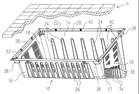
Figure 1 is front perspective illustration of a solar panel support,
illustrating the
invention;
Figure 2 is a rear perspective view of the solar panel support of Figure 1;
Figure 3 is a bottom perspective of the solar panel support of Figure 1;
Figure 4 is a section along line 4-4 of Figure 1, and,
Figure 5 is an enlarged detail of a corner portion showing the abutments.
4
=

CA 02701864 2010-04-21 =
DESCRIPTION OF A SPECIFIC EMBODIMENT
The invention as illustrated generally in Figure 1 the solar panel support
will be
seen to comprise an open top container indicated generally as container (10).
The
container is an integral one piece structure made of moulded thermo plastic
material.
The container (10) will be seen to comprise in this embodiment, a bottom
wall(12, a back wall (14), a front wall ( 16 )and two opposed side walls (18).
The back wall (14) is of a first predetermined height, and the front wall
(16), is
of a second predetermined height. The front wall is lower than the back wall.
As a
result, the upper edges of the side walls (18 ) slope downwardly from the back
wall to
the front wall.
The angle of the slope is calculated in accordance with the desired optimum
angle at which a solar panel (P) will be supported in the particular latitude
for which the
solar panel support is intended to be used. Clearly this will vary somewhat
from one
latitude to another. Around the upper edges of the back wall (14 ) front wall
(16) and
side walls (18 ), there is an outwardly transverse ledge (20), and around the
edge of
the ledge (20 ), there is an upstanding flange (22). The ledge (20) and the
flange (22)
are substantially normal to one another and define an L-shape in section.
The moulding of the solar panel support container (10 ) will normally define
an
angle or draft of the front and back walls and side walls, of approximately in
the region
of 4 degrees, from top to bottom, so as to facilitate removal from a mould.
The back wall (14) incorporates a plurality of generally wedge shaped
depressions (24), extending upwardly from the bottom wall.
Similarly, the front wall (16), has a plurality of generally wedge shaped
5

02701864 2010-04-21 '
=
depressions (26) extending upwardly from the bottom wall.
The bottom wall has a first pair Of parallel transverse grooves, (28 ) formed
from
back to front, and a second pair of parallel grooves (30 ) extending from side
to side
extendingtetWeeri the gtooVest2,8).13iõ4.io A . U;W k
The bottom wall is further defined by a large plurality of dimples or
depressions
(32), which may be generally circular in shape.
Referring now to the to side walls (18 ), these will be seen to be provided
with a
plurality of generally wedge shaped depressions (34), and a plurality of
removable
knock out portions (36). The knock out portions are relatively thinner than
the rest of
the material and may be seleCtively removed as required, for passing
electrical services
through from one support (10 ) to the next.
This will enable the solar panel supports to be positioned side by side in an
array,
and electrical services connecting them can simply be passed from one to
another.
At the upper corners of the front and back walls and side walls, there are
provided
generally rectangular abutments (38). These act as stop portions, so that when
the
solar panel supports are nested one within the other, they do not wedge tight.
= In order to allow for some degree of expansion and contraction of the
solar panel
supports, there are a plurality of spacer elements (40)' positioned in the L-
shaped
spaces defined by the ledge (20) and flange (22). These elements (40) are
relatively
thin and flexible, and allow for a certain degree of expansion and
contraction, without
displacing the solar panels themselves.
Solar panels (P) can be placed in position on the ledges (20), on each solar
panel support (10), and will be retained in position by the flanges (22) and
elements
6

CA 02701864 2010-04-21
=
=
(40).
The supports (10) may simply be weighted internally to hold them in position.
The foregoing is a description of a preferred embodiment of the invention
which is
given here by way of example only. The invention is not to be taken as limited
to any of
the specific features as described, but comprehends all such variations
thereof as come
within the scope of the appended claims.
=
=
1 7

Representative Drawing
A single figure which represents the drawing illustrating the invention.
Administrative Status

For a clearer understanding of the status of the application/patent presented on this page, the site Disclaimer , as well as the definitions for Patent , Administrative Status , Maintenance Fee  and Payment History  should be consulted.

Administrative Status

Title Date
Forecasted Issue Date 2014-04-22
(22) Filed 2010-04-21
Examination Requested 2010-06-29
(41) Open to Public Inspection 2011-10-21
(45) Issued 2014-04-22
Deemed Expired 2018-04-23

Abandonment History

There is no abandonment history.

Payment History

Fee Type Anniversary Year Due Date Amount Paid Paid Date
Application Fee $200.00 2010-04-21
Request for Examination $400.00 2010-06-29
Registration of a document - section 124 $100.00 2010-06-29
Maintenance Fee - Application - New Act 2 2012-04-23 $50.00 2010-06-29
Maintenance Fee - Application - New Act 3 2013-04-22 $50.00 2010-06-29
Maintenance Fee - Application - New Act 4 2014-04-22 $50.00 2010-06-29
Maintenance Fee - Application - New Act 5 2015-04-21 $100.00 2010-08-11
Registration of a document - section 124 $100.00 2011-07-05
Registration of a document - section 124 $100.00 2013-01-18
Final Fee $300.00 2014-02-05
Maintenance Fee - Patent - New Act 6 2016-04-21 $200.00 2016-03-14
Owners on Record

Note: Records showing the ownership history in alphabetical order.

Current Owners on Record
REES, KYLE
Past Owners on Record
REES, KYLE J.
RENEWABLE ENVIRONMENTAL ENERGY SERVICES INC.
SOLAR POWER PRODUCTS INC
Past Owners that do not appear in the "Owners on Record" listing will appear in other documentation within the application.
Documents

To view selected files, please enter reCAPTCHA code :


To view images, click a link in the Document Description column. To download the documents, select one or more checkboxes in the first column and then click the "Download Selected in PDF format (Zip Archive)" or the "Download Selected as Single PDF" button.

List of published and non-published patent-specific documents on the CPD .

If you have any difficulty accessing content, you can call the Client Service Centre at 1-866-997-1936 or send them an e-mail at CIPO Client Service Centre.


Document
Description 
Date
(yyyy-mm-dd) 
Number of pages   Size of Image (KB) 
Abstract 2010-04-21 1 35
Description 2010-04-21 7 265
Claims 2010-04-21 2 50
Cover Page 2011-09-30 1 37
Drawings 2010-06-29 4 190
Abstract 2013-01-04 1 19
Description 2013-01-04 7 245
Representative Drawing 2014-03-26 1 28
Cover Page 2014-03-26 1 56
Assignment 2010-06-29 2 62
Prosecution-Amendment 2010-06-29 1 34
Prosecution-Amendment 2010-06-29 5 221
Assignment 2011-08-10 4 148
Fees 2010-06-29 2 53
Correspondence 2011-04-21 1 15
Correspondence 2011-04-21 1 17
Assignment 2010-04-21 2 93
Correspondence 2011-08-04 1 26
Correspondence 2010-05-31 1 13
Correspondence 2010-06-09 2 90
Fees 2010-08-11 1 34
Correspondence 2010-08-11 3 118
Correspondence 2010-10-07 1 12
Assignment 2010-04-21 3 149
Correspondence 2011-04-13 2 56
Assignment 2011-07-05 3 92
Prosecution-Amendment 2013-01-04 5 165
Prosecution-Amendment 2012-09-05 2 65
Assignment 2013-01-18 3 133
Prosecution-Amendment 2013-12-06 1 46
Correspondence 2014-02-05 1 42
Maintenance Fee Payment 2016-03-14 1 39