Note: Descriptions are shown in the official language in which they were submitted.
CA 02701939 2010-04-07
WO 2009/056790 PCT/GB2008/003400
1
APPARATUS AND METHOD OF MEASURING A LOAD
BACKGROUND
[0001] For many oilfield service operations, numerous chemicals must be used
to
achieve useful production from oil and gas wells, including surfactants,
buffers, acids, bases,
crosslinkers, breakers, etc. For most operations, chemicals are brought to the
location in a
concentrated form and diluted on site to achieve the desired final
concentrations.
[0002] Typically, such liquid chemical concentrates are transported to the
location
of the well via trucks, trailers or skids, including stakebeds, float
trailers, or liquid metering
systems. Due to inaccurate measurement methods and other errors, it is often
necessary to
determine the amount of chemical in a given tank when the tank arrives. In
part because the
well is usually situated in a remote location, no sophisticated technique for
measuring the
quantity of chemical in the tank at the site of the well has been available.
The measurement
has traditionally required field personnel to climb above the tank and use a
long measuring
stick to determine the quantity of chemical in the tank.
[0003] Later, after some of the chemical in the tank has been discharged, it
is
often necessary or desirable to measure the amount of chemical remaining in
the tank. As the
instruments currently used for measuring the rate of discharge of the chemical
from the tank
are not sufficiently accurate, the tank is usually measured again by field
personnel from
above the tank.
[0004] The field personnel required to make these manual measurements are
subjected to significant risks while performing the measurements. Many of the
chemicals
found in the tanks pose health risks, and because the field personnel are
forced to work near
openings in the tanks, they can be exposed to harmful chemicals. The field
personnel also
CA 02701939 2010-04-07
WO 2009/056790 PCT/GB2008/003400
2
face the risk of falling, since manual measurements necessitate their climbing
on top of the
truck, trailer and/or tank.
[0005] In addition to the health and safety hazards attendant to the manual
measuring method, using a measuring stick to determine the amount of chemical
in the tank
results in inherently inaccurate measurements. The measuring stick could be
inserted at a
slight angle and/or slight movements could cause the chemical to splash and
produce an
incorrect reading. Even under ideal conditions, a measuring stick can only be
expected to
determine the quantity of chemical remaining within a significant margin of
error.
[0006] Traditional manual measurements require substantial time as well. Field
personnel must then expend their valuable time by climbing on top of the tank,
carefully
measuring the depth of the chemical and climbing back down. The safety
measures
necessitated by the process consume additional time and human resources.
[0007] Moreover, the roads and access to such oil field locations is often
very
rough. Therefore, it is desirable to have a weighing apparatus that is capable
of providing
reliable and accurate measurements despite adverse conditions.
FIGURES
[0008] Some specific example embodiments of the disclosure may be understood
by referring, in part, to the following description and the accompanying
drawings.
[0009] Figure 1 is a side view of a load measuring apparatus in accordance
with a
first exemplary embodiment of the present invention.
[0010] Figure 2 is a side view of a load measuring apparatus in accordance
with a
second exemplary embodiment of the present invention.
[0011] Figure 3 is a side view of the first exemplary embodiment of the
present
invention depicting the different forces acting on the apparatus when in
operation.
CA 02701939 2010-04-07
WO 2009/056790 PCT/GB2008/003400
3
[0012] Figure 4 is a side view of a third exemplary embodiment of a load
measuring apparatus of the present invention depicting the different forces
acting on the
apparatus when in operation.
[0013] Figure 5 depicts a top view of a load measuring apparatus in accordance
with the third exemplary embodiment of the present invention.
[0014] Figure 6 depicts a perspective view of a load measuring apparatus in
accordance with a fourth exemplary embodiment of the present invention.
[0015] Figure 7 depicts a side view of the forces acting on a load measuring
apparatus in accordance with a fifth exemplary embodiment of the present
invention.
[0016] Figure 8 depicts a side view the forces acting on a load measuring
apparatus in accordance with a sixth exemplary embodiment of the present
invention.
[0017] While embodiments of this disclosure have been depicted and described
and are defined by reference to example embodiments of the disclosure, such
references do
not imply a limitation on the disclosure, and no such limitation is to be
inferred. The subject
matter disclosed is capable of considerable modification, alteration, and
equivalents in form
and function, as will occur to those skilled in the pertinent art and having
the benefit of this
disclosure. The depicted and described embodiments of this disclosure are
examples only,
and not exhaustive of the scope of the disclosure.
SUMMARY
[0018] The present invention is directed to weighing apparatuses and methods.
Specifically, the present invention is directed to systems and methods for
transporting and/or
sensing mass of industrially useful material to identify inventory, mass or
volumetric delivery
rates.
CA 02701939 2010-04-07
WO 2009/056790 PCT/GB2008/003400
4
[0019] In one embodiment, the present invention is directed to a load
measuring
apparatus comprising: a weighing platform; a first lever arm defined by a
first end and a
second end; a second lever arm defined by a first end and a second end; and a
load sensor.
The first ends of the first and the second lever arms are coupled to the
weighing platform and
the second ends of the first and the second lever arms are coupled to the load
sensor.
[0020] In another embodiment, the present invention is directed to a load
measuring apparatus comprising: a weighing platform hinged at a first end; a
load sensor
coupled to the weighing platform; and a support foot coupled to the load
sensor. The load
sensor senses a load applied to the weighing platform.
[0021] In yet another embodiment, the present invention is directed to a load
measuring appratus comprising a framework and at least one load sensors
coupled to the
framework, wherein the load sensor senses a load applied to the framework.
[0022] In another embodiment, the present invention is directed to method of
measuring a load comprising: coupling a weighing platform at a first end to a
first torque
sensor; providing support to a first side of the weighing platform; applying a
load to a second
side of the weighing platform; and using the first torque sensor reading to
determine a value
of the load applied to the weighing platform.
[0023] The features and advantages of the present disclosure will be readily
apparent to those skilled in the art upon a reading of the description of
exemplary
embodiments, which follows.
CA 02701939 2010-04-07
WO 2009/056790 PCT/GB2008/003400
DESCRIPTION
[0024] The present invention is directed to weighing apparatuses and methods.
Specifically, the present invention is directed to systems and methods for
transporting and/or
sensing mass of industrially useful material to identify inventory, mass or
volumetric delivery
rates.
[0025] The details of the present invention will now be discussed with
reference
to the figures. Turning to Figure 1, a load measuring apparatus in accordance
with a first
exemplary embodiment of the present invention is depicted generally by
reference numeral
100. The load measuring apparatus 100 comprises two lever arms 102, 104 each
connected
at one end to corresponding pivotal connections 106, 108. The other end of the
lever arms
102, 104 is in contact with a load sensor 110. In an exemplary embodiment,
load cells are
used as load sensors to determine the force exerted by gravity on an object to
be weighed.
Electronic load cells are preferred for their accuracy and are well known in
the art, but other
types of force-measuring devices may be used. As will be apparent to one
skilled in the art,
however, any type of load-sensing device can be used in place of or in
conjunction with a
load cell. Examples of suitable load-measuring devices include weight-, mass-,
pressure- or
force-measuring devices such as hydraulic load cells, scales, load pins, dual
sheer beam load
cells and pressure transducers. Standard available load cells are available in
various ranges
such as 0-5000 pounds, 0-10000 pounds, etc.
[0026] In one exemplary embodiment, the load sensor is a compressive load cell
110 which is attached at the base and near the center of the weighing platform
112. At least
one support foot 114, 116 is provided at the bottom of each lever arm 102, 104
between the
load cell 110 and the pivotal connections 106, 108 to contact an existing
solid surface such as
a concrete floor, truck bed, frame support, etc (not shown). As would be
appreciated by those
CA 02701939 2010-04-07
WO 2009/056790 PCT/GB2008/003400
6
of ordinary skill in the art, with the benefit of this disclosure, the support
foot may comprise
any component that is used to provide support and is not limited to any
specific shape or
structure. Accordingly, a load effectively applied normal to the weighing
platform 112
surface in the area between the two support feet 114, 116 produces a
proportional force on
the load cell 110 which generates a signal proportional to the applied normal
load.
[0027] In one exemplary embodiment the support feet 114, 116 may be replaced
with pinned supports and the load button at the load cell may be replaced with
a pin
connection. In this embodiment, any loads applied to the weighing platform 112
outside the
pivots produce positive and negative forces that sum to a proportionally
representative force
at the load cell 110 regardless of position.
[0028] Figure 2 depicts a load measuring apparatus in accordance with a second
embodiment of the present invention denoted with reference numeral 200. In the
second
embodiment, the pivotal connections 106, 108 are replaced with deformable
ends. As a
result, the weighing platform 212 and the lever arms 202, 204 form a single
piece, resting on
support feet 214, 216.
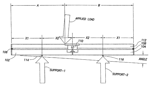
[0029] A better understanding of operation of an embodiment of the present
invention may be obtained by turning to Figure 3. As depicted in Figure 3, the
distance
between each of the support feet 114, 116 and the corresponding pivotal
connection 106, 108
is labeled "XI" and the distance between each support foot 114, 116 and the
load cell 110 is
labeled as "X2". Similarly, the distance between the point of application of
the load and a
first pivotal connection 106 is labeled "A" and the distance between the point
of application
of the load and a second pivotal connection 108 is labeled "B". Finally, the
deviation of the
weighing platform 112 and lever arms 102, 104 from the level axis is denoted
as "Angle". A
mechanical analysis of the invention in which the load is assumed to be
applied between the
CA 02701939 2010-04-07
WO 2009/056790 PCT/GB2008/003400
7
support feet demonstrates that the resulting force on the load cell 110 can be
calculated with
the following equation:
Force Load Cell = Applied Load x {2 x XI/(A+B) xCos (Angle)}
[0030] As would be appreciated by those of ordinary skill in the art, with the
benefit of this disclosure, the force at the load cell 110 is independent of
the point of
application of the load on the platform between the supports. Moreover, the
error from any
slope is equivalent to the ratio of the cosine of the angle of the weighing
platform 112 from
the level axis and the equation above accounts for any such errors.
[0031] In one exemplary embodiment a tilt sensor may be included to correct
the
errors resulting from deviations of the weighing apparatus from the level
axis. In another
exemplary embodiment, it may be appropriate to use a means to approximately
level the
weighing platform 112 rather than add a tilt sensor. However, as would be
appreciated by
those of ordinary skill in the art, with the benefit of this disclosure, the
error is less than 0.5%
for angles of less than 5 degrees. Because the resulting error is often
minute, in many
applications no angle sensor is required.
[0032] In a load measuring apparatus in accordance with an embodiment of the
present invention the load sensor 110 and pivotal connections 106, 108 are
attached to the
weighing platform 112 and the load is transmitted to the lever arms 102, 104
via the support
feet 114, 116. As a result, the position of the support feet 114, 116
determines the ratio of the
load applied to the weighing platform 112 to force applied to the load cell
110.
Consequently, the support feet 114, 116 may be designed to be adjustable in
order to allow a
variation of the capacity or resolution of the load measuring apparatus. As a
result, the ability
to adjust the support feet enables the use of a single capacity sensor for
multiple ranges which
can produce higher resolution at lower loads or greater range and lower
resolution at larger
CA 02701939 2010-04-07
WO 2009/056790 PCT/GB2008/003400
8
loads. Additionally, adjustable support feet define the point of load
application, enable
mechanical ranging of the sensor and eliminate the requirement for a base
plate. These
improvements reduce the weight, profile height and manufacturing costs of the
load
measuring apparatus while raising the electronic sensing components above any
materials or
liquids that may accumulate beneath the platform to provide improved overall
reliability.
[0033] A load measuring apparatus may be used to transport containers filled
with
material that is industrially useful to oil field locations. In one exemplary
embodiment a
transport locking mechanism (not shown) may be provided to protect the load
sensor from
extreme shock loads during transportation. The lock would carry the loads
between the
weighing platform 112 and the lever arms 102, 104 in place of the load sensor.
Consequently, the lock would lift and hold the load sensor off the lever arms
102, 104
thereby preventing contact between the load cell 110 and the lever arms 102,
104. The lock
may then be disengaged upon arrival at the destination to allow contact
between the lever
arms 102, 104 and the load cell 110.
[0034] In other exemplary embodiments, tie down hooks, straps or similar
features (not shown) may be added to the invention to hold down the containers
being
transported or hold the support feet 114, 116 in place on a truck, ship, train
or other surface
without influencing the weight sensing accuracy or ability to measure loads.
As would be
appreciated by those of ordinary skill in the art, with the benefit of this
disclosure, other
isolation methods and materials may be utilized in all or any part of the
weighing apparatus
assembly disclosed herein to reduce stresses and increase reliability. Because
such methods
and materials are known to those skilled in shock and vibration isolation
design and do not
change the concept of the present invention, they will not be discussed in
detail.
CA 02701939 2010-04-07
WO 2009/056790 PCT/GB2008/003400
9
[0035] Figure 4 depicts a third embodiment of the present invention shown
generally with reference numeral 400. In this exemplary embodiment, the load
cell 410 is
located on one side and a hinge 420 is located on the opposite side of the
weighing platform
412. The distance from the load cell 410 to the hinge 420 is labeled "L", the
distance
between an applied load "Fy" and the hinge 420 is labeled "X" and the angle of
the weighing
platform 412 from the level is labeled "a". As would be appreciated by those
of ordinary
skill in the art, with the benefit of this disclosure, when a load Fy is
applied to the weighing
platform 412, the force R2 at the load cell 410 can be calculated using the
following
equation:
R2 = Fy x Cos (a) x X/L
[0036] As would be appreciated by those of ordinary skill in the art, with the
benefit of this disclosure, in one exemplary embodiment, the weighing platform
412 may be a
tanker trailer. In this exemplary embodiment, the load cell 410 may be
installed in one of a
tanker trailer axle or a truck fifth wheel. Moreover, the tanker trailer axle
or the truck fifth
wheel may operate as the hinge 420.
[0037] Figure 5 depicts a top view of the third exemplary embodiment of the
weighing apparatus which includes a lifting device 510 for setting road feet
520 which
support the frame 530 during transport so that no shock loads are applied to
the load cell 540
while the unit is in transport mode. Specifically, when in transport mode, the
lifting device
510 lifts the frame 530 which is hinged at the support feet 550. The load
measuring
apparatus will then rest on the setting road feet 520. This embodiment is
sensitive to the load
position and changes in the angles influence the effective load position by
shifting the center
of the mass. As would be appreciated by those of ordinary skill in the art,
with the benefit of
CA 02701939 2010-04-07
WO 2009/056790 PCT/GB2008/003400
this disclosure, these errors can be corrected by mathematical models that are
incorporated
into a processor in the weight display.
[0038] Figure 6 depicts a fourth exemplary embodiment of the present invention
shown generally with reference numeral 600. In this embodiment two load cells
610, 620 are
used to sense the entire load. As would be appreciated by those of ordinary
skill in the art,
with the benefit of this disclosure, more than two load cells may be used in a
similar
arrangement to sense the weight on the load measuring apparatus. The frame 630
holding the
materials to be weighed is placed in contact with the load cells 610, 620.
[0039] The load cells 610, 620 are arranged in a symmetrical pattern to reduce
sensitivity to the position of the load for precision measurements. When
multiple weighing
devices are used, they may be arranged specifically to counter any undesired
forces or
moments that may cause the weighing apparatus to report an inaccurate weight.
In particular,
the weighing devices should be arranged in a symmetrical configuration such
that for each
load cell affected by the undesired force, another load cell produces an
opposite response.
When the forces measured by the weighing devices are summed to determine the
total
weight, the impact of the undesired force will be reduced or cancelled out by
the equal and
opposite measurements of the force by separate weighing devices.
[0040] Figure 7 shows a fifth exemplary embodiment of the present invention
depicted generally with reference numeral 700. The load measurement apparatus
700 is
similar to the embodiment depicted in Figure 4 except that the load cell 410
and pivot 420
have been replaced with a torque sensor 710. The torque sensor 710 restrains
rotation at the
pivot and senses the amount of torque applied at the connection. When a load
"Fy"
is applied at a distance "X" from the torque sensor 710 on the weighing
platform 715 and the
CA 02701939 2010-04-07
WO 2009/056790 PCT/GB2008/003400
11
weighing platform 715 is at an angle, "a", from the level axis, the amount of
torque, "T", is
determined by the following equation:
T = Fy x X x Cos (a)
As a result, once the amount of torque sensed by the torque sensor is known,
the amount of
load, FY, may be determined using the following equation :
Fy = T / (X x Cos(a))
[0041] Similarly, Figure 8 depicts a sixth exemplary embodiment of the present
invention 800 similar to that shown in Figure 1 except that the load cell 110
and pivotal
connections 106, 108 have been replaced with torque sensors 810, 815. The
torque sensors
810, 815 restrain rotation at the pivotal connections and sense the amount of
torque applied at
the connections. In this exemplary embodiment 800 the torque is caused by the
support feet
820, 825 which are located at a distance "X" from the torque sensors 810, 815
resisting the
force "Fy" applied to the weighing platform 830. The torque, "T", at each
sensor is
proportional to the length (X) of the lever from torque sensor to support foot
and the total
torque, "ET", is representative of the total force applied. The total torque
can then be
calculated with the following equation:
ET=TRight+TLeft=FyxXx Cos (a)
Therefore, once the total amount of torque, E T, sensed by the torque sensor
is known, the
applied load, Fy, can be determined using the following equation:
Fy = E T/(X x Cos (a))
[0042] In one exemplary embodiment, the storage units and the load measuring
apparatus are attached to a vehicle. Alternatively, the storage units may not
be fixed to the
vehicle, in which case the load measuring apparatus may be attached to the
trailer, may be
attached to the storage units, may be integrated into a cradle which holds the
tank mounted on
CA 02701939 2010-04-07
WO 2009/056790 PCT/GB2008/003400
12
the vehicle, or may be mobile and able to be moved into various configurations
depending on
the needs of a particular shipment. In yet another embodiment, the load
measuring apparatus
may be attached to one or more mobile pallets or scales. The storage units may
then be
placed on the pallets when loaded in the vehicle.
[0043] While the load and degree of deviation measurements contemplated by the
present invention may be taken manually, an automatic means of processing the
information
generated by the measurement devices is desirable. In one embodiment, a
computer system
is electrically coupled to the load measuring apparatus and/or the level
measuring devices and
receives electronic signals from those devices. In another embodiment the
signals may be
filtered to reduce noise using hardware or software in the computer system or
before the
signal is fed into the computer system. The computer system can be configured
to
automatically perform calculations to compensate for off-axis forces or
moments and the
degree of deviation from the level position.
[0044] The computer system may also be configured to record multiple weight
measurements over a given period of time. The computer system may then be used
to
calculate the rate of discharge by, for example, dividing the difference of
any two weight
measurements by the time elapsed between the measurements. In some
embodiments, the
computer system will further be operable to compare the calculated discharge
rate with the
desired discharge rate and to automatically increase or decrease the actual
discharge rate by
communicating with or otherwise manipulating the discharge control mechanism.
By
performing this adjustment substantially in real-time, the accuracy of the
actual discharge rate
is enhanced.
[0045] A computer system adds further functionality in contexts, such as well
service operations, where the substance contained in the storage unit is to be
mixed with
CA 02701939 2010-04-07
WO 2009/056790 PCT/GB2008/003400
13
another substance in a specified ratio. The computer system may monitor the
weights and
discharge rates of multiple storage units and be operable to adjust the
discharge rates (via
multiple discharge control mechanisms) to conform to a series of predefined or
user-specified
ratios. The increased accuracy of the weight-based system disclosed herein
facilitates closer
adherence to the desired ratios, especially when the discharge rates are
adjusted substantially
in real-time.
[0046] Although the present invention is described with relation to oil field
applications, as would be appreciated by those of ordinary skill in the art,
with the benefit of
this disclosure, the apparatus and methods described herein may be used in any
other
application where it would be desirable to measure the weight of a substance.
The present
invention could easily be adapted for any industrially useful substance,
including liquids, dry
materials, slurries, solutions or suspensions. In another embodiment, for
example, the storage
units being weighed may contain dry gel polymer. The dry gel polymer may also
be used as
an additive during a well service operation, but the present invention is not
limited to
chemical inventory management in well service operations. The present
invention may be
applied in any circumstance when the weight, mass, volume or rate of discharge
of an
industrially useful substance is desired, especially when the measurement must
be taken at a
remote location. The present invention may also be adapted to accommodate
mixtures such
as cement or granular substances such as sand.
[0047] Moreover, as would be appreciated by those of ordinary skill in the
art,
with the benefit of this disclosure, each embodiment of the present invention
may also
include temperature, angle, fluid density and fluid level sensors in order to
correct
environmental factors that may influence accuracy and/or to establish the
volume of fluid that
is contained and/or delivered. Additionally, each embodiment of the present
invention may
CA 02701939 2010-04-07
WO 2009/056790 PCT/GB2008/003400
14
include roading supports or locks to eliminate shock loads from damaging the
transducers,
load bars, strain gauges or other load sensors used to convert the mass to an
electrical signal.