Note: Descriptions are shown in the official language in which they were submitted.
CA 02702254 2009-12-14
WO 2008/151375 PCT/AU2008/000847
FUEL DISPENSING
FIELD OF THE INVENTION
This invention relates to a method and apparatus for fuel dispensing together
with
ancillary actions. It is particularly related to dispensing blended fuels but
is not
limited to such.
BACKGROUND
Service stations that sell petrol (or gasoline) are widespread throughout each
country
and fundamentally comprise inground tanks of each separately required fuel or
mixture of fuel connected directly to each separate required bowler.
However due to the increase in oil prices the cost of petrol has dramatically
increased
and other options are being considered. Apart from diesel there are other
fundamental
choices of fuel including biodiesel and other biofuels which are sourced from
replaceable organically grown product rather than from irreplaceable oil
reserves.
Since there are variations in the science or marketing or simply acceptance of
the use
of biofuels, the consumer generally uses different combinations depending on
the
knowledge or acceptance of the user. The environmental sensitivity of the
location of
use can also affect the required different ratios of mixtures of biofuels to
normal fuels
that will be used.
In the present fuel dispensing systems at petrol stations and service stations
such
variations are not really available and therefore the choice to the consumer
is
dramatically limited to the chosen fuels or mixtures provided by the supplier.
In this
market of consumer choice and individual decisions on how to be more
environmentally considerate, this limitation is not acceptable.
It is therefore an object of the invention to provide a system and means that
facilitates
provision of choice of mixtures of fuels to the consumer.
CA 02702254 2009-12-14
WO 2008/151375 PCT/AU2008/000847
SUMMARY OF THE INVENTION
In accordance with the invention there is provided a fuel dispensing means for
dispensing a batch of fuel at a requested mixture of two fuels including
providing a
means for metered mixture of the two fuels by metering two separate fuels for
combination in a mixing chamber and for substantially homogenising the
combined
fuels, and a dispensing means for directly dispensing the batch of homogenised
combined fuels at the requested mixture.
The mixing chamber can include a positive displacement means for displacing
the
combined fuels to the dispensing means.
The mixing chamber can have a predetermined volume that is greater than
expected
maximum tank delivery in a single dispensing occurrence.
The mixing means can include a flow means for causing homogenising of the
combined fuels.
The flow means can be static and rely on the effected flow to cause the
homogenising
of the combined fuels.
The dispensing means can include a pump for pumping the homogenised combined
fuels to a vehicle tank.
The pump of the dispensing means can coordinate with the positive displacement
means of the mixing chamber to provide the dispensing.
The control of the dispensing can be provided by the dispensing means
including an
activation means at the nozzle that must engage the tank opening of the
vehicle to
begin dispensing.
The invention also provides a fuel dispensing system including a plurality of
bowsers
for dispensing one of a plurality of different fuels, wherein at least one of
the bowsers
is connected to fuel dispensing means leading from a plurality of fuel tanks
for
2
CA 02702254 2009-12-14
WO 2008/151375 PCT/AU2008/000847
providing a metered mixture of two fuels including providing metering means
for
metering two separate fuels for combination in a mixing chamber, a mixing
means for
substantially homogenising the combined fuels and a dispensing means for
dispensing
the homogenised combined fuels through the bowser.
A fuel dispensing system including a plurality of tanks for connection to a
plurality of
bowsers wherein the plurality of tanks are connected to a dispensing system
providing
a method of fuel dispensing of at least two fuels including providing metering
means
for metering two separate fuels for combination in a mixing chamber which
substantially homogenises the combined fuels and a dispensing means for
dispensing
the homogenised combined fuels; wherein the plurality of fuels provided or
mixtures
provided is greater than the number of plurality of tanks provided.
The invention also provides a removable dispensing station for dispensing
multiple
fuels such that a station can be readily located at a required site but if for
commercial
or other reasons can be readily moved to a different location without the need
for
substantial excavation and rebuilding and decontamination of soil as required
with
usual petrol stations or service stations. The dispensing station of the
invention
including
a) a plurality of stand alone tanks each for containing a fuel;
b) a first protection means surrounding each of the plurality of tanks;
c) a second protection means for at least circumferentially
surrounding the first protection means and
d) a third protection means for circumferentially surrounding the
second protection means
wherein the second protection means is an assembly with detachably
connecting parts that forms a frame structure for locating and supporting the
first and third protection means to form a demountable and removable
multiwall bander for protecting the fuel tanks and safeguarding the users from
accidental explosions.
The tanks can be vented vertically so as to provide a directional access and
explosion
or combustion directional release.
3
CA 02702254 2009-12-14
WO 2008/151375 PCT/AU2008/000847
The first protection means are solid mass blocks which can be orientated and
locked
into position by the second protection means. The third protection means
performs a
dual function such as vending machines and are mounted to the second
protection
means on an outer side.
The removable dispensing station can perform its I`unetion also by the
plurality of
tanks each for containing a fuel being connected to a fuel dispensing means
whereby
the removable dispensing station can dispense a plurality of fuels or fuel
mixtures
greater than the number of fuel tanks.
Therefore it can be seen that the invention provides a novel method of fuel
dispensing
by providing a removable structure including a first plurality of above ground
standalone tanks that allows for storage of a first plurality of different
fuels and a
multiwall barrier for protecting the first plurality of above ground
standalone tanks
wherein at least one of the wall barriers of the multiwall barrier provides a
dismountable supporting means for at least one other of the wall barriers. In
this way
the location of the dispensing station is readily movable but when constructed
in this
novel way provides a safe and acceptable multifunctional fuel dispensing
station that
meets all the safety requirements and can be readily controlled in operation
remotely.
Further it provides a fuel dispensing means that dispenses a batch of at least
two fuels
blended on site and including metering means including batch receiving tank
for
metering two separate fuels for combination in a mixing chamber which
substantially
homogenises the combined fuels and a dispensing means for dispensing the
substantially homogenised combined fuels wherein the plurality of fuels
provided or
mixtures provided is greater than the number of plurality of tanks provided.
In this
way the sizing of the dispensing station can be retained at reasonable size
that will
therefore also allow ready deinstallation and reinstalllation at new location.
Further it
allows fuel dispensing station to be located at otherwise impossibly small
locations if
a plurality of fuels or blended fuels are required. This even extends to use
on
platforms or barges. Even more importantly it allows the consumer to have
choice.
4
CA 02702254 2009-12-14
WO 2008/151375 PCT/AU2008/000847
BRIEF DESCRIPTION OF THE DRAWINGS
In order that the invention is more readily understood an embodiment will be
described by way of illustration only with reference to the drawings wherein:
Figure 1 is a diagrammatic perspective view of a fuel dispensing station in
accordance with an embodiment of the invention;
Figure 2 is an overhead plan view of the fuel dispensing station of figure 1;
Figure 3 is the overhead plan view of the second embodiment of a fuel
dispensing station in accordance with the invention;
Figure 4 is an overhead plan view of a third embodiment of a fuel dispensing
station in accordance with invention;
Figure 5 is an overhead plan view of a fourth embodiment of a fuel dispensing
station in accordance with invention in which it is mounted on a platform for
dispensing fuels to boats on the water;
Figure 6 is a diagrammatic view of a means for utilising a method of fuel
dispensing of a plurality of fuels in accordance with the invention.
EMBODIMENT OF THE INVENTION
Referring to the drawings in Figure 1 and 2, there is shown a fuel dispensing
station
11 in accordance with the invention that is to be unmanned. To undertake this
action,
to meet the safety requirements, to supply a range of different choices of
fuel or
mixtures of fuels, and to meet the metering requirements for tax excise, a
number of
problems needed to be overcome. Further, to provide a dispensing station that
can be
readily packed up and moved to a new location due to commercial reasons
without the
costs and troubles in excavation and removal of inground tanks and the months
of gas
retrieval and soil reclamation for removing contaminated soil from oil leaks
also
required a new approach.
The dispensing station 11 includes a plurality of bowsers for dispensing one
of a
plurality of different fuels, wherein at least one of the bowsers includes a
method of
fuel dispensing a metered mixture of two fuels. Generally fuels can include
the
following:
i. petrol (gasoline)
5
CA 02702254 2009-12-14
WO 2008/151375 PCT/AU2008/000847
ii. ethanol or other biofuel
iii, diesel
iv. biodiesel
Y. any combination of petrol and ethanol but usually 5% ethanol and 10%
ethanol
vi, any combination of diesel and biodiesel but usually 5% biodiesel, 10%
biodiesel, 100% biodiesel.
The method provides metering means for metering two separate fuels for
combination
in a mixing chamber, a mixing means for substantially homogenising the
combined
fuels and a dispensing means for dispensing the homogenised combined fuels.
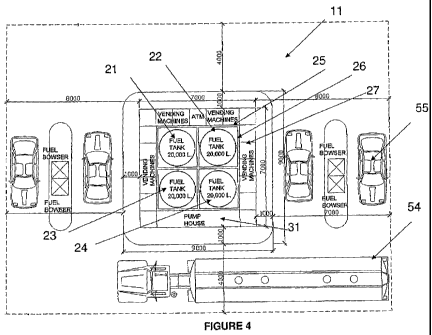
With regard to Figures 3 and 4 there is shown a dispensing station for
dispensing fuel.
This can be a removable dispensing station with ability for dispensing
multiple fuels.
A plurality of stand alone tanks 21, 22, 23, 24 each for containing a fuel are
located in
a central position with a first protection means surrounding each of the
plurality of
tanks. This first protection means 25 is generally a solid, mass structure in
the form
of prefabricated blocks such as reinforced concrete that can be stacked and
secured
around each fuel tank, Due to this first circumferential means around each
tank then
the tanks containing flammable liquids 21, 22 including petrol or ethanol can
be
stored adjacent the tanks 23, 24 containing combustible liquids including
diesel and
biodiesel.
A second protection means 26 is in the form of steel for at least
circumferentially
surrounding the first protection means 25 and with detachably connecting parts
that
forms a frame structure for locating and supporting the first protection
means.
A third protection means 27 which includes a bank of articles that perform a
secondary function such as vending machines, Automatic Teller Machine (ATM)
and
pump house circumferentially surrounds the second protection means and are
fixed
thereto to locate this bank of articles. However the third protection means
adds
another layer of safety protection.
6
CA 02702254 2009-12-14
WO 2008/151375 PCT/AU2008/000847
By the interconnection there is formed a demountable and removable multiwall
barrier 25, 26, 27 for protecting the fuel tanks 21, 22, 23, 24 and
safeguarding the
users from accidental explosions. The tanks are vented vertically but have
security
access restricting coverage and any signage as required.
However to allow the ready dispensing the removable dispensing station can
minimise
the number of the plurality of tanks each for containing a fuel by making use
of the
fuel dispensing means whereby the removable dispensing station can dispense a
plurality of fuels or fuel mixtures greater than the number of fuel tanks.
Rel:erring to Figure 4 there is shown a fuel dispensing system including a
plurality of
tanks for connection to a plurality of bowsers wherein the plurality of tanks
are
connected to a dispensing system providing a method of fuel dispensing of at
least
two fuels including providing metering means for metering two separate fuels
for
combination in a mixing chamber which substantially homogenises the combined
fuels and a dispensing means for dispensing the homogenised combined fuels;
wherein the plurality of fuels provided or mixtures provided is greater than
the
number of plurality of tanks provided.
Referring to Figure 5, due to the above ground and removable structure the
fuel
dispensing means can be constructed on a barge or platform and provide
dispensing of
blended fuels directly to boats. In this tight environment the choice of
required ratio
of blended fuels is finally available, which has never been possible before.
It should
be noted that if access to a side of the construction is not possible then the
fuel tanks
can be vented sideways outwardly as well to the secured non accessible side.
In Figure 6 there is shown the method of fuel dispensing including providing a
metered mixture of two fuels. A metering means 51, 52 for metering two
separate
fuels for combination in a batch chamber 62 that is fed to a mixing chamber 63
by a
piston pump 61. The mixing chamber 63 includes inline static mixer elements
such
that the positive displacement of fuel from the batch chamber 62 by means of
the
piston pump 61 for displacing the combined fuels to the dispensing means for
substantially homogenising the combined fuels, The dispensing means includes
7
CA 02702254 2009-12-14
WO 2008/151375 PCT/AU2008/000847
dedicated line 64 from the mixing chamber to pump 65 connected to bowsers 66
for
dispensing the homogenised combined fuels to a vehicle 55.
The dispensing means pump for pumping the homogenised combined fuels to a
vehicle tank and the positive displacement pump coordinate so as to be able to
dispense batch amounts from the batch chamber at the required mixture level.
The control of the dispensing can be provided by the dispensing means
including an
activation means at the nozzle that must engage the tank opening of the
vehicle to
begin dispensing.
In another improvement of the system a fuel tanker 51 can arrive at the
dispensing
station I I and empty its partial load into a batch tank which is connected to
a
dispensing means that can receive fuels from any one of the plurality of tanks
21, 22,
23, 24 and provide the required mixture ratio of fuels back to the fuel
tanker. For
example the tanker might have a load of diesel at 100% but for delivery to
next
location requires a 80/20 ratio of diesel to biodicsel. Instead of returning
to base the
tanker can use the dispensing station to provide the required mixture with its
own
diesel by delivery to the batch tank and mixture through the dispensing means
at the
required ration by inclusion of biodiesel from the biodiesel tank and return
to the
tanker. The need to not have to return to base but to have blended homogenised
fuel
at the required ratio is a significant advantage of the new system due to its
novel
construction and operation.
It should be understood that the above description is of a preferred
embodiment and
included as illustration only. It is not limiting of the invention. Clearly
variations of
the method of fuel dispensing and means therefore would be understood by a
person
skilled in the art without any inventiveness and such variations are included
within the
scope of this invention as defined in the following claims.
8