Note: Descriptions are shown in the official language in which they were submitted.
CA 02702495 2010-04-09
WO 2009/051936
PCT/US2008/077219
METHODS AND APPARATUS TO CHANGE THE MOBILITY OF FORMATION
FLUIDS USING THERMAL AND NON-THERMAL STIMULATION
FIELD OF THE DISCLOSURE
[0001] This disclosure relates generally to changing the mobility of
formation
fluids and, more specifically, to changing the mobility of formation fluids
using both
thermal and non-thermal stimulation.
BACKGROUND
[0001] As global reserves of light crude oil diminish, the exploration for
and
production of heavy oil and bitumen becomes of increased importance to
maintain a
stable global supply of hydrocarbon. When evaluating heavy oil or bitumen
formations, it is advantageous to obtain representative samples of the
formation to
determine appropriate drilling and production methods. However, due to the
mobility
of heavy oil and bitumen, sampling these formations can be difficult or
impossible
using many known light crude oil sampling techniques.
[0002] Attempting to sample a heavy oil or bitumen, for example, without
first
increasing the mobility of these fluids can result in excessive drawdown
pressures,
which can cause failure of a pump or pumpout unit being used to extract the
fluid,
failure (e.g., cracking, fracturing and/or collapse) of the formation, and/or
phase
changes and, thus, compositional changes to the fluid being sampled. Further,
such
excessive drawdown pressures can lead to the production of sand, which may
cause
failure of sampling tool seals. While increasing the areas of the sampling
ports or
probes can reduce the drawdown pressures, larger port or probe areas can be
difficult
to achieve without adversely impacting the size of the sampling tool and the
ability to
achieve an effective seal around the sampling ports or probes.
- 1 -
WO 2009/051936 CA 02702495 2010-04-09
PCT/US2008/077219
[0003] One factor contributing to the low mobility of heavy oil and
bitumen
formation is the high viscosity of these fluids. As illustrated by Equation 1
below, a
flow-rate of fluid from a subsurface formation may be changed by increasing a
pressure difference, changing the permeability of the formation or by
decreasing the
viscosity of the formation fluid. The pressure difference applied by the
sampling tool
to withdraw the fluid is represented by Ap, the fluid viscosity is represented
by 77 and
the permeability of the formation is represented by k.
[0004] Equation 1 Q ck Ap = k I 77
[0005] Substantially reducing the viscosity of the heavy oil and
bitumen in a
formation can increase mobility sufficiently to obtain a sample. However, to
be
helpful in determining a production strategy, the fluid sample has to be
representative
of the formation fluid and/or any changes to the characteristics of the fluid
sample
have to be reversible.
[0006] Some known methods to increase the mobility of formation
fluids involve
heating the formation through a variety of means (e.g., thermal stimulation),
or
injecting a diluent into the formation (e.g., non-thermal stimulation). The
diluent or
solvent is usually miscible with the formation fluid, and in these cases, the
diluent
may be referred to as a solvent. However, steam or water may not be readily
miscible
diluents. Production methods that rely on injecting a suitable solvent into a
formation
include vapor assisted extraction (VAPEX). Another primary production method
is
cold heavy oil production with sand (CHOPS) that relies on reducing the
pressure and
evolving the gas from the formation to produce a foam. Some example methods of
heating a formation include cyclic steam circulation, steam floods, and steam
assisted
gravity drainage (SAGD). While the use of some diluents may be appropriate for
- 2 -
CA 02702495 2012-04-24
54430-51
certain applications such as, for example, production in which the chemical
composition and/or the physical properties of the formation fluid need not be
maintained, these diluents may not be appropriate to obtain samples of
formation
fluid because they irreversibly change the formation fluid.
[0007] While the above-mentioned methods may be used to change the
mobility of a formation fluid, in some circumstances, the mobility of the
formation fluid
is not sufficiently increased by either heating the formation fluid or
injecting a diluent
into the formation fluid.
SUMMARY
According to an aspect of the present invention, there is provided a
subsurface formation fluid mobility changing apparatus, comprising: a
container
configured to hold a reactant; a reactor configured to initiate a chemical
reaction with
the reactant; an injector configured to inject a product of the chemical
reaction into a
subsurface formation, wherein the product of the chemical reaction comprises
heat
and a gaseous diluent operable to change a mobility of a fluid in the
formation; and a
controller configured to control at least one of the reactor or the injector.
According to another aspect of the present invention, there is provided
a method of changing a subsurface formation fluid mobility, comprising:
initiating a
chemical reaction with one or more chemicals, wherein a product of the
chemical
reaction comprises heat and a gaseous diluent; exposing the product of the
chemical
reaction to the formation to change the mobility of a formation fluid; and
obtaining a
sample of the formation fluid after exposing the product of the chemical
reaction to
the formation.
[0008] A disclosed example provides an example apparatus to simultaneously
provide thermal and non-thermal stimulation to change a mobility of a fluid in
a
subsurface formation. The apparatus includes one or more containers to hold
one or
more reactants. Additionally, the apparatus includes a reactor to initiate a
chemical
reaction with at least one of the reactants. Further, the apparatus includes
3
CA 02702495 2012-04-24
54430-51
an injector to inject a product of the chemical reaction into a formation. The
product
of the chemical reaction comprises heat and a gaseous diluent to change a
mobility
of a formation fluid. Still further, the apparatus includes a controller to
control at least
one of the reactor, or the injector.
[0009] Another disclosed example provides an example method to
simultaneously provide thermal and non-thermal stimulation to change a
mobility of a
fluid in a subsurface formation. The method includes initiating a chemical
reaction
with one or more chemicals. A product of the chemical reaction comprises heat
and
a gaseous diluent. Additionally, the method includes exposing the product of
the
chemical reaction to the formation to change the mobility of the formation
fluid.
3a
=
WO 2009/051936 CA 02702495 2010-04-09
PCT/US2008/077219
BRIEF DESCRIPTION OF THE DRAWINGS
[0002] FIG.1 depicts a graph that illustrates a known relationship
between a
viscosity of a formation fluid and a temperature of a formation fluid.
[0003] FIG. 2 depicts an example wireline tool that may be used to
change the
mobility of a formation fluid and to extract and analyze formation fluid
samples.
[0004] FIG. 3 depicts a block diagram of an example apparatus that may
be used
to implement a formation tester of the example wireline tool of FIG. 2 to
change the
mobility of a formation fluid and to extract and analyze formation fluid
samples.
[0005] FIG. 4 depicts a block diagram of an example apparatus that may
be
implemented in connection with the example apparatus of FIG. 3.
[0006] FIG. 5 depicts a block diagram of another example apparatus
that may be
implemented in connection with the example apparatus of FIG. 3.
[0007] FIG. 6 depicts a flow diagram of an example method that may be
used to
change the mobility of a formation fluid and to extract and analyze formation
fluid
samples.
DETAILED DESCRIPTION
[0008] Certain examples are shown in the above-identified figures and
described
in detail below. In describing these examples, like or identical reference
numbers are
used to identify the same or similar elements. The figures are not necessarily
to scale
and certain features and certain views of the figures may be shown exaggerated
in
scale or in schematic for clarity and/or conciseness. Additionally, several
examples
have been described throughout this specification. Any features from any
example
may be included with, a replacement for, or otherwise combined with other
features
from other examples.
- 4 -
CA 02702495 2010-04-09
WO 2009/051936
PCT/US2008/077219
[0009] FIG. 1 is a graph 100 that is representative of testing done on
an Oman
crude oil (e.g., the Mukhaizna formation) at temperatures ranging between 30 C
and
100 C as described in Shigemoto et. al., Energy Fuels 2006, 20, 2504-2508 and
incorporated herein by reference. The graph 100 includes an abscissa 102 and
an
ordinate 104. The abscissa 102 illustrates the temperature at which the
formation
fluid sample was tested and the ordinate 104 is representative of the
kinematic
viscosity of the formation fluid sample. The measured data is illustrated by a
curve
106 and may be represented by Equation 2 below, where the formation fluid
viscosity
i is represented as a function of temperature t, and a coefficient a =
6871.682 K-1 and
a coefficient b = -13.9693. The functional form of equation 2 was recommended
by
Vogel, The law of the relation between the viscosity of liquids and the
temperature
Physik Z. 1921, 22, 645-646 which is incorporated herein by reference. The
curve
106 illustrates that increasing the temperature 100 C above the reservoir
temperature
reduces the viscosity by a factor of approximately 100.
77/ cP = exp { a + b}
[0010] Equation 2 (T I K)
[0011] As described in Quail et al., Ind. Eng. Chem. Res. 1988, 27, 519-
523,
which is incorporated herein by reference, the solubility, viscosity and
density of 59
heavy crude oil samples taken from Saskatchewan, Canada were expressed as a
function of the concentration of carbon dioxide at temperatures between 293K
and
413K at pressures ranging between 0.1 MPa and 14 MPa. The results of these
measurements indicated that the viscosity of the formation fluid decreased at
a
substantially constant temperature with increasing carbon dioxide
concentration
within the formation fluid.
- 5 -
WO 2009/051936 CA 02702495 2010-04-09
PCT/US2008/077219
[0012] A mobility of formation fluid may be changed by non-thermal
stimulation
or thermal stimulation. To change the mobility of a formation fluid using non-
thermal
stimulation involves injecting into a formation fluid a diluent or solvent
that may or
may not be miscible with the formation fluid and which increases the mobility
of the
formation fluid by decreasing its viscosity. Examples of non-thermal
stimulation
have been described in Kokal et al., S. G. Phase Behavior Correlation of
CO2/Heavy
Oil Mixtures For Enhanced Oil Recovery. Fluid Phase Equilib. 1989, 52, 283-290
and Mehrotra, et al., Data and correlation for CO2-Peace River Bitumen Phase
Behaviour at 22-200 C. AOSTRA J. Res. 1989, 5, 351-358. These materials
describe
decreasing the viscosity of the formation fluid by a factor of approximately
60 by
injecting carbon dioxide into a formation fluid up to its solubility limit.
For example,
the viscosity of a formation fluid having a viscosity of approximately 2000 cP
at
reservoir conditions (e.g., down-hole conditions) can be decreased to about 30
cP. To
decrease the viscosity of 1 liter (L) of formation fluid in this manner
requires about 2
liters of carbon dioxide at a pressure of approximately 20 kpsi to be injected
into the
formation. Alternatively, natural gas and/or mixtures of nitrogen and carbon
dioxide
may be injected into a formation to reduce the viscosity of a formation fluid.
However, the decrease in viscosity may be less compared to the example above
involving the injection of carbon dioxide.
[0013] Another example of non-thermal stimulation involves injecting
hydrogen
into a formation. Such a process has been recognized by the Shell Oil Company,
which has sponsored measurements of phase equilibira of hydrogen with heavy
oil
components at the Delft University of Technology. Hydrogen is relatively
soluble in
hydrocarbons (e.g., formation fluid) and, if injected into a formation fluid,
may be
later removed using a process called vacuum sublimation. However, if hydrogen
is
- 6 -
WO 2009/051936 CA 02702495 2010-04-09
PCT/US2008/077219
injected into a formation fluid at an elevated temperature, a reaction (e.g.,
hydrothermolysis) may occur that causes an irreversible alteration of the
chemical
composition of the fluid sample, which is not desirable when obtaining a
formation
fluid sample. To substantially prevent this type of reaction from occurring
between
the hydrogen and the formation fluid, the temperature at which the hydrogen is
exposed to the formation fluid may be controlled.
[0014] Turning to FIG. 2, an example wireline tool 200 that may be used
to
change the mobility of a formation fluid and to extract and analyze formation
fluid
samples is shown. The example wireline tool 200 is suspended in a wellbore 202
from the lower end of a multiconductor cable 204 that is spooled on a winch
(not
shown) at the Earth's surface. At the surface, the cable 204 is
communicatively
coupled to an electronics and processing system 206. The example wireline tool
200
includes an elongated body 208 that includes a module 210 having a downhole
control system 212 configured to control the initiation of a chemical
reaction, the
injection of the reactants and/or the product of a chemical reaction into a
formation F,
and/or extraction of formation fluid from the formation F.
[0015] The example wireline tool 200 also includes a formation tester
214 having
a selectively extendable probe assembly 216 and a selectively extendable tool
anchoring member 218 that are arranged on opposite sides of the elongated body
208.
The extendable probe assembly 216 is configured to selectively seal off or
isolate
selected portions of the wall of the wellbore 202 to fluidly couple to the
adjacent
formation F, to inject reactant(s) and/or the product of a chemical reaction
into the
formation F and/or to draw fluid samples from the formation F. The example
wireline
tool 200 may be provided with one or more reactant chambers 220 and 222 to
retain
the reactant(s) prior to being mixed, injected and/or exposed to the formation
F. The
- 7 -
WO 2009/051936 CA 02702495 2010-04-09
PCT/US2008/077219
extendable probe assembly 216 may be provided with a sampling probe 304 (FIG.
3)
that is to be held against the wall of the wellbore 202 to draw formation
fluid into the
wireline tool 200 (e.g., the formation tester 214). The formation tester 214
also
includes a fluid analysis module 224 through which the obtained fluid samples
flow.
The fluid may thereafter be expelled through a port (not shown) or it may be
sent to
one or more fluid collecting chambers 226 and 228. In the illustrated example,
the
electronics and processing system 206 and/or the downhole control system 212
are
configured to control the extendable probe assembly 216, the initiation of
mixing the
reactants, the initiation of a chemical reaction, the injection of the
reactants and/or the
product of the chemical reaction into the formation F, and/or the drawing of a
fluid
sample from the formation F.
[0016] In some examples, the example wireline tool 200 may analyze the
quantity
of asphaltenes within the formation fluid. In practice, the viscosity of a
formation
fluid is associated with the quantity and type of asphaltenes within the
formation
fluid. High asphaltene content within the formation fluid may be associated
with an
increased viscosity of the formation fluid and, therefore, understanding the
chemical
structure of asphaltenes and the mole fraction can facilitate the development
of
different production and/or sampling strategies.
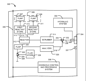
[0017] FIG. 3 depicts a block diagram of an example apparatus 300 that
may be
used to implement the example formation tester 214 of FIG. 2. In the
illustrated
example of FIG. 3, lines shown connecting blocks represent fluid and/or
electrical
connections that may include one or more flowlines (e.g., hydraulic flowlines
or
formation fluid flowlines) or one or more wires or conductive paths. As shown
in
FIG. 3, the example apparatus 300 includes a hydraulic system 302 that may be
fluidly coupled to the sampling probe 304 to extend the sampling probe 304
into
- 8 -
WO 2009/051936 CA 02702495 2010-04-09
PCT/US2008/077219
engagement with the formation F (FIG. 2) to enable injecting reactants and/or
a
product of a chemical reaction into the formation F (FIG. 2) and/or drawing of
a fluid
sample from the formation F (FIG. 2).
[0018] To inject chemical reactants and/or the product of a chemical
reaction into
the formation F (FIG. 2) through a sample flowline 306, the example apparatus
300 is
provided with a first pump 307 and a second pump 308 that form an injector
309. In
particular, the first pump 307 and/or the second pump 308 may be implemented
with
piston pumps used to move the one or more reactants from a first reactant
store 310
and/or a second reactant store 311 through flowlines 313 and 315, a reactor
312, and a
scrubber 314. Additionally, to draw formation fluid (e.g., from the formation
F)
through the sample flowline 306 and a sample flowline 318, the example
apparatus
300 is provided with a third pump 320 (e.g. a reciprocating pump). In
particular, the
third pump 320 draws or pumps formation fluid through the flowlines 306 and
318, a
fluid analyzer 325 and a valve 322, which has a first selectable outlet 324
that is
fluidly coupled to a fluid store 326 and a second selectable outlet 328 that
expels fluid
out of the formation tester 214 (FIG. 2) into, for example, the wellbore 202
of FIG. 2.
Although in this example the injector 309 is positioned upstream relative to
the first
and second reactant stores 310 and 311, in other example implementations, the
injector 309 may be in any other suitable position. Additionally, in other
example
implementations, the injector 309 may include an additional pump(s) (not
shown) that
may be adjacent the first and second pumps 307 and 308 or positioned in any
other
suitable location such as, for example, between the reactor 312 and the
scrubber 314
or between the scrubber 314 and the sampling probe 304.
[0019] The first reactant store 310 and/or the second reactant store
311 may be
provided with a plurality of chambers (not shown), which are to hold
reactant(s) that
- 9 -
WO 2009/051936 CA 02702495 2010-04-09
PCT/US2008/077219
are to be used in a chemical reaction such as, an exothermic reaction (i.e., a
chemical
reaction that releases heat). In other examples, the plurality of chambers are
to hold
reactants that are mixed (e.g., to form a mixture) prior to the wireline tool
200 (FIG.
2) being lowered into the wellbore 202 (FIG. 2). In this example, to initiate
a
chemical reaction, the mixture is exposed to a catalyst such as one of the
catalysts
described below. The reactants may be any suitable reactants including, for
example,
hydrogen peroxide, water, methanol, tertiary butyl carboxylic acid, tertiary
butyl
peroxide, ethanol, carbohydrates such as sugar, carbonated substances and/or
any
other water soluble compound that comprises at least carbon and hydrogen. In
some
examples, at least one of the reactants is an oxidizing agent such as, for
example,
hydrogen peroxide, tertiary butyl peroxide or tertiary butyl carboxylic acid.
In other
examples, at least one of the reactants may provide a fuel source such as, for
example,
a tertiary butyl carboxylic acid, tertiary butyl peroxide, methanol, ethanol,
sugar, a
carbonated substance or any other water soluble compound that comprises at
least
carbon and hydrogen.
[0020] Each of the chambers of the first reactant store 310 and/or the
second
reactant store 311 are to be filled with their respective reactant prior to
the wireline
tool 200 (FIG. 2) being lowered into the wellbore 202 (FIG. 2). However, the
chambers of the first reactant store 310 and/or the second reactant store 311
may be
filled and/or refilled using any other suitable method. In some examples, at
least part
of each of the reactants in each of the different chambers is used in a first
chemical
reaction. Alternatively, in some examples, at least a part of some of the
reactants are
used in the first chemical reaction and at least a part of different reactants
are used in
a second chemical reaction. Any suitable number of chambers (e.g., 1, 2, 3, 4,
5, etc.)
may be used to hold the same or different reactants.
- 10 -
WO 2009/051936 CA 02702495 2010-04-09
PCT/US2008/077219
[0021] The reactor 312 receives from the first reactant store 310 and/or
the
second reactant store 311 the one or more reactants used in the chemical
reaction.
The reactor 312 may combine (e.g., mix) two or more reactants to initiate the
chemical reaction. Alternatively, the reactor 312 may initiate a chemical
reaction in
which a single reactant decomposes. The reactor 312 may be provided with any
suitable catalyst such as, for example, a platinum metal dispersed on a
substrate of
aluminum oxide, manganese dioxide, titanium oxide or silica, that changes the
rate at
which the chemical reaction occurs. The catalyst may be in any suitable
arrangement
such as, for example, a grill arrangement, a lattice arrangement, a packed bed
arrangement or a filter pack arrangement to promote the exposure of the
reactant(s) to
the catalyst and/or accelerate the rate at which the chemical reaction occurs.
In some
examples, the product of the exothermic chemical reaction is only heat and a
gaseous
diluent (e.g. gaseous solvent). In other examples, the product of the
exothermic
chemical reaction includes at least heat and a gaseous diluent (e.g., gaseous
solvent).
The gaseous diluent may be dissolvable and/or miscible in a formation fluid
and the
gaseous diluent may be soluble within the formation fluid to cause a change in
a
viscosity of the formation fluid. Specifically, the gaseous diluent may be a
solvent
that at least partially dilutes the formation fluid by admixture.
Additionally, the
gaseous diluent may be able to migrate and/or diffuse within the formation
fluid
relatively quickly. Further, in some examples, exposing the formation fluid to
the
product of the chemical reaction does not substantially alter the formation
fluid and/or
change a chemical composition of the formation fluid.
[0022] Exposing a formation fluid to the product of the chemical reaction
may
decrease the viscosity of the formation fluid. For example, exposing the
formation
fluid to heat decreases the viscosity of the formation fluid, as shown, for
example, in
- 11 -
WO 2009/051936 CA 02702495 2010-04-09
PCT/US2008/077219
FIG. 1. Additionally, mixing a gaseous diluent with a formation fluid also
decreases
the viscosity of the formation fluid. However, if both heat and a gaseous
diluent are
substantially simultaneously exposed to a formation fluid, the reduction in
viscosity of
the formation fluid is surprisingly about 1.5 times greater than if only heat
or a
gaseous diluent alone were exposed to the formation fluid. As illustrated in
Equations
3 through 12 below, the gaseous diluent may be, for example, carbon monoxide
(CO),
carbon dioxide (CO2), oxygen (02), and/or hydrogen (H2). However, in other
examples, any other suitable element and/or component providing a chemical
reaction
that produces a product (e.g., heat and a gaseous dilutent) that is preferably
dissolvable and/or miscible in a formation fluid and which is associated with
increasing the mobility and/or decreasing the viscosity of a formation fluid
may be
used. As discussed in more detail below, at least part of the product of the
chemical
reaction is to be injected and/or exposed to the fluid in the subsurface
formation and
at least some of the components and/or elements (e.g., hydrogen (i.e., H2),
carbon
dioxide (i.e., CO2), and/or nitrogen (i.e., N2)) may at least partially
dissolve within the
formation fluid.
[0023] As illustrated in Equations 3 through 12 below, another product of
the
reaction also includes steam or water. While gaseous solvents are dissolvable
within
a formation fluid, water (H20) or steam and/or hot acid typically are not
readily
dissolvable within formation fluid. Water or steam may form foam and/or an
emulsion in the formation fluid, which, depending on the water concentration
within
the formation fluid, may also reduce the viscosity of the formation fluid.
However,
steam may alter some characteristics of the formation fluid and, thus, steam
may not
be appropriate to obtain samples of formation fluid because it may prevent the
- 12 -
CA 02702495 2010-04-09
WO 2009/051936
PCT/US2008/077219
analysis of the chemical composition and/or the physical properties of the
formation
fluid.
[0024] In some example subterranean formations such as heavy oil or
bitumen
formations, carbon dioxide and hydrogen are not typically present in formation
fluids
(e.g., not a pristine component of formation fluid) and, therefore, if either
hydrogen
and/or carbon dioxide are present in a formation fluid sample after hydrogen
and/or
carbon dioxide have been injected into the formation via the injector 309, the
fluid
analyzer 325 and/or any other testing device(s) will recognize that these
components
or elements were not previously present in the formation fluid. The testing
device(s)
may be positioned within the wireline tool 200 (FIG. 2) and/or may be
positioned up-
hole (e.g., in a laboratory, etc.).
[0025] Furthermore, though the examples described below describe chemical
reactions using certain elements and/or components, any chemical reaction
using any
suitable element and/or components may be used to produce at least a gaseous
diluent
and heat.
[0026] Equation 3
H202(1) + H20(1) + CH3OH(1) pt/A1203, T,800K >
[0027]
CO2(g) + 2H2(g) + 2H20(g) , ArHin = ¨653 kJ = moll
[0028] Equation 4
H202(1) + H20(1) + CH3OH(1) Pt/A1203, T,800K >
[0029] 1 1 1
¨ 0, (g) + ¨CO(g) + ¨ CO2(g) + 2H2(g) + 2H20(g) , ArHm = ¨511 kJ = mo1-1
4 - 2 2
- 13 -
WO 2009/051936 CA 02702495 2010-04-09
PCT/US2008/077219
[0030] The chemical reactions represented in Equations 3 and 4 produce
gaseous
products and relatively large standard molar enthalpies of reaction (e.g.,
heat content)
which are represented by H . The chemical reaction illustrated in
Equation 3,
provides a total energy of about 48 MJ (i.e., mega joules) with a volume of
about 1.5
dm3 (i.e., cubic decimeter) comprising 50% water (i.e., H20) and 50% hydrogen
peroxide (i.e., H202) and 0.8 dm3 methanol (i.e., CH3OH). In some examples,
the
components and/or elements represented in Equations 2 and 3 are exposed to a
catalyst such as, for example, a platinum material supported on aluminum oxide
(i.e.,
A1203) or any other suitable catalyst that may initiate or increase the rate
at which the
chemical reaction occurs. The reactor 312 may be provided with the catalyst.
In
other examples, the catalyst is positioned in any other suitable position such
as, for
example, within the sampling probe 304.
[0031] Any other suitable chemical compound or element may be substituted
for
any or all of the components or elements illustrated in Equations 3 and 4 such
as, for
example, methanol (i.e., CH3OH) may be substituted at least in part by ethanol
(e.g.,
CH3CH2OH), and/or a carbohydrate such as sugar, etc.
[0032] The standard molar enthalpies of Equations 3 and 4 were obtained
from
the enthalpy of liquid to gas transition, which is represented by for
water and
illustrated in Equation 5 below.
[0033] Equation 5
[0034] H 0(1) =FT 0(0) A H'' - 40.65J .inor m ¨
- 14 -
CA 02702495 2010-04-09
WO 2009/051936
PCT/US2008/077219
[0035] The standard molar enthalpies and the enthalpy of liquid to gas
transition
were combined with the standard molar enthalpy of formation, which is
represented
by and illustrated in Equations 6, 7, 8, 9, and 10 below.
[0036] Equation 6
H (g) + H10 J1) (I) . A,Hc = ¨188.8 D mor
_
[0037] -
[0038] Equation 7
H2 (g) (g) 'FLOW, = ¨287.6 kJ ,inor
[0039]
[0040] Equation 8
Qs) 211 (g) + - 0, (g) = CH i0H(1) = 240.2 Id
-
[0041]
[0042] Equation 9
C.(S) ¨ 0, (a) = CO( g), = ¨Ii L2 kir morl
[0043]
[0044] Equation 10
C(s) g) = CO , (g) ¨395.9 D moI-1
[0045]
[0046] An alternative chemical reaction that may have a lower enthalpy of
reaction is illustrated below in Equation 11. Equation 11 illustrates an
example
chemical reaction in which hydrogen peroxide (H202) is decomposed to create
water
(e.g., steam) and oxygen (02). In some examples, the hydrogen peroxide is
exposed
to a catalyst such as, for example, a silver (i.e., Ag) screen and/or a
platinum (i.e., Pt)
screen) to initiate the decomposition (e.g., the chemical reaction).
- 15 -
WO 2009/051936 CA 02702495 2010-04-09
PCT/US2008/077219
[0047] Equation 11
00481 H (1) = +¨ O., (a), A = ¨98,2 kJ mot'
[0049] The product(s) of the chemical reaction proceed through the
scrubber 314
from the reactor 312. The scrubber 314 removes unwanted components from the
product of the chemical reaction. As illustrated above, the chemical reactions
represented by Equations 3 and 4 produce carbon dioxide (CO2). Carbon dioxide
may
be dissolvable within a formation fluid without causing precipitation of
asphaltenes.
However, precipitation of asphaltenes may occur after a certain amount of
carbon
dioxide is dissolved within the formation fluid. Precipitation of asphaltenes
is
associated with solid particles forming within the formation fluid that may
clog the
formation, slow the rate at which a fluid sample is obtained, decrease the
rate at which
the mobility of the formation fluid increases, and/or alters (e.g., chemically
alters) the
formation fluid sampled following an exposure to the products of the chemical
reaction. Having the product of chemical reaction pass through the scrubber
314 may
substantially eliminate the presence of carbon dioxide and/or any other
unwanted
elements or components from the product of the chemical reaction to prevent
its
introduction into the formation fluid and, thus, substantially prevent
precipitation of
asphaltenes. In other examples, the example apparatus 300 may not be provided
with
the scrubber 314.
[0050] The injector 309 injects (e.g., moves) the product of the chemical
reaction
from the scrubber 314 into the formation F (FIG. 2). The injector 309 may be
provided with any other suitable device to assist in injecting the product of
the
chemical reaction into the formation F (FIG. 2). The reactant stores 310 and
311, the
reactor 312 and the injector 309 are fluidly coupled to the sampling probe 304
via a
- 16 -
WO 2009/051936 CA 02702495 2010-04-09
PCT/US2008/077219
valve 332, which has a first selectable outlet 334 that is fluidly coupled to
the
scrubber 314 and a second selectable outlet 336 that is fluidly coupled to the
fluid
analyzer 325. Although the injector 309 and the first and second reactant
stores 310
and 311 are shown as being separate from the reactor 312 and the scrubber 314,
in
some examples, the reactor 312 and/or the scrubber 314 may be in or relatively
closer
(e.g., in engagement with) the injector 309 as discussed in more detail below
in
connection with FIG. 5.
[0051] In another example implementation (not shown), the example
apparatus
300 may be provided with a plurality of sampling probes (not shown) as
described in
U.S. Patent Application Publication No. 2008/0066536 and U.S. Patent
Application
Publication No. 2008/0066904, both of which are assigned to the assignee of
the
present patent and incorporated herein by reference in their entireties. In
this
example, at least one of the sampling probes may inject and/or expose the
product of a
chemical reaction to the formation F (FIG. 2), and at least one other sampling
probe
may obtain a sample of the formation fluid from the formation F (FIG. 2).
[0052] To measure properties and/or characteristics of the formation
fluid, the
example apparatus 300 is provided with a formation evaluation sensor 337. The
formation evaluation sensor 337 may monitor a viscosity of the fluid in the
subsurface
formation before, during and/or after the injector 309 has injected the
product of the
chemical reaction into the formation F. The formation evaluation sensor 337
may
identify a change in the viscosity of the formation fluid such as, for
example, the
formation evaluation sensor 337 may identify when the formation fluid has
become
sufficiently mobile to enable sampling of the formation fluid. For example,
the
formation evaluation sensor 337 may be provided with a NMR tool (not shown) to
make NMR measurements and to at least partially determine characteristics of
the
- 17 -
WO 2009/051936 CA 02702495 2010-04-09
PCT/US2008/077219
formation fluid associated with the viscosity of the formation fluid within
the
formation before, during and/or after the product of the chemical reaction is
exposed
to the formation F.
[0053] Once the mobility of the formation fluid has increased by
decreasing the
viscosity of the formation fluid, a sufficient amount of the product has been
exposed
to the formation F, and/or a specified time as lapsed, the injector 309 stops
injecting
the product of the chemical reaction into the formation F and the third pump
320
draws a sample of the formation fluid (e.g., from the formation F) through the
sample
flowlines 306 and 318, to the fluid analyzer 325. The formation fluid may be
any
type of formation fluid such as, for example, a wellbore fluid, a fluid
extracted from
subsurface formation, a heavy oil, a bitumen, a gas condensate, a hydrocarbon
fluid, a
typical crude oil, methane hydrate or a drilling fluid. In some examples, the
formation fluid may be an oil-based drilling fluid or a filtrate of an oil-
based drilling
fluid mixed with a formation hydrocarbon. The example apparatus 300 of FIG. 3
may
be configured to use the flowline 318 to enable fluid samples to be analyzed
by the
fluid analyzer 325 to determine a characteristic of the formation fluid and/or
to enable
fluid samples to be stored in the fluid store 326 or expelled into the
wellbore 202
(FIG. 2). The fluid analyzer 325 may be used to determine a characteristic of
the fluid
sample such as, for example, a chemical composition, a density, a gas-oil
ratio, a
viscosity, a thermal conductivity, and/or a heat capacity. Although not shown,
the
fluid analyzer 325 may be provided with one or more suitable sensor(s)
including, for
example, a nuclear magnetic resonance (NMR) sensor, a density senor, a
capacitance
sensor, a volume sensor, a spectrometer, a resistivity measurement device
(e.g., an
ohmmeter), etc. to measure fluid characteristics.
- 18 -
WO 2009/051936 CA 02702495 2010-04-09
PCT/US2008/077219
[0054] To control the hydraulic system 302, the reactor 312, the scrubber
314, the
injector 309, the third pump 320, the valves 322 and 332, the formation
evaluation
sensor 337 and the fluid analyzer 325, the example apparatus 300 is provided
with a
downhole control and processing system 338. Although not shown, the downhole
control and processing system 338 may include a processor, one or more
memories,
and a communication interface (e.g., a modem). The communication interface of
the
downhole control and processing system 338 may be communicatively coupled to a
surface system (e.g., the electronics and processing system 206 of FIG. 2) via
wires or
lines 340 (FIG. 3), and/or the cable 204 (FIG. 2) to communicate reactant
data,
chemical reaction data, analysis data, and/or receive control data. The wires
or lines
340 may include a databus (e.g., carrying digital information and/or analog
information), electrical power lines, etc. and may be implemented using a
single
conductor or multiple conductors.
[0055] In operation, the downhole control and processing system 338 may be
used to control the hydraulic system 302 to cause the sampling probe 304 to
engage
the formation F (FIG. 2). The downhole control and processing system 338 may
control the injector 309 to move the reactants and/or the product of the
chemical
reaction through the flowlines 306, 313 and 315, the reactor 312, and the
scrubber
314. The downhole control and processing system 338 may control when the
formation evaluation sensor 337 monitors (e.g., measures, tests) the viscosity
of the
formation fluid such as, for example, before, during, or after the injector
309 has
injected the product of the chemical reaction into the formation F (FIG. 2).
Additionally, the formation evaluation sensor 337 communicates to the downhole
control and processing system 338 when the formation evaluation sensor 337
identifies that the viscosity and/or the formation fluid has become
sufficiently mobile
- 19 -
WO 2009/051936 CA 02702495 2010-04-09
PCT/US2008/077219
to enable sampling of the formation fluid. Additionally, the downhole control
and
processing system 338 may also control the third pump 320 to draw formation
fluid
through the flowlines 306 and 318 and the fluid analyzer 325.
100561 Now turning to FIG. 4, a detailed block diagram of an example
apparatus
400 that includes an example first reactant store or chamber 402 that retains
a first
reactant, a second reactant store or chamber 404 that retains the second
reactant,
which may be substantially the same or different from the first reactant.
Additionally,
the example apparatus is provide with a first pressure source 406 and a second
pressure source 408, that may be the same or different from the first pressure
source
406. The first and second pressure sources 406 and 408, which may be
implemented
as pumps, form an injector 410, which may be used to implement the injector
309 of
FIG. 3. The example apparatus 400 also includes an example reactor 412, which
may
be used to implement the reactor 312 of FIG. 3. The first reactant store or
chamber
402 and the second reactant store or chamber 404 may be fluidly coupled to the
reactor 412 via flowlines 414 and 416, which are represented in FIG. 3 by the
flowlines 306, 313 and 315. A metering valve 418 (e.g. a needle valve)
positioned
between the first reactant store or chamber 402 and the reactor 412 has a
first
selectable outlet 420 that is fluidly coupled to the reactor 412. A metering
valve 422
positioned between the second reactant store or chamber 404 and the reactor
412 has a
first selectable outlet 424 that is fluidly coupled to the reactor 412. A
sensor 426 is
positioned adjacent the reactor 412 and may monitor a characteristic of the
product of
the chemical reaction such as the temperature. If the temperature of the
product of the
chemical reaction is too low or too high as compared to a desired temperature,
the
flow rate of the reactant(s) from the first and/or second reactant stores or
chambers
- 20 -
WO 2009/051936 CA 02702495 2010-04-09
PCT/US2008/077219
402 and 404 may change to substantially achieve the desired temperature of the
product of the chemical reaction.
[0057] The first and second pressure sources 406 and 408 may be used to
provide
a sufficient pressure level to inject the reactants or a product of a chemical
reaction
between the reactants into a formation. The first pressure source 406 and/or
the
second pressure source 408 pumps or moves at least a part of the different
reactants
through the flowlines 414 and 416 to the reactor 412. In some examples, the
quantity
and/or rate at which the first reactant is moved from the first reactant store
or chamber
402 to the reactor 412 is substantially the same as the quantity and/or rate
at which the
second reactant is moved from the second reactant store or chamber 404 to the
reactor
412. In other examples, the amount and/or rate (e.g., speed) at which the
first reactant
is moved from the first reactant store or chamber 402 to the reactor 412 is
different
from the quantity and/or rate at which the second reactant is moved from the
second
reactant store or chamber 404 to the reactor 412. Specifically, the quantity
and/or rate
at which the first and second reactants move from the first and second
reactant stores
or chambers 402 and 404 through the flowlines 414 and 416 to the reactor 412
is
associated with a stoichiometric ratio. For example, 2 liters (L) of hydrogen
peroxide
(H202) may be moved from the first reactant store or chamber 402 to the
reactor 412
and 1 liter (L) of methanol (CH3OH) may be moved from the second reactant
store or
chamber 404 to the reactor 412. In other examples, only one reactant is used
in a
chemical reaction such as, for example, the decomposition of hydrogen
peroxide. In
some examples, some or all of the reactants may be in a substantially liquid
state. In
other examples, some or all of the reactants may be in a substantially gaseous
state or
any other suitable state.
- 21 -
WO 2009/051936 CA 02702495 2010-04-09
PCT/US2008/077219
[0058] As described above, the reactor 412 receives the reactant(s) from
the first
reactant store or chamber 402 and/or the second reactant store or chamber 404
and
may be used to mix the reactants together and expose the reactants to a
catalyst that
may be positioned within the reactor 412. In other examples, the first
reactant and the
second reactant are mixed in the reactor 412 and then exposed to a catalyst
that is in
or relatively close to the sampling probe 304 (FIG. 3) and, thus, the first
reactant and
the second reactant are exposed to the catalyst substantially adjacent to the
formation.
In still other examples, the catalyst is positioned in a heat pipe 514 (FIG.
5) or
injection probe. For example, if the heat pipe 514 (FIG. 5) is provided with
the
catalyst and positioned, for example, at least partially within the formation
F (FIG. 2)
(e.g., up to 1m), the first and second reactants may be exposed to the
catalyst at least
partially within the formation F.
[0059] The positioning of the flowlines 414 and 416 relative to the
reactor 412
may be at least in part to substantially delay the first reactant from the
first reactant
store or chamber 402 from reacting with the second reactant from the second
reactant
store or chamber 404 and, thus, may substantially delay the initiation of the
chemical
reaction until the first and second reactants are adjacent to or within the
formation F
(FIG. 2) or closer to the formation F (FIG. 2). Delaying the chemical reaction
may
allow for substantially more of the product(s) of the chemical reaction (e.g.,
heat
and/or a gaseous diluent) to be injected and/or exposed to the formation F
and, thus,
may increase the rate at which a characteristic (e.g., mobility) of the
formation fluid
changes and the rate at which a formation sample may be obtained.
Additionally,
delaying the chemical reaction until the reactants and/or the product of the
chemical
reaction is about to be exposed and/or injected into the formation F (FIG. 2)
minimizes the exposure that components of the example apparatus 300 and 400 of
- 22 -
WO 2009/051936 CA 02702495 2010-04-09
PCT/US2008/077219
FIGS. 3 and 4 or an example apparatus 500 of FIG. 5 have to the product of the
chemical reaction and, thus, may extend the useful life and/or reduce wear and
tear on
the example apparatus 300, 400, and 500.
[0060] Now turning to FIG. 5, a detailed block diagram of the example
apparatus
500 (e.g., an injector unit 500) that may be used to implement the sampling
probe
304, the reactor 312 and the injector 309 of FIG. 3. The example apparatus 500
includes an example first flow channel 502 and an example second flow channel
504.
The second flow channel 504 is fluidly coupled to the first and second
reactant stores
310 and 311 and the first flow channel 502 is fluidly coupled to a fluid store
506. The
fluid store 506 may store any suitable fluid and/or heat transfer fluid such
as, for
example, water or previously extracted formation fluid that may be used to
convey at
least part of the heat from the chemical reaction to the formation F. The heat
transfer
fluid may be moved and/or pumped to the first flow channel 502 via a pump 507.
The
first reactant and/or the second reactant flows from the reactant stores 310
and 311
through the second flow channel 504 toward an opening 510 defined by the
second
flow channel 504 at a first flow rate and the fluid from the fluid store 506
flows from
the fluid store 506 through the first flow channel 502 toward an opening 512
defined
by the first flow channel 502 at a second flow rate. Alternatively, the
apparatus 500
may not be provided with the fluid store 506 and the first reactant store 310
may be
fluidly coupled to the first flow channel 502 and the second reactant store
311 may be
fluidly coupled to the second flow channel 504. The rate at which the first
reactant
and the second reactant flow through the second flow channel 504 and/or the
first and
second flow channels 502 and 504 may be associated with a stoichiometric
ratio.
[0061] Once the first and second reactants enter the second flow channel
504, the
second reactant at least partially mixes with the first reactant and initiates
the
- 23 -
WO 2009/051936 CA 02702495 2010-04-09
PCT/US2008/077219
chemical reaction. The chemical reaction produces at least heat and a gaseous
diluent. As the first and second reactants flow through the second flow
channel 504, a
heat transfer fluid flows through the first flow channel 502 and at least part
of the heat
from chemical reaction radiates and/or conducts through the second flow
channel 504
to the heat transfer fluid and, thus, the temperature of the heat transfer
fluid increases.
Along with the first and second reactants, the heat transfer fluid exits the
opening 512
into the formation F (FIG. 2). Alternatively, once the second reactant exits
the
opening 510, the second reactant at least partially mixes with the first
reactant before
both the first and second reactants exit the opening 512 defined by the first
flow
channel 502 into the formation F (FIG. 2). In this example, mixing the first
reactant
with the second reactant initiates a chemical reaction.
[0062] The first flow channel 502 is substantially concentric with the
second flow
channel 504. The position of the first flow channel 502 relative to the second
flow
channel 504 may substantially control when the first reactant contacts the
second
reactant and, thus, as discussed above, the initiation of the chemical
reaction may be
delayed until the first reactant and the second reactant are substantially
adjacent to or
within the formation F (FIG. 2).
[0063] The first flow channel 502 may be provided with the heat pipe 514
that
may be partially inserted into a perforation 515 of the formation and may be
used to
implement the sampling probe 304 of FIG 3. The perforation 515 may be formed
via
a tool (not shown) as described in U.S. Patent 5,692,565 and U.S. Patent
7,347,262
both of which are assigned to the assignee of the present patent and
incorporated
herein by reference in their entireties. In this example, the heat pipe 514 is
a
cylindrical sleeve that enables the product(s) of the chemical reaction to
flow through
the opening 512 and into the formation F (FIG. 2). Specifically, at least part
of the
- 24 -
WO 2009/051936 CA 02702495 2010-04-09
PCT/US2008/077219
gaseous diluent and heat from the exothermic chemical reaction flows through
the
opening 510 and into the formation F (FIG. 2). Additionally, at least part of
the heat
from the exothermic reaction radiates and/or is conducted through an exterior
surface
516 of the heat pipe 514 and into the formation F (FIG. 2). The heat pipe 514
may be
any suitable device and may be made of any suitable thermally conductive
material
that is able to withstand being in a downhole environment and exposed to the
product
of the chemical reaction.
[0064] The second flow channel 504 is provided with a catalyst 518 that at
least
partially contacts the first and second reactants as they flow through the
second flow
channel 504. The catalyst 518 may be in any suitable arrangement such as, for
example, a grill arrangement, a lattice arrangement, a packed bed arrangement
or a
filter pack arrangement. The catalyst 518 may be in any other suitable
position such
as, for example, a position within the first flow channel 502 and the position
of the
catalyst 518 relative to the first and/or second reactants may be associated
with
delaying and/or changing when the chemical reaction occurs. In other examples,
the
first flow channel 502 may be in any other suitable position relative to the
second
flow channel 504, such as, for example, the first flow channel 502 may be
substantially parallel to the second flow channel 504. A sensor 520 is at
least partially
positioned within the second flow channel 504 and may monitor a characteristic
of the
product of the chemical reaction such as the temperature. If the temperature
of the
product of the chemical reaction is too low or too high as compared to a
desired
temperature, the flow rate of the reactant(s) from the first and second
reactant stores
310 and 311 may change to substantially achieve the desired temperature.
[0065] FIG. 6 is a flow diagram of an example method 600 that may be used
to
change the mobility of a fluid in a subsurface formation. The example method
600 of
- 25 -
WO 2009/051936 CA 02702495 2010-04-09
PCT/US2008/077219
FIG. 6 may be used to implement the example formation tester 214 of FIG. 2,
the
example apparatus 300 of FIG. 3 and/or the examples apparatus 400 and 500 of
FIGS.
4 and 5. In some examples, the flow diagram can be representative of machine
(e.g.,
computer, processor, etc.) readable instructions and the example method of the
flow
diagram may be implemented entirely or in part by executing the machine
readable
instructions. Such machine readable instructions may be executed by the
electronics
and processing system 206 and/or the downhole control and processing system
338.
In particular, a processor or any other suitable device to execute machine
readable
instructions may retrieve such instructions from a memory device (e.g., a
random
access memory (RAM), a read only memory (ROM), etc.) and execute those
instructions. In some examples, one or more operations depicted in the flow
diagram
of FIG. 6 may be implemented manually.
[0066] While an example manner of implementing the example formation
tester
214 of FIG. 2, the example apparatus 300 of FIG. 3 and/or the example
apparatus 400
and 500 of FIGS. 4 and 5 has been illustrated in FIG. 6, one or more of the
elements,
methods and/or operations illustrated in FIG. 6 may be combined, divided, re-
arranged, omitted, eliminated and/or implemented in any other way. Any of the
operations of the example method described in FIG. 6 may be implemented by
hardware, software, firmware and/or any combination of hardware, software
and/or
firmware, including, for example, by one or more circuit(s), programmable
processor(s), application specific integrated circuit(s) (ASIC(s)),
programmable logic
device(s) (PLD(s)) and/or field programmable logic device(s) (FPLD(s)), etc.
Further still, the example method of FIG. 6 may include one or more elements,
processes and/or devices in addition to, or instead of, those illustrated in
FIGS. 6,
- 26 -
WO 2009/051936 CA 02702495 2010-04-09
PCT/US2008/077219
and/or may include more than one of any or all of the illustrated elements,
methods
and devices.
[0067] Initially, one or more reactants that are stored in the first
and/or second
reactant stores 310 and 311 (FIG. 3) are moved (block 602) via the pumps 307
and
308 (FIG. 3) toward, for example, the reactor 312 (FIG. 3). In the example
apparatus
400 of FIG. 4, the reactants flow from the first and second reactant stores or
chambers
402 and 404 (FIG. 4) through the flowlines 414 and 416 (FIG. 4) toward the
reactor
412 (FIG. 4). In the example apparatus 500 of FIG. 5, the reactants flow
through the
first flow channel 502 (FIG. 5) and/or the second flow channel 504 (FIG. 5).
As
discussed above, the first reactant and/or the second reactant may be exposed
to a
catalyst (block 604) before, during or after the first reactant has come into
contact
with the second reactant. A catalyst may substantially increase the rate at
which a
chemical reaction occurs and may not be substantially consumed by the chemical
reaction.
[0068] To initiate a chemical reaction, the first reactant is exposed to
the second
reactant and/or the catalyst (block 606). The injector 309 (FIG. 3) moves the
product(s) of the chemical reaction from the reactor 312 (FIG. 3) and/or the
scrubber
314 (FIG. 3) and injects and/or exposes the product(s) of the chemical
reaction to the
formation F (FIG. 2) (block 608). In some examples, the sampling probe 304
(FIG. 3)
and/or the injector unit 500 (FIG. 5) may be provided with the heat pipe 514
(FIG. 5)
or any other means to efficiently conduct heat produced by the chemical
reaction to
the formation F (FIG. 2) and to convey a gaseous diluent produced by the
chemical
reaction into the formation F (FIG. 2).
[0069] As discussed above, heating the formation F (FIG 2) and/or
formation
fluid to reduce the viscosity of a formation fluid is a thermal stimulation
technique,
- 27 -
WO 2009/051936 CA 02702495 2010-04-09
PCT/US2008/077219
and exposing and/or injecting a gaseous diluent into a formation fluid is a
non-thermal
stimulation technique. As illustrated by the equations above (i.e., Equations
3 through
12), the products of the example chemical reactions used by the example
methods and
apparatus described herein involves both heat and a gaseous diluent and,
therefore,
when the product of the chemical reaction is exposed and/or injected into the
formation F the product of the chemical reaction provides both heat to
increase the
temperature of the formation (i.e., a thermal stimulation) and a gaseous
diluent that is
to be dissolved in the formation fluid (e.g., a non-thermal stimulation) to
change the
viscosity of the formation fluid (block 610).
100701 The example method then determines if the formation mobility has
sufficiently changed (e.g., the viscosity has decreased sufficiently) to
enable sampling
of the formation fluid (block 612). As described above, the example apparatus
300
(FIG. 3) may be provided with the formation evaluation sensor 337 (FIG. 3) to
monitor changes in the formation fluid viscosity as the product of the
chemical
reaction is exposed to and/or injected into the formation F (FIG. 2). In this
manner,
the properties of the formation fluid may be evaluated during injection of the
product
of the chemical reaction into the formation F (FIG. 2) to, for example,
determine
when the mobility of the formation fluid has changed sufficiently to be
sampled by
the sampling probe 304 (FIG. 3) (block 612). In some implementations,
formation
fluid viscosity measurements may be used to control the amount of time and/or
the
rate at which the product of chemical reaction is exposed to the formation F
(FIG. 2).
If the formation mobility has sufficiently changed, the fluid is sampled
(block 614).
On the other hand, if it is determined that the formation mobility (e.g.,
formation fluid
viscosity) has not changed sufficiently, control returns to block 602 and
another
chemical reaction is initiated as discussed above.
- 28 -
WO 2009/051936 CA 02702495 2010-04-09
PCT/US2008/077219
[0071] Once a sample is obtained, the fluid analyzer 325 (FIG. 3)
determines or
identifies a characteristic of the fluid sample (block 616). In some examples,
the
characteristic is a partial chemical composition, a density, a gas-oil ratio,
a viscosity,
an estimate of fluid mobility, a thermal conductivity, a heat capacity, a
thermal
diffusivity and/or a self diffusivity. The fluid analyzer 325 (FIG. 3) may be
implemented using any suitable analyzer such as, for example, a spectrometer,
a
resistivity measurement device (e.g., ohmmeter), etc. Additionally, the
downhole
control and processing system 338 (FIG. 3) and/or the electronics and
processing
system 206 (FIG. 2) may be configured to store measurement data corresponding
to
the fluid sample.
[0072] The downhole control and processing system 338 then determines
whether
it should initiate another chemical reaction (block 618). For example, if the
example
apparatus 300 determines that another fluid sample is necessary and the
downhole
control and processing system 338 has not received an instruction or command
to stop
initiating another chemical reaction, the downhole control and processing
system 338
may determine that it should initiate another chemical reaction. Otherwise,
the
example process of FIG. 6 is ended.
[0073] Although certain example methods, apparatus and articles of
manufacture
have been described herein, the scope of coverage of this patent is not
limited thereto.
On the contrary, this patent covers all methods, apparatus and articles of
manufacture
fairly falling within the scope of the appended claims either literally or
under the
doctrine of equivalents.
- 29 -