Note: Descriptions are shown in the official language in which they were submitted.
CA 02702625 2010-04-14
WO 2009/058366 PCT/US2008/012377
BREATH DELIVERY SYSTEM AND METHOD
RELATED APPLICATIONS
[0001] This application claims priority to United States Provisional
Application No.
61/001,172 filed on October 31, 2007. The entire disclosure of the prior
application is
considered part of the accompanying application and is hereby incorporated
therein by
reference.
BACKGROUND
[0002] Current state of the art mouthpieces for drug delivery use liquids in
inhalant and
nebulizer mouthpieces in order to deliver therapeutic drugs to a user.
However, these
mouthpieces are only used for drug delivery (i.e., inhaling contents delivered
by the
mouthpiece) and therefore do not incorporate any type of sensing systems for
vapor analysis
(e.g., analyzing breath contents exhaled through the mouthpiece).
[0003] Some conventional mouthpieces used for vapor analysis (e.g., breath
analyte
analysis) use a particular breath collection method that requires multiple
components. For
example, a user exhales into the mouthpiece, a condenser removes breath
moisture, and an
attached container is used to trap a final breath sample. An analyte biosensor
is used for
subsequent analyte analysis. The analyte biosensor is either located within
the attached
container or in a separate piece of analysis equipment that obtains a breath
sample from the
container. The analyte biosensor chemically reacts with the one or more
analytes in the
breath sample. The presence of a reaction signifies the presence of the
specific analytes, and
the strength of the reaction can signify the amount of analyte in the breath
sample. The
amount of moisture removed from the condenser can be inconsistent and
variations due to
different mammalian moisture content in the breath can alter the speed and/or
strength of the
reaction on the analyte biosensor. As none of these mouthpieces incorporate
any type of
hydration system to create an environment with consistent moisture content for
each reaction,
results may be inaccurate.
CA 02702625 2010-04-14
WO 2009/058366 PCT/US2008/012377
2
SUMMARY
[0004] Some embodiments of the invention provide a mouthpiece for use with an
electronic analyzer for breath analyte detection in an individual. The
mouthpiece includes a
biosensor that detects breath analytes and a hydration system. The biosensor
includes a
chemically active area where a chemical reaction takes place. The hydration
system delivers
a liquid to the chemically active area of the biosensor to at least one of
enhance, enable, and
facilitate the chemical reaction. The mouthpiece further includes an
additional sensor
capable of detecting additional parameters and hardware to transmit breath
analyte data and
the additional parameters.
[0005] Some embodiments of the invention provide a mouthpiece that includes a
biosensor. The biosensor includes a chemically active area where a chemical
reaction takes
place and is capable of detecting analytes in at least one of breath, saliva,
urine, eye vapor,
milk and blood. The mouthpiece also includes a hydration system providing
liquid to the
chemically active area of the biosensor to at least one of enhance, enable,
and facilitate the
chemical reaction.
[0006] Other aspects of the invention will become apparent by consideration of
the
detailed description and accompanying drawings.
BRIEF DESCRIPTION OF THE DRAWINGS
[0007] FIG. I is a schematic illustration of a mouthpiece with an integrated
biosensor
according to one embodiment of the invention.
[0008] FIG. 2 is a schematic illustration of a mouthpiece with an integrated
biosensor
with an integrated manual liquid delivery system according to one embodiment
of the
invention.
[0009] FIG. 3 is a schematic illustration of a mouthpiece with an integrated
biosensor
with liquid delivery to the biosensor provided by a fluid filled sack
according to one
embodiment of the invention.
[0010] FIGS. 4A and 4B are a schematic illustration and a flow chart of a
semiautomatic
plunger method of hydration according to one embodiment of the invention.
CA 02702625 2010-04-14
WO 2009/058366 PCT/US2008/012377
3
[0011] FIG. 5 is a schematic illustration of a mouthpiece with an integrated
biosensor
with a pump line used to perform liquid delivery to the biosensor according to
one
embodiment of the invention.
DETAILED DESCRIPTION
[0012] Before any embodiments of the invention are explained in detail, it is
to be
understood that the invention is not limited in its application to the details
of construction and
the arrangement of components set forth in the following description or
illustrated in the
following drawings. The invention is capable of other embodiments and of being
practiced
or of being carried out in various ways. Also, it is to be understood that the
phraseology and
terminology used herein is for the purpose of description and should not be
regarded as
limiting. The use of "including," "comprising," or "having" and variations
thereof herein is
meant to encompass the items listed thereafter and equivalents thereof as well
as additional
items. Unless specified or limited otherwise, the terms "mounted,"
"connected,"
"supported," and "coupled" and variations thereof are used broadly and
encompass both
direct and indirect mountings, connections, supports, and couplings. Further,
"connected"
and "coupled" are not restricted to physical or mechanical connections or
couplings.
[0013] The following discussion is presented to enable a person skilled in the
art to make
and use embodiments of the invention. Various modifications to the illustrated
embodiments
will be readily apparent to those skilled in the art, and the generic
principles herein can be
applied to other embodiments and applications without departing from
embodiments of the
invention. Thus, embodiments of the invention are not intended to be limited
to
embodiments shown, but are to be accorded the widest scope consistent with the
principles
and features disclosed herein. The following detailed description is to be
read with reference
to the figures, in which like elements in different figures have like
reference numerals. The
figures, which are not necessarily to scale, depict selected embodiments and
are not intended
to limit the scope of embodiments of the invention. Skilled artisans will
recognize the
examples provided herein have many useful alternatives and fall within the
scope of
embodiments of the invention.
[0014] FIG. 1 illustrates a mouthpiece 10 connected to an electronic analyzer
100,
according to some embodiments of the invention. The mouthpiece 10 can be made
of a
polymer material, such as polyethylene. The mouthpiece 10 can include an
integrated
CA 02702625 2010-04-14
WO 2009/058366 PCT/US2008/012377
4
biosensor 11, an inlet 12, an outlet 13, and electrical connectors 14. The
electrical connectors
14 can connect to an electrical connector receptacle 101 on the electronic
analyzer 100. The
mouthpiece 10 including the integrated biosensor 11 can be used for the direct
detection of
breath analytes. The biosensor 11 can include a chemically-active area, such
as an area
including an enzyme, to permit a chemical reaction when in contact with an
analyte. For
example, the biosensor 11 can be an enzymatic electrochemical breath acetone
sensor. As
shown in FIG. 1, the biosensor 11 can be integrated directly into the
mouthpiece 10, therefore
removing the need for a breath container. The mouthpiece 10 and/or biosensor
11 can be
reusable or disposable. The biosensor 11 can be in the form of a sensor strip.
During use, an
individual can exhale through the inlet 12, causing breath gasses to flow
directly over the
biosensor 11 and out through the outlet 12. A reaction on the biosensor 11 in
response to the
breath gasses can take place directly within the mouthpiece 10. In addition,
the electrical
connectors 14 can transmit analyte data to the electronic analyzer 100 in
response to the
reaction taking place.
[0015] The electronic analyzer 100 can include a display 103 and user
interface 104. The
electronic analyzer 100 can be a PDA, cell phone, computer, iPod , or any
device capable of
receiving, storing, and/or transmitting data from the biosensor 11.
Alternatively, the
electronic analyzer 100 can be a sensing device specific to the analyte or
analytes being
detected, such as a breath analyte sensing device for acetone. In various
embodiments, the
mouthpiece 10 can be mechanically or electrically embedded, or mechanically or
electrically
integrated into the electronic analyzer 100. In other embodiments, the
mouthpiece 10 can
include hardware such as a transmitter to transmit data wirelessly to an
electronic analyzer
100.
[0016] In some embodiments, the biosensor 11 can require a hydration material
in order
to enable, facilitate, and/or enhance the enzymatic reaction. Variations due
to different
mammalian moisture content in the breath can alter the speed and/or strength
of the reaction.
To help provide accurate results with improved precision, the mouthpiece 10
can include an
integrated hydration system. The hydration system can provide a consistent
amount of
hydration material to the biosensor I 1 prior to each reaction. The hydration
material can be
water, an acid, a base, a neutral buffer, a hydrogel, a salt solution, or a
liquid containing
polymers. The hydration material can depend on the type of biosensor 11. In
some
CA 02702625 2010-04-14
WO 2009/058366 PCT/US2008/012377
embodiments, the viscosity of the hydration material can range from about 0.1
centipoise (cP)
to about 200,000 centipoise.
[0017] The hydration system can be used to hydrate a dried enzyme on the
biosensor 11.
The analyte detected by the biosensor 11 can be some kind of volatile, such as
acetone in
mammalian breath for fat-burn monitoring or volatile organic compounds (VOCs)
for disease
or cancer detection. Other volatile-carrying mediums, such as vapor or a gas,
can be
analyzed using the biosensor 11 and the hydration system. Some examples
include volatile
analyte analysis in animal milk, eye vapor, urine, or mucus. For example, the
mouthpiece 10
can act as a chamber containing biosensor 11 with the incorporated hydration
system over
which vapors from the eye, animal milk, blood, or urine is drawn, for example
by a pump.
[00181, In some embodiments, the actuation of the hydration process can be
fully manual.
For example, FIG. 2 illustrates a reservoir-based hydration system. As shown
in FIG. 2, a
mouthpiece 20 can include a wetting port 21. The wetting port 21 can be a
small hole in the
mouthpiece 20 above the biosensor 11. The wetting port 21 can be of a size
suitable to allow
clearance of a syringe or pipette tip 22. The syringe or pipette 22 can be
used to manually
wet the biosensor 11 prior to analysis. In some embodiments, the volume range
of hydration
material can be about 0.05 micro-liters to about 100 micro-liters.
[0019] FIG. 3 illustrates a hydration process according to another embodiment
of the
invention. FIG. 3 illustrates a mouthpiece 30 including a fluid-filled sack
31. The sack 31
(also known as a blister pack) can be housed within the mouthpiece 30 near the
biosensor 11
or integrated onto the sensor strip of the biosensor 11. In some embodiments,
a pin 32,
syringe, or roller can be used to manually pierce or puncture the sack 31 to
hydrate the active
area of the biosensor 11. In other embodiments, a pushbutton (not shown) on
the mouthpiece
can include a piercing pin to pierce the sack 31 when the pushbutton is
depressed. In other
embodiments, the pin 32 or roller can be housed within the mouthpiece 30 and
can be
depressed to pierce the sack 31 remotely by the electronic analyzer 100 or
another electronic
device to which the mouthpiece 30 is electrically connected.
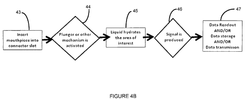
[0020] FIGS. 4A-4B illustrate a semi-automatic hydration process according to
another
embodiment of the invention. FIG. 4A illustrates a mouthpiece 40 including a
hydration tube
41 and a plunger 42. FIG. 4B illustrates example method steps for performing
the semi-
automatic hydration process with the plunger 42. The mouthpiece 40 can be
coupled to the
CA 02702625 2010-04-14
WO 2009/058366 PCT/US2008/012377
6
electronic analyzer 100 by the electrical connectors 14 (task 43). The plunger
42 can be
coupled to the mouthpiece 40 such that coupling the mouthpiece 40 to the
electronic analyzer
100 causes the plunger 42 to be depressed (task 44). Once the plunger 42 is
depressed,
hydration material within the hydration tube 41 hydrates the active area of
the biosensor 11
(task 45). A signal can then be produced by the biosensor 11 based on the
chemical reaction
with an analyte (task 46). The signal can then be transmitted to the
electronic analyzer 100
through the electrical connectors 14. Finally, data interpreted from the
signal can be
displayed, stored, or transmitted by the electronic analyzer 100 (task 47).
[0021] In some embodiments, the hydration process can be fully automated so
that
hydration occurs with no user intervention. As illustrated in FIG. 5, a
mouthpiece 50 can
have two separate connections to the electronic analyzer 100, including the
electrical
connectors 14 and a pump line 51. In addition, the electronic analyzer 100 can
include an
integrated pump 102. The pump line 51 can be coupled to the pump 102. The pump
line 41
can terminate above, below or at some distance from the active area of the
biosensor 11.
Prior to analysis, the electronic analyzer 100 can automatically perform the
hydration process
by supplying liquid from the pump 102 in the electronic analyzer 100 through
the pump line
51 to hydrate the active area of the biosensor 11. If the pump line 41
terminates below the
active area of the biosensor 11, liquid can move to the active area via
wetting. If the pump
line 41 terminates some distance from the active area, liquid can move to the
active area via
capillary action. For example, the electronic analyzer 100 can include some
sort of computer
program that actuates the hydration, process, in which pressing a button to
begin the analysis
starts a timing circuit that actuates the pump 102 at a set time after the
button as been pressed.
Alternatively, a sensor on the mouthpiece 50 can activate the hydration
process. In other
embodiments, a pump (not shown) can be housed within the mouthpiece 50.
[0022] Some embodiments of the invention include using a liquid sensor so that
the
hydration material can be detected or the process can be stopped if hydration
is not detected.
The liquid sensor can ensure delivery of the hydration material. Several
different types of
liquid sensors can be integrated into the mouthpiece 10 (or 20, 30, 40, or
50), such as an
electrode, a polymer, a chemiresistor, a resonant circuit, a transmission
line, or an (N)IR laser
type sensor.
CA 02702625 2010-04-14
WO 2009/058366 PCT/US2008/012377
7
[0023] Some embodiments of the invention can include integrated syringes,
sponges,
capillaries, nanotubes, polymers, and/or wetting pull strips for purposes of
hydrating the
biosensor 11. Capillaries or nanotubes can be used to collect moisture from
the breath and
deposit an appropriate amount on the active area of the biosensor 11. A
wetting pull strip can
be an adhesive pull-back strip that, when pulled off, leaves moisture in the
mouthpiece 10.
[0024] Some embodiments of the invention include other sensors or components
in order
to enhance functionality. The other sensors or components can be integrated
directly into the
mouthpiece 10 as stand alone items, or can be integrated into the mouthpiece
10 by means of
a separate control unit that is coupled electrically and/or mechanically to
the mouthpiece 10.
Some examples of other sensors include a gas flow sensor, a humidity sensor, a
temperature
sensor (such as stand-alone or printed thermocouple or thermoresistor), and a
gas sensor
(such as for oxygen or carbon dioxide to determine alveolar air or breath
composition).
Sensors can be stand-alone electrode-based sensors. Electrodes can be directly
integrated
into the mouthpiece 10 by screen or pad printing or plating and can include
carbon, gold,
platinum, palladium, or ruthenium, among others. Some examples of other
components
include a heater (such as a printed resistive heater or ceramic heater placed
near the active
region of the biosensor 11 to help control a chemical reaction taking place),
a valve (such as a
check valve or manual or automated shutoff valve to isolate the chamber of the
mouthpiece
housing the biosensor 11), or a baffle (such as a disc or screen to modify the
inlet 12
and/or outlet 13 air flow).
[0025] It will be appreciated by those skilled in the art that while the
invention has been
described above in connection with particular embodiments and examples, the
invention is
not necessarily so limited, and that numerous other embodiments, examples,
uses,
modifications and departures from the embodiments, examples and uses are
intended to be
encompassed by the claims attached hereto. The entire disclosure of each
patent and
publication cited herein is incorporated by reference, as if each such patent
or publication
were individually incorporated by reference herein. Various features and
advantages of the
invention are set forth in the following claims.