Note: Descriptions are shown in the official language in which they were submitted.
CA 02702700 2012-05-17
MODULAR NUT ASSEMBLY
BACKGROUND OF THE INVENTION
Connectors are used to connect coaxial cables to various electronic devices,
such as televisions,
antennas, set-top boxes, satellite television receivers, etc. Conventional
coaxial connectors generally
include a connector body having an annular collar for accommodating a coaxial
cable, an annular
nut rotatably coupled to the collar for providing mechanical attachment of the
connector to an
external device, and an annular post interposed between the collar and the
nut. The annular collar
that receives the coaxial cable includes a cable receiving end for insertably
receiving a coaxial cable
and the annular nut includes an internally threaded end that permits screw
threaded attachment of
the body to an external device.
Conventional coaxial cables typically include a center conductor surrounded by
an insulator. A
conductive foil is disposed over the insulator and a braided conductive shield
surrounds the foil-
covered insulator. An outer insulative jacket surrounds the shield. In order
to prepare the coaxial
cable for termination with a connector, the outer jacket is stripped back
exposing a portion of the
braided conductive shield. The exposed braided conductive shield is folded
back over the jacket. A
portion of the insulator covered by the
-1-
CA 02702700 2010-04-30
conductive foil extends outwardly from the jacket and a portion of the center
conductor
extends outwardly from within the insulator.
[0004] Upon assembly, a coaxial cable is inserted into the cable receiving
end of the
connector body and the annular post is forced between the foil covered
insulator and the
conductive shield of the cable. A locking sleeve is then moved axially into
the connector
body to clamp the cable jacket against the post. The connector can then be
attached to an
external device by tightening the internally threaded nut to an externally
threaded terminal or
port of the external device.
BRIEF DESCRIPTION OF THE DRAWINGS
[0005] Figure 1 is an isometric view of an exemplary embodiment of a
coaxial cable
connector;
[0006] Figure 2 is a cross-sectional view of the coaxial cable connector of
Fig. 1; and
[0007] Figures 3A and 3B are exploded isometric views of the nut assembly
of the
coaxial cable connector of Fig. 1.
DETAILED DESCRIPTION OF THE PREFERRED EMBODIMENTS
[0008] A large number of home coaxial cable installations are often done by
"do-it
yourself' laypersons who may not be familiar with torque standards associated
with cable
connectors. In these cases, the installer will typically hand-tighten the
coaxial cable
connectors instead of using a tool. As described briefly above, conventional
cable
connectors typically include an annular nut rotatably coupled to the connector
for facilitating
connection of the cable connector to a mating terminal. The annular nut
typically has a
- 2 -
CA 02702700 2010-04-30
hexagonal surface for receiving a wrench or other similar tool or mechanical
device.
Unfortunately, hand-tightening of a hex nut (or similar wrench-tightened nut
configuration)
may not provide sufficient torque to properly seat the connector with the
terminal, or the nut
may be difficult to tighten by hand.
[0009] Implementations consistent with embodiments described herein may
provide for
increased usability and cost-effectiveness by providing a modular, annular nut
assembly for
facilitating connection of a cable connector to a mating terminal. In one
exemplary
implementation, an annular nut assembly may include a body portion and a
textured ring
connected or attached around the body portion. The body portion may include
surfaces
suitable for engagement by a wrench or similar mechanical tool. The textured
ring may be
lockingly mounted relative to the body portion and may include a textured
surface suitable
for facilitating hand tightening of the nut.
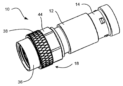
[0010] Figures 1-3 depict an exemplary coaxial cable connector 10
consistent with
embodiments described herein. As illustrated, connector 10 may include a
connector body
12, a locking sleeve 14, an annular post 16 (not visible in Fig. 1), and a
rotatable nut
assembly 18.
[0011] In one implementation, connector body 12 (also referred to as a
"collar") may
include an elongated, cylindrical member, which can be made from plastic,
metal, or any
suitable material or combination of materials. Connector body 12 may include a
forward end
20 operatively coupled to annular post 16 and rotatable nut 18, and a cable
receiving end 22
opposite to forward end 20. Cable receiving end 22 may be configured to
insertably receive
locking sleeve 14, as well as a prepared end of a coaxial cable in the forward
direction as
shown by arrow A in Fig. 2.
- 3 -
CA 02702700 2010-04-30
[0012] Locking sleeve 14 may include a substantially tubular body having a
rearward
cable receiving end 24 and an opposite forward connector insertion end 26,
movably coupled
to connector body 12. Upon assembly of connector 10, locking sleeve 14 may be
lockingly
axially moveable along the direction of arrow A toward the forward end 20 of
the connector
body 12 from a first position, as shown, for example, in Fig. 2 to a second,
axially advanced
position (not shown). When in the first position, locking sleeve 14 may be
loosely retained
in connector 10. When in the second position, locking sleeve 14 may be secured
within
connector 10.
[0013] As mentioned above, connector 10 may further include annular post 16
coupled to
forward end 20 of connector body 12. As illustrated in Fig. 2, annular post 16
may include a
flanged base portion 28 at its forward end for securing the post within
annular nut assembly
18. Annular post 16 may also include an annular tubular extension 30 extending
rearwardly
within body 12 and terminating adjacent rearward end 22 of connector body 12.
In one
embodiment, the rearward end of tubular extension 30 may include a radially
outwardly
extending ramped flange portion or "barb" 32 to enhance compression of the
outer jacket of
the coaxial cable and to secure the cable within connector 10. Tubular
extension 30 of
annular post 16, locking sleeve 14, and connector body 12 together define an
annular
chamber 34 for accommodating the jacket and shield of an inserted coaxial
cable.
[0014] As illustrated in Figs. 1-3, annular nut assembly 18 may be
rotatably coupled to
forward end 20 of connector body 12 for providing mechanical attachment of the
connector
to an external device via a threaded relationship. Consistent with
implementations
described herein, annular nut assembly 18 may include a modular configuration
that includes
a body portion 36 and a textured ring 38 coupled to body portion 36.
- 4 -
CA 02702700 2010-04-30
[0015] Body portion 36 may include a substantially tubular body having a
forward
portion 40 and a rearward portion 42, as illustrated in Figs. 3A and 3B.
Rearward portion 42
may be further configured to include an external angled surface portion 44
formed integrally
with body portion 36. External angled surface portion 44 may include a number
of angled
surfaces suitable for engagement by a wrench or similar torque application
device. Rearward
portion 42 may further include a textured ring engagement portion 46 for
lockingly receiving
textured ring 38. In one exemplary implementation, angled surface portion 44
may include a
substantially hexagonal (i.e., 6-sided) or double hexagonal (i.e., 12-sided)
configuration for
facilitating tightening/loosening engagement by an SAE (Society of Automotive
Engineers)
wrench or metric wrench, or any other suitable wrench or tool.
[0016] Textured ring engagement portion 46 may be configured to receive
textured ring
38 thereon. As illustrated in Fig. 3A, textured ring engagement portion 46 may
include
angled surfaces configured to allow textured ring 38 to be inserted thereon,
yet structured to
prevent or inhibit rotational movement of textured ring 38 relative to body
portion 36 upon
insertion. For example, flat surfaces may project forward from each of the
external angled
surfaces. The flat surfaces may be connected by curved surfaces having an
outside diameter
substantially similar to the inside diameter of textured ring 38. In such a
configuration, the
edges formed between the flat surfaces and the curved surfaces may operate to
prevent
rotation of textured ring 38 relative to body portion 36.
[0017] In another exemplary implementation, as illustrated in Fig. 3B,
textured ring
engagement portion 46 may include a keyed structure for engagement with a
mating keyed
structure on an interior of textured ring 38. For example, textured ring 38
may include a
keyed portion, such as grooves or notches 39, extending from its inside
diameter. Textured
- 5 -
CA 02702700 2010-04-30
ring engagement portion 46 may include a matching key receiving portion in its
outside
diameter for preventing textured ring 38 from rotating relative to body
portion 36 upon
assembly. For example, textured ring engagement portion 46 may include a
number of keyed
grooves 47 formed axially on an exterior surface. The interaction between
textured ring 38
and textured ring engagement portion 46 may prevent both axial and rotational
movement of
texture ring 38 relative to body portion 38.
[0018] Body portion 36 may further include an annular flange 48 configured
to fix nut
assembly 18 axially relative to annular post 16 and connector body 12. In one
implementation, a resilient sealing 0-ring 50 may be positioned between
annular nut
assembly 18 and connector body 12 to provide a water resistant seal between
connector body
12, annular post 16, and annular nut 18. Body portion 36 may include internal
threads 52 for
engaging matching external threads provided on a mating terminal.
[0019] As illustrated in Figs. 2 and 3, textured ring 38 may be
substantially cylindrical
and may include an inside diameter similar to an outside diameter of textured
ring
engagement portion 46. Textured ring 38 may include an external textured
surface
configured to facilitate hand tightening and loosening of nut assembly 18. For
example, the
textured surface may include a knurled pattern formed into an outer surface of
textured ring
38. In another implementation, textured ring 38 may include a grooved pattern
or a pattern
including one or more raise ridges, e.g., a pebbled or ridged pattern.
[0020] In exemplary implementations, textured ring 38 may be formed of any
suitable
material, such as metal, plastic, or any suitable material or combination of
materials.
Furthermore, textured ring 38 may be provided in a variety of different colors
or appearances
different from connector body 12 for the purposes of product differentiation
or marking. In
- 6 -
CA 02702700 2010-04-30
one implementation, body portion 36 may be formed of metal and textured ring
38 may be
formed of a plastic, resin, or rubber having a different visual appearance
from body portion
36.
[0021] During assembly, textured ring 38 may be inserted onto textured ring
engagement
portion 46 of body portion 36. As described above, the locking structure of
textured ring 38
and textured ring engagement portion 46 may facilitate insertion of textured
ring 38 onto
textured ring engagement portion 46 while preventing relative rotational
movement
therebetween.
[0022] In one implementation, textured ring 38 may be coupled to body
portion 36 via a
snap-fit or press-fit mechanism. As illustrated in Fig. 2, textured ring
engagement portion 46
may include a groove 54 for receiving a mating ring 56 in textured ring 38.
Upon assembly
of connector 10, ring 56 may be received in groove 54 and may prevent or
inhibit
disassembly of textured ring 38 from body portion 36.
[0023] In another exemplary implementation, textured ring 38 may be formed
of molded
plastic or plastic resin formed in place about textured ring engagement
portion 46 in an
overmolding procedure. In this implementation, textured ring 38 is not
inserted onto textured
ring engagement portion 46 during assembly.
[0024] Connector 10 may be supplied in the assembled condition, as shown in
the
drawings, in which locking sleeve 14 is pre-installed inside rearward cable
receiving end 22
of connector body 12. In such an assembled condition, a coaxial cable may be
inserted
through rearward cable receiving end 30 of locking sleeve 14 to engage annular
post 16 of
connector 10 in the manner described above. In other implementations, locking
sleeve 14
- 7 -
CA 02702700 2010-04-30
may be first slipped over the end of a coaxial cable and the cable (together
with locking
sleeve 14) may subsequently be inserted into rearward end 22 of connector body
12.
[0025] In either case, once the prepared end of a coaxial cable is inserted
into connector
body 12 so that the cable jacket is separated from the insulator by the sharp
edge of annular
post 16, locking sleeve 14 may be moved axially forward in the direction of
arrow A from
the first position to the second position. In some implementations, advancing
locking sleeve
14 from the first position to the second position may be accomplished with a
suitable
compression tool. As locking sleeve 14 is moved axially forward, the cable
jacket is
compressed within annular chamber 34 to secure the cable in connector 10. Once
the cable is
secured, connector 10 is ready for attachment to a port connector, such as an
F-81 connector,
of an external device.
[0026] To facilitate attachment of connector 10 to the port connector of an
external
device, the port connector may be inserted into the forward opening of annular
nut assembly
18. Subsequent hand tightening of nut assembly 18 via textured ring 38 or
wrench tightening
via angled surface portion 44 may cause the port connect and post 16 to move
axially
together, thereby facilitating electrical and RF communication therebetween.
[0027] The above-described connector may pass electrical and RF signals
typically found
in CATV, satellite, closed circuit television (CCTV), voice of Internet
protocol (VoIP), data,
video, high speed Internet, etc., through the mating ports (about the
connector reference
planes).
[0028] An annular nut assembly is provided that includes both a textured
portion suitable
for hand tightening and an angled portion suitable for wrench tightening.
Further, by
providing a modular nut assembly, manufacturing costs may be significantly
reduced. For
- 8 -
CA 02702700 2010-04-30
example, consistent with implementations described above, body portion 36 may
be
machined from a single piece of hexagonal stock, thereby avoiding additional
machining and
fabrication costs. In addition, the modular nature of the proposed nut
assembly may facilitate
color and/or appearance differentiation between the textured portion and the
connector body.
[0029] The foregoing description of exemplary implementations provides
illustration and
description, but is not intended to be exhaustive or to limit the embodiments
described herein
to the precise form disclosed. Modifications and variations are possible in
light of the above
teachings or may be acquired from practice of the embodiments.
[0030] For example, various features have been mainly described above with
respect to a
coaxial cables and connectors for securing coaxial cables. In other
implementations, features
described herein may be implemented in relation to other cable or interface
technologies.
For example, the coaxial cable connector described herein may be used or
usable with
various types of coaxial cable, such as 50, 75, or 93 ohm coaxial cable, or
other characteristic
impedance cable designs. In addition, the modular nut assembly described above
may be
used with any type of nut that may require hand and/or tool tightening.
[0031] Although the invention has been described in detail above, it is
expressly
understood that it will be apparent to persons skilled in the relevant art
that the invention may
be modified without departing from the spirit of the invention. Various
changes of form,
design, or arrangement may be made to the invention without departing from the
spirit and
scope of the invention. Therefore, the above mentioned description is to be
considered
exemplary, rather than limiting, and the true scope of the invention is that
defined in the
following claims.
- 9 -
CA 02702700 2010-04-30
[0032] For example, although the above description references a modular nut
assembly
for use in connection with a coaxial cable connector, it should be understood
that the
described modular nut assembly may be incorporated into a variety of
implementations, such
as other types of nuts, connectors, etc.
[0033] No element, act, or instruction used in the description of the
present application
should be construed as critical or essential to the invention unless
explicitly described as
such. Also, as used herein, the article "a" is intended to include one or more
items. Further,
the phrase "based on" is intended to mean "based, at least in part, on" unless
explicitly stated
otherwise.
- 10 -