Note: Descriptions are shown in the official language in which they were submitted.
CA 02702876 2015-07-15
1
FLOOR PANEL
This invention relates to a floor panel.
More particularly, it relates to a floor panel comprising coupling parts at
least at two opposite
sides, in the form of a male coupling part and a female coupling part,
respectively, which allow
to connect two of such floor panels to each other at the aforementioned sides
by providing
one of these floor panels with the pertaining male coupling part, by means of
a downward
movement, in the female coupling part of the other floor panel, such that
thereby at least a
locking in horizontal direction is obtained.
Couplings allowing to couple two floor panels to each other by joining one
floor panel with a
downward movement into the other, in practice are subdivided into two kinds,
namely a first
kind wherein the coupling parts exclusively provide for a horizontal locking,
without any
presence of a locking in vertical direction, and a second kind wherein a
horizontal as well as a
vertical locking are provided for.
The couplings of the first kind are also known as so-called "drop-in" systems.
Floor panels
equipped with those at two opposite sides are known, amongst others, from CA
991.373
and JP 07-300979. As is evident from these patent documents, such "drop-in"
systems
often are only applied at a first pair of opposite sides of the floor panels,
whereas then at
the second pair of opposite sides, coupling parts are applied which, in the
coupled
condition of two floor panels, provide for a vertical as well as a horizontal
locking and which
allow that two of such floor panels can be coupled to each other by means of
an angling
movement. Floor panels with such a combination of coupling parts offer the
advantage that
they can be easily installed successively in rows, simply by coupling each new
floor panel
to be installed to the preceding row of floor panels by means of the angling
movement and
by providing for, when angling it down, that such floor panel simultaneously
also engages
in an already installed preceding floor panel of the same row. Thus, the
installation of such
floor panel only requires an angling and putting-down movement, which is a
CA 02702876 2010-04-15
WO 2009/066153
PCT/1B2008/003133
2
particularly user-friendly installation technique.
A disadvantage of floor panels with such coupling parts consists in that due
to the
fact that there is no locking in vertical direction, height differences
between the
coupled floor panels may arise at the top surface. Thus, for example, such
floor
panels in a first or last row of a floor covering may turn back upward from
their flat
position, if they are not held down by a skirting board or the like. Even if
such floor
panels are provided with a "drop-in" system at only one pair of sides, while
being
locked in horizontal as well as vertical directions at their other pair of
sides in
respect to adjacent floor panels, height differences may occur between
adjacent
floor panels at the sides coupled by the "drop-in" system, amongst others,
when
two adjacent floor panels are loaded differently, or when one floor panel
should
warp and bend somewhat in respect to the other.
Couplings of said second kind, also named "push-lock" systems, try to remedy
the
aforementioned disadvantage by also providing a vertical locking. Such so-
called
"push-lock" systems may be divided into two different categories, namely one-
piece embodiments and embodiments comprising a separate locking element,
which is made as an insert, whether or not fixedly attached to the actual
floor
panel.
One-piece embodiments are known, amongst others, from the patent documents
DE 29924454, DE 20008708, DE 20112474, DE
102004001363,
DE 102004055951, EP 1.282.752 and EP 1.350.904. The known one-piece
embodiments have the disadvantage that they are working relatively stiff and a
good joining of two floor panels can not always be guaranteed.
Embodiments comprising a separate locking element which assists in a vertical
and possibly also horizontal locking between two coupled floor panels, are
known,
amongst others, from the patent documents DE 202007000310, DE 10200401363,
DE 102005002297, EP 1.159.497, EP 1.415.056B1, EP
1.818.478,
WO 2004/079130, WO 2005/054599, WO 2006/043893, WO 2006/104436,
WO 2007/008139, WO 2007/079845 and SE 515324. The use of a separate
locking element offers the advantage that the material thereof is independent
of
the actual floor panel and thus can be chosen in an optimum manner in function
of
the application. Thereby, such inserts may be made of synthetic material or
metal,
CA 02702876 2015-07-15
3
whereby relatively sturdy, however, still easily movable locking portions can
be realized,
which, with a minimum contact surface, can take up relatively large forces.
According to one aspect of the present invention, there is provided a floor
panel comprising, at
least at two opposite sides, coupling parts with which two of such floor
panels can be coupled
to each other; wherein the coupling parts form a horizontally active locking
system and a
vertically active locking system; wherein the horizontally active locking
system comprises a
male part and a female part, which enable connection between first and second
floor panels at
said sides by providing one of the floor panels with the respective male part,
by means of a
downward movement, in the female part of the other floor panel; wherein the
vertically active
locking system comprises a locking element, which is provided in the form of
an insert in one
of the sides concerned; wherein the locking element comprises at least a
pivotable lock-up
body; wherein the lock-up body at a first extremity has an outer peripheral
surface forming a
stop-forming locking portion arranged to abut a locking surface of the first
floor panel when the
first and second floor panels are coupled; wherein the pivotable lock-up body
has a second
extremity opposite from said first extremity forming an outer peripheral
surface including a
support portion arranged to abut and rotate against a support surface of the
second floor
panel as the stop-forming locking portion of the lock-up body is brought into
engagement with
the locking surface of the first panel;
wherein said support portion mainly defines a local pivot zone, said pivotable
lock-up
body being angularly movable with respect to said pivot zone, the support
portion is rotatable
about a support point defined along a vertical line as the first and second
panels are brought
into a coupled condition, the locking portion defines a contact point arranged
for abutment
against the first floor panel, and the contact point is displaced from at
least a first position to at
least a second position as the first and second panels are brought into
engagement, wherein
the second position is closer to the vertical line than the first position.
According to another aspect of the present invention, there is also provided a
floor panel
comprising, at least at two opposite sides, coupling parts with which two of
such floor panels
can be coupled to each other; wherein the coupling parts form a horizontally
active locking
system and a vertically active locking system; wherein the horizontally active
locking system
comprises a male part and a female part, which enable connection between first
and second
floor panels at said sides by providing one of these floor panels with the
respective male part,
by means of a downward movement, in the female part of the other floor panel;
wherein the
CA 02702876 2015-07-15
3a
vertically active locking system comprises a locking element, which is
provided in the form of
an insert in one of the sides concerned; wherein the locking element comprises
at least a
pivotable lock-up body; wherein the lock-up body at a first extremity has an
outer peripheral
surface forming a stop-forming locking portion arranged to abut a locking
surface of the first
floor panel when the first and second floor panels are coupled; wherein the
pivotable lock-up
body has a second extremity opposite from said first extremity forming an
outer peripheral
surface including a support portion arranged to abut and rotate against a
support surface of
the second floor panel as the stop-forming locking portion of the lock-up body
is brought into
engagement with the locking surface of the first panel;
wherein said support portion mainly defines a local pivot zone, said pivotable
lock-up
body being angularly movable with respect to said pivot zone; and wherein the
lock-up body,
between the locking portion and the support portion, in itself is free from
hinge portions and
bending sections, the support portion is rotatable about a support point
defined along a
vertical line as the first and second panels are brought into a coupled
condition, the locking
portion defines a contact point arranged for abutment against the first floor
panel, and the
contact point is displaced from at least a first position to at least a second
position as the first
and second panels are brought into engagement, wherein the second position is
closer to the
vertical line than the first position.
According to another aspect of the present invention, there is also provided a
floor panel
comprising, at least at two opposite sides, coupling parts with which two of
such floor panels
can be coupled to each other; wherein the coupling parts form a horizontally
active locking
system and a vertically active locking system; wherein the horizontally active
locking system
comprises a male part and a female part, which enable connection between first
and second
floor panels at said sides by providing one of these floor panels with the
respective male part,
by means of a downward movement, in the female part of the other floor panel;
wherein the
vertically active locking system comprises a locking element, which is
provided in the form of
an insert in one of the sides concerned; wherein the lock-up body at a first
extremity has an
outer peripheral surface forming a stop-forming locking portion arranged to
abut a locking
surface of the first floor panel when the first and second floor panels are
coupled; wherein the
pivotable lock-up body has a second extremity opposite from said first
extremity forming an
outer peripheral surface including a support portion arranged to abut and
rotate against a
support surface of the second floor panel as the stop-forming locking portion
of the lock-up
body is brought into engagement with the locking surface of the first panel;
and wherein the
CA 02702876 2015-07-15
3b
lock-up body, between the locking portion and the support portion, in itself
is free from hinge
portions and bending sections; wherein the second extremity is in the form of
a free extremity,
wherein the support portion, in the coupled condition of the first and second
floor panels, is
supported in a vertical as well as in a proximal direction with respect to the
floor panels, the
support portion is rotatable about a support point defined along a vertical
line as the first and
second panels are placed into a coupled condition, the locking portion defines
a contact point
arranged for abutment against the first floor panel, and the contact point is
displaced from at
least a first position to at least a second position as the first and second
panels are brought
into engagement, wherein the second position is closer to the vertical line
than the first
position.
According to another aspect of the present invention, there is also provided a
floor panel
comprising, at least at two opposite sides, coupling parts with which two of
such floor panels
can be coupled to each other; wherein the coupling parts form a horizontally
active locking
system and a vertically active locking system; wherein the horizontally active
locking system
has a male part and a female part, which enable connection between first and
second floor
panels at said sides by providing one of the floor panels with the pertaining
male part, by
means of a downward movement, in the female part of the other floor panel;
wherein the
vertically active locking system comprises a locking element, which is
provided in the form of
an insert in one of the respective sides; wherein the locking element
comprises at least a
pivotable lock-up body; wherein the lock-up body at a first extremity has an
outer peripheral
surface forming a stop-forming locking portion arranged to abut a locking
surface of the first
floor panel when the first and second floor panels are coupled; wherein the
pivotable lock-up
body has a second extremity opposite the first extremity forming an outer
peripheral surface
including a support portion arranged to abut and rotate against a support
surface of the
second floor panel as the stop-forming locking portion of the lock-up body is
brought into
engagement with the locking surface of the first panel wherein the support
portion mainly
defines a local pivot zone, said pivotable lock-up body being angularly
movable with respect to
the pivot zone; and wherein the vertically active locking system comprises a
tensioning
system, which is formed by a cam surface formed at the first extremity of the
locking portion of
the lock-up body, which cam surface, in coupled condition, provides a wedge
effect against
the opposite locking portion of the coupled floor panel, the support portion
is rotatable about a
support point defined along a vertical line as the first and second panels are
placed into a
coupled condition, the locking portion defines a contact point arranged for
abutment against
CA 02702876 2015-07-15
3c
the first floor panel, and the contact point is displaced from at least a
first position to at least a
second position as the first and second panels are brought into engagement,
wherein the
second position is closer to the vertical line than the first position.
According to another aspect of the present invention, there is also provided a
floor panel,
comprising, at least at two opposite sides, coupling parts with which two of
such floor panels
can be coupled to each other; wherein the coupling parts form a horizontally
active locking
system and a vertically active locking system; wherein the horizontally active
locking system
has a male part and a female part, which enables connection between first and
second floor
panels to each other at the aforementioned sides by providing one of these
floor panels with
the pertaining male part, by means of a downward movement, in the female part
of the other
floor panel; wherein the vertically active locking system comprises a locking
element, which is
provided in the form of an insert in one of the respective sides; and wherein
the locking
element includes at least a pivotable lock-up body and a material part acting
as a hinge for the
lock-up body, said hinge material part being formed of a first material more
flexible and
bendable than a second material from which the lock-up body is formed outside
of the hinge
material part;
the first and second materials being different from one another.
According to another aspect of the present invention, there is also provided a
floor panel,
comprising, at least at two opposite sides, coupling parts with which two of
such floor panels
can be coupled to each other; wherein the coupling parts form a horizontally
active locking
system and a vertically active locking system; wherein the horizontally active
locking system
has a male part and a female part, which enables connection between first and
second floor
panels to at said sides by providing one of the floor panels with the
pertaining male part, by
means of a downward movement, in the female part of the other floor panel;
wherein the
vertically active locking system comprises a locking element, which is
provided in the form of
an insert in one of the sides concerned; wherein the locking element comprises
a lip-shaped
lock-up body; wherein the lock-up body at a first extremity has an outer
peripheral surface
forming a stop-forming locking portion arranged to abut a locking surface of
the first floor
panel when the first and second floor panels are coupled; wherein the
pivotable lock-up body
has a second extremity opposite from said first extremity forming an outer
peripheral surface
including a support portion arranged to abut and rotate against a support
surface of the
second floor panel as the stop-forming locking portion of the lock-up body is
brought into
CA 02702876 2015-08-27
3d
engagement with the locking surface of the first panel; wherein the support
portion is rotatable
about a support point defined along a vertical line as the first and second
panels are placed
into a coupled condition, the locking portion defines a contact point arranged
for abutment
against the first floor panel, and the contact point is displaced from at
least a first position to at
least a second position as the first and second panels are brought into
engagement, wherein
the second position is closer to the vertical line than the first position;
and wherein the male
and the female part are configured such that two of such floor panels can be
joined into each
other at the sides concerned by shifting them with the sides concerned towards
each other in
the same plane.
According to another aspect of the present invention, there is also provided a
floor panel
comprising, at least at two opposite sides, coupling parts with which two of
such floor panels
can be coupled to each other at the respective edges; wherein the coupling
parts form a
horizontally active locking system and a vertically active locking system;
wherein at least one
of the locking systems comprises a locking element, in the form of a separate
insert at one of
the respective edges; wherein the locking element comprises at least a movable
lock-up body;
wherein the lock-up body at a first extremity has an outer peripheral surface
forming a stop-
forming locking portion arranged to abut a locking surface of the first floor
panel when the first
and second floor panels are coupled;
wherein the movable lock-up body has a second extremity opposite from said
first
extremity forming an outer peripheral surface including a support portion
abutting and
rotatable against a support surface of the second floor panel to bring the
stop-forming locking
portion of the lock-up body into engagement with the locking surface of the
first panel; and
wherein the locking element comprises a synthetic material strip which, viewed
in cross-
section, comprises at least two zones of materials with different material
characteristics;
wherein the lock-up body is attached directly or indirectly to a material part
pertaining
to the locking element or is made in one piece therewith, which enables an
elastic movement
of the lock-up body, wherein the material part comprises a first material,
which as such is
more flexible and bendable than a second material from which the lock-up body
is formed
outside of the first material part; wherein the first and second materials are
different from one
another.
According to another aspect of the present invention, there is also provided a
floor panel,
CA 02702876 2015-08-27
3e
said floor panel having a first pair of opposite sides and a second pair of
opposite
sides;
said floor panel being rectangular and oblong and said first pair of opposite
sides
forming the short sides and said second pair of opposite sides forming the
long sides;
said floor panel at the first pair of opposite sides comprising coupling parts
with which
two of such floor panels can be coupled to each other;
wherein these coupling parts form a horizontally active locking system and a
vertically
active locking system;
wherein the horizontally active locking system has a male part and a female
part,
which allow to connect two of such floor panels to each other at the
respective first sides by
providing one of these floor panels with the pertaining male part, by means of
a downward
movement, in the female part of the other floor panel; and
wherein the vertically active locking system comprises a locking element,
which is
provided in the form of an insert in a distal face of the side which is
provided with the male
part;
said floor panel at the second pair of opposite sides comprising coupling
parts allowing
a connection with a similar panel at least by means of a pivoting movement,
said connection
providing a vertical as well as horizontal locking effect between the coupled
panels;
said coupling parts at said first and second pair of opposite sides being
configured
such that such panel at a long side by means of said pivoting movement can be
coupled to a
similar panel in a previous row, whereas simultaneously, the same panel, due
to the
downward movement engages at one of its short sides with a preceding panel in
the same
row;
wherein said locking element consists of a synthetic material strip provided
in a recess;
wherein said locking element comprises a lock-up body which is formed as a
pivotable
part, said lock-up body having an upward directed extremity in the form of a
free end that can
be rotated outward, said free end forming a locking portion which can co-
operate with a
locking portion of a similar coupled floor panel;
wherein said sides of said first pair of sides are realized in such a manner
that two of
such panels at these sides also can be locked or unlocked, or both locked and
unlocked by
mutually angling them into each other, out of each other, respectively; and
wherein the male part and the female part comprise cooperating contact
surfaces,
wherein the contact surface of the female part is upwardly inclined in a
distal direction.
CA 02702876 2015-08-27
,
3f
According to another aspect of the present invention, there is also provided a
floor panel
comprising,
at least at two opposite sides,
coupling parts with which two of such floor panels can be coupled to each
other at the
respective edges;
wherein the coupling parts form a horizontally active locking system and a
vertically
active locking system;
wherein at least one of the locking systems comprises a locking element, in
the form of
a separate insert at one of the respective edges;
wherein the locking element comprises at least a movable lock-up body having
an
extremity acting as a locking portion which in the coupled condition of two of
such panels
cooperates with a locking portion of a similar coupled floor panel; and
wherein the locking element comprises a synthetic coextruded material strip,
comprising, seen in cross section, at least two co-extruded zones of materials
with different
material characteristics.
According to another aspect of the present invention, there is also provided a
floor panel,
wherein this floor panel is rectangular, either oblong or square, and has a
first pair of
opposite sides and a second pair of opposite sides;
wherein said floor panel, at said first pair of opposite sides, comprises
coupling parts
with which two of such floor panels can be coupled to each other; wherein
these coupling
parts form a horizontally active locking system and a vertically active
locking system; wherein
the horizontally active locking system has a male part and a female part,
which allow to
connect two of such floor panels to each other at the respective first pair of
opposite sides by
providing one of these floor panels with the pertaining male part, by means of
a downward
movement, in the female part of the other floor panel;
wherein said floor panel, at said second pair of opposite sides, comprises
coupling
parts which allow a mutual coupling between two of such floor panels at the
respective second
pair of opposite sides at least by means of a pivoting movement between two of
such floor
panels, which coupling provides a horizontal as well as a vertical locking
between two of such
floor panels;
CA 02702876 2015-08-27
3g
wherein said coupling parts of the first pair of opposite sides as well as of
the second
pair of opposite sides are configured such that the floor panel can be coupled
to a similar floor
panel in a previous row of installed floor panels at the respective second
pair of opposite sides
by means of said pivoting movement, whereas simultaneously the same floor
panel, by means
of said downward movement, can be coupled to a similar preceding floor panel
in the same
row of installed floor panels at the respective first pair of opposite sides;
wherein the vertically active locking system of the first pair of opposite
sides comprises
a locking element, which is provided in the form of an insert in one of the
sides of the first pair
of opposite sides, more particularly in a recess provided in one of these
sides;
wherein said locking element comprises at least a pivotable lock-up body;
wherein said
pivotable lock-up body, at one extremity, forms a stop-forming locking portion
which can
cooperate with a locking portion of a similar coupled floor panel; wherein
said pivotable lock-
up body extends over a height which is at least 40% of the height difference
between an
upper side of the floor panel and a lowermost point of the male part;
wherein said recess is bordered by at least an upper wall and a lower wall,
wherein the
wall which is situated closest to an extremity of said pivotable lock-up body
situated opposite
the extremity forming the stop-forming locking portion, extends distally
beyond said extremity
situated opposite the extremity forming the stop-forming locking portion; and
wherein said locking element is provided with an attachment portion, which
attachment portion
consists of an attachment body which, viewed in a cross-section perpendicular
to the
concerned sides, extends in a general flat direction, said attachment body
being provided in
the recess.
According to another aspect of the present invention, there is also provided a
floor panel,
wherein this floor panel is rectangular, either oblong or square, and has a
first pair of
opposite sides and a second pair of opposite sides;
wherein said floor panel, at said first pair of opposite sides, comprises
coupling parts
with which two of such floor panels can be coupled to each other; wherein
these coupling
parts form a horizontally active locking system and a vertically active
locking system; wherein
the horizontally active locking system has a male part and a female part,
which allow to
connect two of such floor panels to each other at the respective first pair of
opposite sides by
providing one of these floor panels with the pertaining male part, by means of
a downward
movement, in the female part of the other floor panel;
CA 02702876 2015-08-27
3h
wherein said floor panel, at said second pair of opposite sides, comprises
coupling
parts which allow a mutual coupling between two of such floor panels at the
respective second
pair of opposite sides at least by means of a pivoting movement between two of
such floor
panels, which coupling provides a horizontal as well as a vertical locking
between two of such
floor panels;
wherein said coupling parts of the first pair of opposite sides as well as of
the second
pair of opposite sides are configured such that the floor panel can be coupled
to a similar floor
panel in a previous row of installed floor panels at the respective second
pair of opposite sides
by means of said pivoting movement, whereas simultaneously the same floor
panel, by means
of said downward movement, can be coupled to a similar preceding floor panel
in the same
row of installed floor panels at the respective first pair of opposite sides;
wherein the vertically active locking system of the first pair of opposite
sides comprises
a locking element, which is provided in the form of an insert in one of the
sides of the first pair
of opposite sides, more particularly in a recess provided in one of these
sides;
wherein said locking element comprises at least a pivotable lock-up body;
wherein said
pivotable lock-up body, at one extremity, forms a stop-forming locking portion
which can
cooperate with a locking portion of a similar coupled floor panel; and wherein
said stop-
forming locking portion of the pivotable lock-up body is performed in the form
of a broadened
extremity of the pivotable lock-up body.
According to another aspect of the present invention, there is also provided a
floor panel,
wherein this floor panel is rectangular, either oblong or square, and has a
first pair of
opposite sides and a second pair of opposite sides;
wherein said floor panel, at said first pair of opposite sides, comprises
coupling parts
with which two of such floor panels can be coupled to each other; wherein
these coupling
parts form a horizontally active locking system and a vertically active
locking system; wherein
the horizontally active locking system has a male part and a female part,
which allow to
connect two of such floor panels to each other at the respective first pair of
opposite sides by
providing one of these floor panels with the pertaining male part, by means of
a downward
movement, in the female part of the other floor panel;
wherein said floor panel, at said second pair of opposite sides, comprises
coupling
parts which allow a mutual coupling between two of such floor panels at the
respective second
pair of opposite sides at least by means of a pivoting movement between two of
such floor
CA 02702876 2016-05-16
3i
panels, which coupling provides a horizontal as well as a vertical locking
between two of such
floor panels;
wherein said coupling parts of the first pair of opposite sides as well as of
the second
pair of opposite sides are configured such that the floor panel can be coupled
to a similar floor
panel in a previous row of installed floor panels at the respective second
pair of opposite sides
by means of said pivoting movement, whereas simultaneously the same floor
panel, by means
of said downward movement, can be coupled to a similar preceding floor panel
in the same
row of installed floor panels at the respective first pair of opposite sides;
wherein the vertically active locking system of the first pair of opposite
sides comprises
a locking element, which is provided in the form of an insert in one of the
sides of the first pair
of opposite sides, more particularly in a recess provided in one of these
sides;
wherein said locking element comprises at least a pivotable lock-up body;
wherein the
pivotable lock-up body, at one extremity, forms a stop-forming locking portion
which can
cooperate with a locking portion of a similar coupled floor panel; wherein
said locking element
is provided with an attachment portion; wherein a connection is formed between
the pivotable
lock-up body and the attachment portion, said connection being provided with
elastic and/or
bending properties which are different with respect to the lock-up body and
the attachment
portion, such that said connection is configured as a local hinge part; and
wherein said
pivotable lock-up body extends over a height which is at least 40% of the
height difference
between an upper side of the floor panel and a lowermost point of the male
part.
According to another aspect of the present invention, there is also provided a
floor panel,
wherein this floor panel is rectangular, either oblong or square, and has a
first pair of opposite
sides and a second pair of opposite sides;
wherein said floor panel, at said first pair of opposite sides, comprises
coupling parts
with which two of such floor panels can be coupled to each other; wherein
these coupling
parts form a horizontally active locking system and a vertically active
locking system; wherein
the horizontally active locking system has a male part and a female part,
which allow to
connect two of such floor panels to each other at the respective first pair of
opposite sides by
providing one of these floor panels with the pertaining male part, by means of
a downward
movement, in the female part of the other floor panel;
wherein said floor panel, at said second pair of opposite sides, comprises
coupling
parts which allow a mutual coupling between two of such floor panels at the
respective second
CA 02702876 2016-05-16
3j
pair of opposite sides at least by means of a pivoting movement between two of
such floor
panels, which coupling provides a horizontal as well as a vertical locking
between two of such
floor panels;
wherein said coupling parts of the first pair of opposite sides as well as of
the second
pair of opposite sides are configured such that the floor panel can be coupled
to a similar floor
panel in a previous row of installed floor panels at the respective second
pair of opposite sides
by means of said pivoting movement, whereas simultaneously the same floor
panel, by means
of said downward movement, can be coupled to a similar preceding floor panel
in the same
row of installed floor panels at the respective first pair of opposite sides;
wherein the vertically active locking system of the first pair of opposite
sides comprises
a locking element, which is provided in the form of an insert in one of the
sides of the first pair
of opposite sides, more particularly in a recess provided in one of these
sides;
wherein said locking element comprises at least a pivotable lock-up body;
wherein said
pivotable lock-up body, at one extremity, forms a stop-forming locking portion
which can
cooperate with a locking portion of a similar coupled floor panel; wherein
said pivotable lock-
up body, in a coupled condition of two of such floor panels, extends over a
height which is at
least 40% of the height difference between upper sides of the coupled floor
panels and a
lowermost point of the male part;
wherein said recess is bordered by at least an upper wall and a lower wall,
wherein the
wall which is situated closest to an extremity of said pivotable lock-up body
situated opposite
the extremity forming the stop-forming locking portion, extends distally
beyond said extremity
situated opposite the extremity forming the stop-forming locking portion; and
wherein said locking element is provided with an attachment portion, which
attachment
portion consists of an attachment body which, viewed in a cross-section
perpendicular to the
concerned sides, extends in a general flat direction, said attachment body
being provided in
the recess.
According to another aspect of the present invention, there is also provided a
floor panel,
wherein this floor panel is rectangular, either oblong or square, and has a
first pair of opposite
sides and a second pair of opposite sides;
wherein said floor panel, at said first pair of opposite sides, comprises
coupling parts
with which two of such floor panels can be coupled to each other; wherein
these coupling
parts form a horizontally active locking system and a vertically active
locking system; wherein
CA 02702876 2016-05-16
3k
the horizontally active locking system has a male part and a female part,
which allow to
connect two of such floor panels to each other at the respective first pair of
opposite sides by
providing one of these floor panels with the pertaining male part, by means of
a downward
movement, in the female part of the other floor panel;
wherein said floor panel, at said second pair of opposite sides, comprises
coupling
parts which allow a mutual coupling between two of such floor panels at the
respective second
pair of opposite sides at least by means of a pivoting movement between two of
such floor
panels, which coupling provides a horizontal as well as a vertical locking
between two of such
floor panels;
wherein said coupling parts of the first pair of opposite sides as well as of
the second
pair of opposite sides are configured such that the floor panel can be coupled
to a similar floor
panel in a previous row of installed floor panels at the respective second
pair of opposite sides
by means of said pivoting movement, whereas simultaneously the same floor
panel, by means
of said downward movement, can be coupled to a similar preceding floor panel
in the same
row of installed floor panels at the respective first pair of opposite sides;
wherein the vertically active locking system of the first pair of opposite
sides comprises
a locking element, which is provided in the form of an insert in one of the
sides of the first pair
of opposite sides, more particularly in a recess provided in one of these
sides;
wherein said locking element comprises at least a pivotable lock-up body
having a first
extremity and a second extremity opposite the first extremity; wherein said
pivotable lock-up
body, at the first extremity, forms a stop-forming locking portion which can
cooperate with a
locking portion of a similar coupled floor panel; and wherein the first
extremity is broader than
the second extremity;
wherein said locking element is provided with an attachment portion; and
wherein said locking element is configured such that, during said downward
movement, the pivotable lock-up body performs a pivoting movement, whereas the
attachment portion remains substantially stationary.
According to another aspect of the present invention, there is also provided a
floor panel,
wherein this floor panel is rectangular, either oblong or square, and has a
first pair of opposite
sides and a second pair of opposite sides;
wherein said floor panel, at said first pair of opposite sides, comprises
coupling parts
with which two of such floor panels can be coupled to each other; wherein
these coupling
CA 02702876 2016-05-16
31
parts form a horizontally active locking system and a vertically active
locking system; wherein
the horizontally active locking system has a male part and a female part,
which allow to
connect two of such floor panels to each other at the respective first pair of
opposite sides by
providing one of these floor panels with the pertaining male part, by means of
a downward
movement, in the female part of the other floor panel;
wherein said floor panel, at said second pair of opposite sides, comprises
coupling
parts which allow a mutual coupling between two of such floor panels at the
respective second
pair of opposite sides at least by means of a pivoting movement between two of
such floor
panels, which coupling provides a horizontal as well as a vertical locking
between two of such
floor panels;
wherein said coupling parts of the first pair of opposite sides as well as of
the second
pair of opposite sides are configured such that the floor panel can be coupled
to a similar floor
panel in a previous row of installed floor panels at the respective second
pair of opposite sides
by means of said pivoting movement, whereas simultaneously the same floor
panel, by means
of said downward movement, can be coupled to a similar preceding floor panel
in the same
row of installed floor panels at the respective first pair of opposite sides;
wherein the vertically active locking system of the first pair of opposite
sides comprises
a locking element, which is provided in the form of an insert in one of the
sides of the first pair
of opposite sides, more particularly in a recess provided in one of these
sides, wherein the
recess is bordered by at least an upper wall and a lower wall, and has a non-
uniform
thickness;
wherein said locking element comprises at least a pivotable lock-up body;
wherein the
pivotable lock-up body, at one extremity, forms a stop-forming locking portion
which can
cooperate with a locking portion of a similar coupled floor panel; wherein
said locking element
is provided with an attachment portion; wherein a connection is formed between
the pivotable
lock-up body and the attachment portion, said connection being provided with
elastic and/or
bending properties which are different with respect to the lock-up body and
the attachment
portion, such that said connection is configured as a local hinge part; and
wherein said
pivotable lock-up body, in a coupled condition of two of such floor panels,
extends over a
height which is at least 40% of the height difference between upper sides of
the coupled floor
panels and a lowermost point of the male part.
CA 02702876 2016-05-16
3m
According to another aspect of the present invention, there is also provided a
floor panel,
wherein the floor panel comprises, at least at two opposite sides, coupling
parts with which
two of such floor panels can be coupled to each other; wherein the coupling
parts form a
horizontally active locking system and a vertically active locking system;
wherein the
horizontally active locking system has a male part and a female part, which
allow to connect
two of such floor panels to each other by providing one of these floor panels
with the
pertaining male part, by means of a downward movement, in the female part of
the other floor
panel, the male and the female part being substantially made from the actual
panel material;
wherein the vertically active locking system comprises a locking element,
which is provided in
the form of an insert in one of the sides; wherein the locking element
comprises a lock-up
body, said lock-up body forming a stop-forming locking portion which can
cooperate with a
locking portion of a similar coupled floor panel; and wherein, in a coupled
condition of two of
such floor panels, the floor panels at their coupled sides are pressed towards
each other by
means of a tension force.
Other aspects, aims, embodiments, variants and/or advantages of the present
invention, all
being preferred and/or optional, are briefly summarized hereinbelow.
For example, the present invention also relates to floor panels which are
equipped with a
"push-lock" system of the aforementioned category, in other words, which
comprise a whether
or not fixedly attached, however, separately realized insert. The aim of the
invention consists
in a further optimization of these "push-lock" systems in floor panels. These
improvements
substantially consist of seven aspects, which will be discussed in the
following.
The first five aspects are specifically connected to floor panels of the type:
- which comprises, at least at two opposite sides, coupling parts with
which two of such
floor panels can be coupled to each other;
- wherein these coupling parts form a horizontally active locking
system and a vertically
active locking system;
- wherein the horizontally active locking system comprises a male part and a
female
part, which allow that two of such floor panels can be connected to each other
at the
aforementioned sides by providing one of these floor panels with the
pertaining male
part, by means of a downward movement, in the female part of the other floor
panel;
CA 02702876 2016-05-16
3n
- wherein the vertically active locking system comprises a locking element,
which is
provided in the form of an insert in one of the sides concerned;
- wherein this locking element comprises at least a pivotable lock-up
body; and
- wherein the lock-up body, at one extremity, forms a stop-forming locking
portion, which
can cooperate with a locking portion of a similar coupled floor panel.
Floor panels of this type are known, amongst others, from the figures 5-7, 8
and 9-11 of the
aforementioned EP 1.415.05661. In these known embodiments, the locking portion
realized in
the form of an insert consists of a synthetic material strip with an
elastically bendable lip, which,
during its bending, functions as a pivotable lock-up body. These known
embodiments show
the advantage that with a relatively simple construction, a so-called "push-
lock" connection
can be realized which is active over the entire length of the synthetic
material strip. However,
CA 02702876 2010-04-15
WO 2009/066153
PCT/1B2008/003133
4
practice has shown that this known embodiment is not always functioning
smoothly
and that tolerances in a realized coupling sometimes are difficult to keep
under
control.
According to its first five aspects, the present invention aims at floor
panels of the
aforementioned specific type, which are further improved in respect to the
aforementioned known embodiments. Thus, these improvements substantially
consist in five aspects, which can be applied separately or in any imaginable
combination.
To this aim, the invention according to a first aspect relates to a floor
panel of the
above-mentioned specific type, with the characteristic that the pivotable lock-
up
body, opposite from the extremity forming the locking portion, comprises a
support
portion, which is rotatable against a support surface pertaining to the floor
panel
concerned, and more particularly is rotatable in a seat. As the lock-up body
is
provided with a support portion which is rotatable against a support surface,
and
more particularly is rotatable in a seat, the rotational movement of the lock-
up body
is defined better than in the known embodiments, and a more precise coupling
can
be provided than, for example, in the case of an embodiment according to
figures
5-7, 8 and 9-11 of said EP 1.415.056B1. In this known embodiment, the
pivotable
lock-up body in fact is realized as a prolongation of an attachment portion,
whereby the hinge function occurs in the material of the insert, and the
precise
rotational movement is difficult to predict, which may lead to a less optimum
functioning.
According to a second independent aspect, the invention relates to a floor
panel of
the above-mentioned specific type, with the characteristic that the pivotable
lock-
up body, opposite to the extremity forming the locking portion, comprises a
support
portion and that the lock-up body, between the locking portion and the support
portion, in itself is free from hinge portions and bending sections. As the
lock-up
body is free from hinge portions and bending sections, possible influences
thereof
on the shape and length of the lock-up body are excluded and a fixed useful
length
of the lock-up body can be guaranteed, such that, amongst others, small
production tolerances can be maintained, allowing precise couplings. In
connection
therewith, it is thus preferred that the lock-up body is performed as a rigid
element.
CA 02702876 2010-04-15
WO 2009/066153 PCT/1B2008/003133
According to a third independent aspect, the invention relates to a floor
panel of
the above-mentioned specific type, with the characteristic that the pivotable
lock-
up body, opposite to the extremity forming the locking portion, comprises a
support
portion in the form of a free extremity, which, at least in vertical
direction, is
5 positively supported by a support portion pertaining to the floor panel.
As the
support portion is made as a free extremity, it does not experience influences
from
adjacent material portions in its support portion, which is beneficial for a
smooth
hinge motion of the lock-up body. By a free extremity is substantially meant
that
this simply is made as a protruding leg, without any further parts being
attached
thereto.
According to a fourth independent aspect, the invention relates to a floor
panel of
the above-mentioned specific type, with the characteristic that the lock-up
body is
rotatable around a rotation point, support point, respectively, and that the
locking
element comprises a press-on portion engaging at the lock-up body at a
distance
from the rotation point, support point, respectively. Thereby, it is possible
to exert a
suitable force with the press-on element against the pivotable lock-up body,
even if
this press-on element as such is relatively weak.
According to a fifth independent aspect, the invention relates to a floor
panel of the
above-mentioned specific type, with the characteristic that the vertically
active
locking system comprises a tensioning system which is formed by a cam surface
formed at the extremity of the locking portion of the lock-up body, which cam
surface, in coupled condition, provides for a wedge effect against the
opposite
locking portion of the coupled floor panel. Due to such configuration, the
lock-up
body, in coupled condition, always will settle well under the locking portion
of the
other floor panel. Due to small movements occurring when the floor panels are
being walked on, the lock-up body, due to the wedge effect, will crawl farther
under
the locking portion of the other floor panel, whereby an even sturdier
coupling is
obtained. It is noted that this fifth aspect can be applied for all forms of
rotatable
locking portions, and thus, for example, also for embodiments, such as known
from
EP 1.415.056B1.
According to a sixth independent aspect, the invention relates to a floor
panel
comprising, at least at two opposite sides, coupling parts with which two of
such
floor panels can be coupled to each other; wherein these coupling parts form a
CA 02702876 2010-04-15
WO 2009/066153
PCT/1B2008/003133
6
horizontally active locking system and a vertically active locking system;
wherein
the horizontally active locking system comprises a male part and a female
part,
which allow to connect two of such floor panels to each other at the
aforementioned sides by providing one of these floor panels with the
pertaining
male part, by means of a downward movement, in the female part of the other
floor
panel; and wherein the vertically active locking system comprises a locking
element, which is provided in the form of an insert in one of the sides
concerned;
with the characteristic that the locking element consists of a co-extruded
synthetic
material strip provided in a recess, which strip, viewed in cross-section, is
composed of two or more zones consisting of synthetic materials with different
features. In other words, there are at least two zones of materials with
different
material characteristics. However, it is not excluded that certain zones do
have the
same material characteristics.
The use of such co-extruded synthetic material strip offers the advantage that
the
features can be selected depending on the function which certain parts of such
strip have to fulfill. For example, certain parts, which have to exert a
pressure force
or tension force, can be realized in a rather elastic synthetic material,
whereas
parts which have to take up forces in an immobile manner, then better consist
of a
hard synthetic material. Preferably, then also use is made of synthetic
materials
with different flexibility, elasticity, respectively. Also, flexible synthetic
materials
may be applied in order to realize movable connections among different parts
of
the strip. According to still another possibility, by means of the coextrusion
zones
are realized which can provide for a better sealing, or which offer increased
friction
resistance. Summarized, it is so that the different synthetic materials are
applied in
function of the desired movability and/or the desired compressibility and/or
the
desired sealing effect.
It is clear that the sixth aspect extends to all "push lock" systems which
apply a
separate locking element which is provided or is to be provided in a recess in
the
edge of a floor panel, and is not exclusively restricted to locking elements
with a
pivotable lock-up body.
According to a seventh independent aspect, the invention relates to a floor
panel
comprising, at least at two opposite sides, coupling parts with which two of
such
floor panels can be coupled to each other; wherein these coupling parts form a
CA 02702876 2010-04-15
WO 2009/066153
PCT/1B2008/003133
7
horizontally active locking system and a vertically active locking system;
wherein
the horizontally active locking system has a male part and a female part,
which
allow to connect two of such floor panels to each other at the aforementioned
sides
by providing one of these floor panels with the pertaining male part, by means
of a
downward movement, in the female part of the other floor panel; wherein the
vertically active locking system comprises a locking element, which is
provided in
the form of an insert in one of the sides concerned; with the characteristic
that the
locking element consists of a synthetic material strip provided in a recess,
which
strip, in the coupled condition of two floor panels, comes into contact with
both
floor panels and thereby forms a seal, wherein between the upper side of the
floor
panel and the synthetic material strip also a seal is present at the panel
edges.
The importance and advantage of this aspect will become clear from the
following
detailed description.
It is noted that all forms of combinations of the aforementioned seven aspects
are
possible.
Various advantageous dependent characteristics further will be described by
means of the embodiments represented in the figures. All these dependent
characteristics do not necessarily have to be applied in the mutual
combinations as
shown in the figures. Each characteristic can be combined as such with one of
the
independent aspects; such inasmuch as such dependent characteristic is not
inconsistent with the characteristics of the respective independent aspect
itself.
It is noted that the present invention preferably is applied for embodiments
where
the locking element, made as an insert, substantially, and still better
exclusively,
serves as a locking element assisting in the vertical locking and, thus, not
in the
horizontal locking. The horizontal locking preferably exclusively is performed
by
means of parts, such as the aforementioned male part and female part, which
are
made from the actual panel material, more particularly are mechanically formed
therefrom. More particularly, the invention preferably relates to embodiments
wherein the insert is produced separately and then is mounted in an edge of an
actual floor panel, whether or not in a fixed manner.
More particularly, it is noted that the invention preferably is applied in
embodiments
where said locking element provides exclusively for an upward blockage, which
CA 02702876 2010-04-15
WO 2009/066153
PCT/1B2008/003133
8
means that this blockage prevents that the male part can come loose from the
female element in an upward direction, whereas blockages in the other
directions,
thus, in downward direction and in horizontal direction, are obtained by the
design
of the panel edges themselves, in other words, by the coupling parts
mechanically
formed in the material of the panel.
Preferably, the invention relates to embodiments wherein at least the lock-up
body,
and still better even the entire locking element made as an insert, is
realized
relatively local, which more particularly means that it is only present
between a first
and a second horizontal level, of which the first horizontal level is situated
at a
distance beneath the upper side of the coupled floor panels, whereas the
second
horizontal level is situated lower than the first, however, higher than the
lowermost
point of the male part. Subsidiary thereto, it is, however, still preferred
that said
lock-up element extends over a height which is at least 40% and still better
at least
50% of the height difference between the upper side of such coupled floor
panels
and the lowermost point of the male part. Using at least 40%, at least 50%,
respectively, of this height in combination with said location between said
first and
second level offers various advantages. An advantage of embodiments fulfilling
this consists in that a good compromise is achieved between sufficient
compactness from the point of view of the possibility of a smooth application
in the
edge of a floor panel and from the point of view of the costs, on the one
hand, and
sufficient extent in order to optimize construction and shape of the locking
element,
on the other hand. Still another advantage in respect to the known embodiments
of
floor panels with a comparable total thickness, however, wherein the height of
the
lock-up body does not fulfill said ratio of at least 40%, is that, at least in
the case of
a pivotable lock-up body, a smaller rotation of this lock-up body already
results in a
relatively large deviation at the free extremity, whereby a good locking can
be
obtained in a smooth manner. As a consequence thereof, mostly a locked
condition can be realized in which the lock-up element is standing relatively
upright
and extends under an angle with the vertical which is considerably smaller
than
45%, whereby the lock-up element offers a particularly solid locking. This
also
allows working with a lock-up body of which the protruding exterior side is
standing
relatively upright, whereby this body during coupling can be pushed aside more
smoothly by another panel. As the lock-up element in the locked condition is
standing very upright, it is also obtained that the contact points of the lock-
up body
with the connected floor panels are located close to the panel edges, which is
CA 02702876 2010-04-15
WO 2009/066153
PCT/1B2008/003133
9
beneficial for a good connection.
The present invention relates to embodiments wherein said locking element is
integrated in the male part, as well as to embodiments wherein said element is
integrated in the female part. In the case of integration in the male part,
the locking
element preferably is situated in the distal side of this part, although
integration in
another side is not excluded. In the case of integration in the female part,
the
locking element preferably is situated at the proximal side, although
integration in
another side is not excluded.
Preferably, the coupling parts of the floor panels of the invention also are
configured such that they can be uncoupled by means of a pivoting movement,
irrespectively according to which of the aforementioned aspects they are
realized.
According to a particular embodiment, the coupling parts further are
configured
such that coupling by means of an angling movement is possible, too.
According to another embodiment, the male and the female part of said floor
panels are configured such that said floor panels can be brought into each
other at
the sides concerned by shifting them towards each other, preferably even such
that this is possible by moving them towards each other in a substantially
same
plane, for example, by shifting a panel towards another over an underlying
surface.
The locking then preferably takes place by means of a snap-on connection,
wherein the hook-shaped part of the female part bends elastically during
joining.
According to still another variant, said floor panels are realized such at the
sides
concerned that, apart from locking by means of a downward movement, also a
locking by shifting the floor panels towards each other, as well as a locking
and/or
unlocking by angling the floor panels in mutual respect is possible.
It is noted that the configuration allowing that two floor panels at the same
edges
can be joined by means of a downward movement, thus, according to the "push-
lock" principle, as well as by a mutual shifting in the same plane, thus,
according to
the principle of "snap action by means of shifting in the same plane", also
more
generally forms a particularity, without this combination necessarily having
to be
combined with one of said seven aspects. Due to this, the invention, according
to
an eighth aspect, thus also relates to a floor panel comprising, at least at
two
CA 02702876 2010-04-15
WO 2009/066153 PC
T/IB2008/003133
opposite sides, coupling parts with which two of such floor panels can be
coupled
to each other; wherein these coupling parts form a horizontally active locking
system and a vertically active locking system; wherein the horizontally active
locking system has a male part and a female part, which allow that two of such
5 floor
panels can be connected to each other at said sides by providing one of
these floor panels with the pertaining male part, by means of a downward
movement, in the female part of the other floor panel; wherein the vertically
active
locking system comprises a locking element, which is provided in the form of
an
insert in one of the sides concerned; wherein this locking element comprises a
lip-
10 shaped
lock-up body; and wherein the lock-up body, at one extremity, forms a
stop-forming locking portion, which can cooperate with a locking portion of a
similar coupled floor panel; characterized in that the male part and the
female part
are configured such that two of such floor panels can be joined into each
other at
the sides concerned by shifting them with the sides concerned towards each
other
in the same plane. Hereby, the advantage is created that the installation
comfort of
such floor panels is considerably increased, as connecting by means of the
downward movement allows for a rapid assembly, whereas the possibility of
coupling together by shifting the floor panels towards each other offers the
advantage that they can also be coupled to each other at locations where no
downward movement is possible and solely coupling by shifting is possible,
such
as, for example, in the case that a floor panel partially must be provided
underneath an overhanging element, such as a door frame, and from this
position
still has to be coupled to another floor panel.
It is clear that the invention also relates to floor panels combining the
eighth aspect
with one or more of the preceding aspects.
Floor panels meeting the eighth aspect preferably also show one or more of the
following characteristics:
the coupling parts concerned are performed at the aforementioned
sides such, that they allow a locking and/or unlocking of two of such
floor panels in mutual respect by mutually angling them into each other,
out of each other, respectively;
in free condition, the lip-shaped lock-up body protrudes outward in an
inclined manner;
the lock-up body is provided in the proximal side of the female part;
CA 02702876 2010-04-15
WO 2009/066153
PCT/1B2008/003133
11
- the female part and the male part comprise contact surfaces at their
distal extremities, said surfaces being performed upwardly inclined in
distal direction;
- the lip-shaped lock-up body is a pivotable body.
According to a particularly preferred embodiment, the floor panels of the
eighth
aspect relate to rectangular, either oblong or square, panels, and a pair of
opposite
sides of said coupling parts is provided according to the eighth effect,
whereas the
other, second pair of opposite sides comprises coupling parts, which also can
provide for a vertical and horizontal locking, of which kind whatsoever,
however,
which still allow that two of such floor panels can be joined into each other
at the
last-mentioned sides by substantially shifting them with the sides concerned
towards each other in the same plane. This combination of possibilities offers
an
even higher comfort of installation in difficult situations. According to an
additional
preferred characteristic, the coupling parts at the second pair of opposite
sides
also are configured such that they allow angling the floor panels in and out
of each
other. Examples of such coupling parts are widely known from the state of the
art,
for example, from figure 23 of WO 97/47834.
According to still another particular embodiment, the coupling parts of the
eighth
aspect are applied at both pairs of sides.
Further, the invention according to a ninth aspect also relates to a floor
panel
comprising, at least at two opposite sides, coupling parts with which two of
such
floor panels can be coupled to each other at the respective edges; wherein
these
coupling parts form a horizontally active locking system and a vertically
active
locking system; wherein at least one of the locking systems comprises a
locking
element, which is provided in the form of a separate insert at one of the
edges
concerned; wherein this locking element comprises at least a movable lock-up
body; and wherein the lock-up body, at one extremity, forms a stop-forming
locking
portion, which can cooperate with a locking portion of a similar coupled floor
panel;
with the characteristic that the locking element consists of a synthetic
material strip
which, viewed in cross-section, is composed of at least two zones of materials
with
different material characteristics. By making use of a separate insert formed
of
different materials, the advantage is created that the different portions of
the insert
can be optimized in function of their purpose. So, for example, may the lock-
up
CA 02702876 2010-04-15
WO 2009/066153
PCT/1B2008/003133
12
body be realized relatively rigid in order to be able to adequately withstand
occurring forces, whereas one or more other portions, which must provide the
movability of the lock-up body, then as such are realized relatively flexible.
Preferably, the floor panel according to the ninth aspect further is
characterized in
that the lock-up body is attached directly or indirectly to a material part
pertaining
to the locking element or is made in one piece therewith, which allows an
elastic
movement of the lock-up body, wherein this material part consists of a
material
which as such is more flexible and bendable than the material of which the
lock-up
body basically is formed.
According to still another preferred characteristic, the aforementioned
material part
is performed as a local hinge part, with the advantage that a very precisely
defined
pivoting movement is obtained.
Herein, it is preferred that said material part forms a connection between the
lock-
up body and an attachment portion, wherein the lock-up body and the attachment
portion consist of material which is less flexible than said material part. In
this
manner, it is obtained that an adequate locking is created by means of the
relatively rigid lock-up body, whereas by means of the relatively rigid
attachment
portion a stable positioning of the locking element in a recess in the edge of
the
floor panel concerned is possible.
In a preferred embodiment of the ninth aspect of the invention, the attachment
portion consists of an attachment body which, viewed in cross-section, extends
in
a flat or rather flat direction, which means substantially in the plane of the
floor
panel, which attachment body is provided in a recess. Such attachment portion
, allows an adequate attachment, also when the invention is applied in
relatively thin
floor panels. Another advantage is that by somewhat altering the direction
with
which this attachment portion is applied in the floor panel, different
functioning
characteristics can be obtained and the engineer in this manner can provide
for an
optimization.
Also according to the ninth aspect, the floor panel will be characterized in
that the
lock-up body can be elastically angled out with an extremity; that the lock-up
body,
globally seen, forms an angle with the attachment portion; that the lock-up
body,
CA 02702876 2010-04-15
WO 2009/066153
PCT/1B2008/003133
13
with the extremity situated opposite to the extremity which can be angled out,
protrudes up to beyond the attachment portion; that said material part makes a
connection between said extremity protruding beyond the attachment portion and
an adjacent portion of the actual attachment portion; and that at the location
where
the lock-up body passes along the attachment portion, the distance between the
lock-up body and the attachment portion is smaller than the distance from the
protruding extremity of the lock-up body to the attachment portion. As will
become
clear from the further description, this offers various advantages.
In the most preferred embodiment, the locking element of the ninth aspect of
the
invention is formed by means of coextrusion.
The ninth aspect is particularly useful with floor panels of the type which is
characterized in that the horizontally active locking system comprises a male
part
and a female part, which allow that two of such floor panels can be connected
to
each other at said sides by providing one of these floor panels with the
pertaining
male part, by a downward movement, in the female part of the other floor
panel, in
other words, floor panels of the so-called push-lock type. However, it is
noted that
the ninth aspect is not restricted to this type of floor panels and in
principle can be
applied for each type of coupling for floor panels wherein a horizontally
active
locking system and vertically active locking system are applied, wherein in
one or
the other way a separate locking system is integrated. So, for example, it is
possible to integrate the ninth aspect in strip-shaped locking elements of the
type
such as known from WO 2006/104436, more particularly figures 9c, 9e and 9f.
It is clear that the characteristics of the ninth aspect also can be combined
with the
characteristics from the first eight aspects.
With the intention of better showing the characteristics of the invention,
hereafter,
as an example without any Iimitative character, several preferred embodiments
are
described, with reference to the accompanying figures, wherein:
Figure 1 schematically and in top plan view represents a floor panel
according to the invention;
Figure 2, at a larger scale, represents a cross-section according to line II-
II
in figure 1;
Figure 3 in cross-section represents two floor panels, which are made
CA 02702876 2010-04-15
WO 2009/066153
PCT/1B2008/003133
14
according to figure 2, in coupled condition;
Figures 4 and 5 represent the floor panels from figure 3 in two different
steps during the joining;
Figure 6, at a larger scale, represents the locking element applied in the
embodiment of figures 2 to 5;
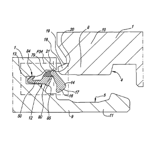
Figure 7, at a larger scale, represents the portion indicated by F7 in figure
2;
Figure 8 schematically represents how the locking element of figure 7 can
be mounted in a floor panel;
Figure 9 represents the locking element of figure 6 in cross-section and at a
strongly enlarged scale;
Figure 10, at a still larger scale, represents the uppermost extremity of the
locking element of figure 9, together with a locking portion with which it
comes into contact;
Figures 11 and 12 represent two variants;
Figures 13 and 14 represent two practical embodiments;
Figures 15 and 16 represent a particular embodiment;
Figure 17 represents still another embodiment of the invention;
Figures 18 and 19, at a larger scale, represent the portions indicated by
F18 and F19 in figure 17;
Figure 20 represents a particular fashion of coupling together two floor
panels made according to figure 17;
Figures 21 to 24 represent another four embodiments of the invention;
Figure 25 represents a number of floor panels which are realized according
to the invention;
Figure 26, at a larger scale, represents the portion indicated by F26 in
figure 25;
Figures 27 and 28 in cross-section represent another two particular
embodiments of the invention;
Figures 29 and 30 represent another two embodiments of the invention;
Figure 31 represents a schematic top view of floor panels, which are
coupled to each other according to figure 25;
Figure 32, in cross-section, represents still another embodiment of the
invention;
Figure 33 in cross-section represents still another embodiment of the
invention;
CA 02702876 2010-04-15
WO 2009/066153
PCT/1B2008/003133
Figure 34, at a larger scale, represents the portion indicated by F34 in
figure 33;
Figures 35 to 37 represent the part from figure 34 for various conditions
during coupling of two floor panels;
5 Figure 38
schematically represents how a locking element, made as an
insert, according to the invention can be attached in the edge of a floor
panel;
Figures 39 to 41, at a larger scale, represent cross-sections according to
lines XXXIX-XXXIX, XL-XL and XLI-XLI, respectively, in figure 38;
10 Figure 42
in cross-section represents still another embodiment of a
technique according to the invention, according to which a locking element
made as an insert can be attached in the edge of a floor panel;
Figure 43 represents a schematized cross-section according to line XLIII-
XLIII in figure 42.
As represented in figures 1 to 5, the invention relates to a floor panel 1
comprising,
at least at two opposite sides 2-3, coupling parts 4-5, with which two of such
floor
panels 1 can be coupled to each other.
As becomes clear from the coupled condition of figure 3, these coupling parts
4-5
comprise a horizontally active locking system 6 and a vertically active
locking
system 7. The horizontally active locking system 6 comprises a male part 8 and
a
female part 9, which allow to connect two of such floor panels 1 to each other
at
the aforementioned sides 2-3 by providing one of these floor panels 1 with the
pertaining male part 8, by means of a downward movement M, in the female part
9
of the other floor panel, which movement M is illustrated by means of two
different
positions in the figures 4 and 5.
The male part 8 is formed by a downward-directed extremity of a hook-shaped
part
10, whereas the female part 9 consists of a seat formed by means of an upward-
directed hook-shaped part 11.
The vertically active locking system 7 comprises a locking element 12, which,
in
the form of an insert, is provided in one of the sides concerned, in this
case, the
side 2, more particularly in a recess 13 provided to this aim. For
clarification, the
locking element 12, or in other words, thus, the insert, is illustrated in
separate
,
CA 02702876 2010-04-15
WO 2009/066153
PCT/1B2008/003133
16
condition in figure 6. As can be seen in this figure, this locking element 12
preferably is made as a strip. It is clear that this strip preferably extends
over the
entire or almost entire length of the side 2.
Preferably, this strip consists of synthetic material, however, the use of
other
materials to this aim is not excluded. Further, it is preferred that the strip
has a
continuous cross-section over its entire length, which renders it simple to
manufacture. In the case of a synthetic material strip, preferably use is made
of
PVC.
The enlarged view of figure 7 shows in greater detail how the strip is
attached in
the recess 13, which will be discussed further on.
In the represented example, the locking element 12 is composed at least of a
pivotable lock-up body 14 and a press-on portion 15. In the embodiment of
figure
6, the lock-up body 14 consists of the entire upright part, whereas the press-
on
portion 15 is formed by the portion inclinedly directed away.
The extremity 16 of the lock-up body 14, which can be rotated out, functions
as a
stop-forming locking portion 17, which can cooperate with a locking portion 18
of a
similar coupled floor panel 1. Herein, the locking portion 18 preferably is
formed by
a portion defining a stop-forming surface 19, which for this purpose is
present in
the side 3 and preferably is mechanically provided in the core of the floor
panel 1.
The functioning of the vertically active locking system can simply be deduced
from
the figures and relies on the principle that, as represented in figures 4 and
5, when
moving the floor panel concerned downward, the lock-up body 14 is elastically
folded inward by the contact with the edge of the other floor panel, after
which, as
soon as the floor panels have arrived in the same plane, the lock-up element
rotates back outward in order to position itself beneath the locking portion
18, such
that the coupled condition of figure 3 is created.
In accordance with the first aspect of the invention, the pivotable lock-up
body 14,
opposite from the extremity 16 forming the locking portion 17, comprises a
support
portion 20, which is rotatable against a support surface 21 pertaining to the
floor
panel 1 concerned, and more particularly in a seat 22. By the support portion
20 in
the embodiment of figures 2 to 10 thus the lowermost extremity 23 of the lock-
up
CA 02702876 2010-04-15
WO 2009/066153
PCT/1B2008/003133
17
body 14 is meant.
Further, the lock-up body 14 as such, between the locking portion 17 and the
support portion 20, in other words, between its extremities 16 and 23, is free
from
hinge portions and bending sections, such in accordance with the second aspect
of the invention. To this aim, thus, the lock-up body 14 is made relatively
thick and
preferably forms a rigid body, which means that the lock-up body 14 can not
undergo noticeable deformations between its extremities when pressures are
exerted hereupon, which usually may arise with "push-lock" couplings.
In accordance with the third aspect of the invention, the support portion 20
in the
represented embodiment is made as a free extremity, which is positively
supported
at least in vertical direction by a support portion 24, more particularly
support
surface 21, pertaining to the floor panel 1.
As can be clearly seen in figures 3 and 7, the support portion 20 of the lock-
up
body 14 preferably even is supported in two directions, at least in a coupled
condition of two floor panels 1, namely in vertical direction V, in this case,
thus,
downward, as well as in proximal direction P in respect to the floor panel 1,
this
latter by means of the lateral wall 25 of the seat 22.
In the represented example of figures 1 to 10, the floor panel 1 also
comprises a
stop-forming part 26, which, in a distal direction D in respect to the floor
panel 1,
forms a blockage for the support portion 20 or, thus, for the extremity 23 of
the
lock-up body 14. Thereby, a proper seat 22 can be formed, as a result of which
the
support portion 20 is sitting enclosed at three sides. In this manner, the
seat can
function as a rather precisely defined hinge point.
Generally, it can be stated that the locking element 12 preferably consists of
a strip
which is attached in a recess, in the represented example, thus, the recess
13, in
the floor panel 1 and that attachment provisions are present therein,
retaining the
strip in the recess. More particularly, it is preferred that the strip is snap-
fitted in the
recess and/or is sitting enclosed therein due to the design, which principle
also has
been applied in the embodiment of figures 1 to 10. As indicated in figure 7,
the
opening A of the recess is smaller than the largest dimension B of the strip,
with
the consequence that the latter automatically is retained in the recess 13.
CA 02702876 2010-04-15
WO 2009/066153
PCT/1B2008/003133
18
It is noted that other techniques for attaching or retaining such strip in the
recess
are possible, for example, by gluing, clamping or the like. A number of
advantages
are described in the following.
As schematically illustrated in figure 8, the strip or, thus, the locking
element 12
simply can be provided at a floor panel 1 by pressing it into the recess 13,
for
example, by means of a press-on portion or sliding block 27. Due to the
exerted
pressure, the strip is deformed and fits through opening A, after which it
regains its
original shape and becomes enclosed in the recess. More particularly, hereby
the
press-on portion 15 is bent in the manner as represented, in order to finally
bounce
into place.
The embodiment of figures 1 to 10 also applies the fourth aspect of the
invention,
namely in that the lock-up body 14 is rotatable around a rotation point,
support
point, respectively, and the press-on portion 15, at a distance from the
rotation
point, and more particularly at a distance D1 from the actual support point,
engages at the lock-up body 14. It is noted that by a "point", also a "zone"
can be
intended. Thus, a "support point" also may extend over a "zone".
As represented, the press-on portion 15 preferably consists at least, viewed
in
cross-section, of a leg adjoining to the rear side of the lock-up body 14,
which leg,
in free condition, extends obliquely in respect to the lock-up body 14, such
from a
location P1 situated between the two extremities of the lock-up body.
Preferably,
this leg also globally extends under an angle Al of less than 70 degrees in
respect
to the portion 28 of the lock-up body 14, which portion extends from said
location
P1 towards the locking portion 17.
The press-on portion 15 preferably consists of an elastic material, and more
particularly a material, which as such is more flexible than the material of
the lock-
up body 14. Preferably, this is also synthetic material, and in the most
preferred
embodiment, the press-on portion 15 is made in one piece with the lock-up body
14 by means of coextrusion. in the enlarged views of figures 6 and 9, the co-
extruded materials are represented with different shading.
Generally, it is noted that a locking element 12 in cross-section can only be
of
CA 02702876 2010-04-15
WO 2009/066153
PCT/1B2008/003133
19
small dimensions, in view of the fact that it must be integrated in the edge
of floor
panels having in practice a thickness which usually is less than 2 cm and in
many
cases is even less than 1 cm. Thus, the space then available for the locking
element 12 often only lies in the order of magnitude of 5 millimeters or less.
When
with such small dimensions different flexibilities must be incorporated into
the
locking element, the possibilities thus also are limited when one desires to
perform
this in a traditional manner by working with different thicknesses. By now
using
coextrusion according to the invention, a broader range of possibilities is
created
for incorporating different flexibilities, and thus also a different
elasticity, depending
on the intended effect.
The co-extruded materials may consist of the same or similar basic material
and,
for example, differ from each other only in that certain components are added
to
the one material, or certain components are present to a larger extent. In a
practical embodiment, the entire strip will consist of PVC, however, the more
flexible portion will be formed of PVC to which a larger quantity of
plasticizer is
added.
Also the location of the transition T between the co-extruded materials is of
importance. So, for example, this transition T, in the embodiment of figures 1
to 10,
preferably is situated at a distance X from the lock-up body. Thereby, a more
rigid
guiding portion remains present at the basis of the press-on portion 1, which
promotes the snap-on effect represented in figure 8.
In the embodiment of figures 1 to 10, the press-on portion 15, viewed in cross-
section, consists of only one leg.
In the embodiment of figures 1 to 10, a tensioning system 29 is integrated in
the
vertically active locking system, which tensioning system provides for that a
good
locking is created when the lock-up body 14 is angled out. By a tensioning
system,
here a system is intended which, when angling out the lock-up body 14,
additionally effects the approach among the locking portions 17 and 18.
As made clear in the larger representations of figures 9 and 1 0, in the
embodiment
of figures 1 to 10 to this aim use is made of a cam surface 30 formed at the
extremity 16 of the lock-up body 14, which cam surface, in coupled condition,
CA 02702876 2010-04-15
WO 2009/066153
PCT/1B2008/003133
provides a wedge effect against the opposite locking portion 18 of the coupled
floor
panel 1.
As indicated in figure 9, the cam surface 30, which consists at least of an
effective
5 contact zone 31 and possibly an entry zone 32, preferably extends over a
width B1
of at least 60% of the total width B2 of the lock-up body 14, which allows
providing
a gradual transition, which promotes a good wedge effect. Indeed, the entry
zone
32 preferably is somewhat steeper than the contact zone 31 and is intended to
provide for that the lock-up body 14 initially always will get smoothly
beneath the
10 surface 19.
Herein, the cam surface 30 preferably extends such that, as represented in
figures
9 and 10, according to a direction R, from the most outwardly situated edge 33
to
the most inwardly situated edge 34, the cam surface 30 shows an increasing
15 elevation E, such that the effective length of the lock-up body 14
increases for the
successive points of the cam surface according to the direction R. Herein, the
effective length is the distance between the locations where the lock-up body
comes into contact at the top and at the bottom.
20 The cam surface 30 and the surface 19 situated opposite thereof
preferably are
performed such that a displacement of the lock-up body 14 as a consequence of
tolerance differences results in a smaller or no displacement of the contact
zone,
more particularly the contact point, between both locking portions 17 and 18.
Preferably, therein the amount of the displacement of the contact zone or the
contact point is less than 50% of the size of the displacement of the cam
surface
30. This is illustrated in the following by means of figure 10. Herein, a
first condition
with a contact point in position Cl is represented in solid line. When, due to
settling, the surface 19 comes to lie somewhat higher, a condition is created
such
as represented in dashed line, wherein the contact point is displaced from a
position Cl to C2, and such according to the invention with a displacement VI,
which is noticeably smaller than the displacement V2 of the lock-up body 14.
The
advantage herein is that at all times, the displacement V2 is small, and it
can be
guaranteed that the contact always takes place within a certain distance 02
from
the upper edges of the floor panels 1 and a too far outward rotation, which
might
lead to a weak connection, is excluded. With tolerance differences, too, the
same
effect occurs. A first pair of floor panels may come into contact, for
example, as
CA 02702876 2010-04-15
WO 2009/066153
PCT/1B2008/003133
21
represented in solid line, whereas another pair, due to tolerance differences,
comes into contact as represented in dashed line. Due to a cam shape according
to the invention, it is then prevented that in the second case the contact
point C2
would be situated too far from the edges of the floor panels.
It is noted that, as represented in the figures, the locking portion 17 of the
lock-up
body 14 preferably is performed in the form of a broadened extremity of the
lock-
up body 14, due to which more space is offered for realizing a desired cam
surface
30.
The inclinations of the cam surface 30 and the surface 19 cooperating
therewith
preferably are realized such that they always define a tangent line L1-L2 in
their
contact zone, contact point C1-C2, respectively, the inclination angles of
which
with the horizontal, of which solely one is indicated in figure 10 by A2, are
less than
35 degrees.
Figures 11 and 12 show that the contact point C can also be displaced by the
selection of the shape of the surface 19 with which the lock-up body 14
cooperates
in coupled condition. It is noted that in coupled condition the connection
line L3
between the contact point C, or the middle of the contact zone when the
contact is
wider than a point, and a point where the lock-up body 14 is supported, is as
vertical as possible, as then, amongst others, horizontal force components,
which
might force the lock-up body back, remain limited. In this respect, it is also
preferred that the distance D3, at which the contact C, the center op the
contact
zone, respectively, is situated from the plane where the floor panels 1 fit
against
each other, is smaller than 1 mm and still better is smaller than 0.8 mm.
As represented in figures 2 and 7, the locking element 12 and the recess 13
are
performed such that this locking element 12, in the free, uncoupled condition
of the
floor panel 1 concerned, is sitting at least partially with its locking
portion 17 within
the recess 13. This offers, amongst others, the advantage that the strip, of
which
this locking element consists, when two floor panels 1 are joined into each
other by
means of a downward movement, in principle never can be pulled out of its seat
by
friction forces or for any other cause, due to which the good functioning
might be
disturbed.
CA 02702876 2010-04-15
WO 2009/066153
PCT/1B2008/003133
22
- It is clear that the coupling according to the invention can be applied in
combination with any floor panel 1.
Figure 13 shows the application of the embodiment represented in figures 1 to
10
in so-called prefabricated parquet, more particularly in so-called "engineered
wood". In this example, this relates to floor panels 1 which are constructed
from a
core 38 composed of strips 35-36-37, a top layer 39 of wood, as well as a
backing
layer 40 of wood. The top layer 39 consists of wood of a good quality, which
functions as a visible decorative layer. The backing layer 39 may consist of a
cheaper kind of wood. The strips 35 preferably also consist of a cheaper, for
example, soft kind of wood. However, it is preferred that at the extremities
of the
floor panels 1 strips 37-38 of a material are applied which is relatively
sturdy and
suited for providing the desired profile shapes therein, for example, milling
them
therein. In a practical embodiment, these strips 37-38 consist of MDF (Medium
Density Fiberboard) or HDF (High Density Fiberboard). It is clear that the
invention
can also be applied in combination with other forms of "engineered wood", for
example, wherein the core consists of a single continuous MDF/HDF board or of
a
plywood board.
Figure 14 represents an application in a laminate floor panel, in this case a
so-
called DPL (Direct Pressure Laminate), which, in a known manner, consists of a
core 41, for example, of MDF or HDF, a top layer 42 on the basis of one or
more
resin-impregnated layers, for example, a printed decor layer 43 and a so-
called
overlay 44, as well as a backing layer 45, which also consists of one or more
resin-
impregnated layers, wherein the whole is consolidated under heat and pressure.
Applications in other floor panels 1 are not excluded.
Figures 15 and 16 represent a particular embodiment, wherein in the side of
the
floor panel 1 situated opposite to the lock-up body 14, a recess 46 is
provided,
wherein, as can be seen in figure 16, in the longitudinal direction of the
edges a
rod 47 or the like can be introduced between the floor panels 1, in such a
manner
that the lock-up body 14 is pushed back and the floor panel concerned can be
lifted and thus can be uncoupled.
Figure 17 represents a variant of the invention, which differs from the above-
CA 02702876 2010-04-15
WO 2009/066153
PCT/1B2008/003133
23
described embodiment in a number of ways. So, for example, does the pivotable
lock-up body 14, next to the extremity 23 along which it is pivotable,
comprise a
tensioning system 48, which in this example, as illustrated in the enlarged
view of
figure 18, substantially consists of a cam 49 realized at said extremity 23,
which
cam, when the lock-up body 14 is being pivoted outward, also subjects this
lock-up
body 14 to an axial displacement V3 in the direction of the locking portion
17. It is
clear that the cam 49 to this aim must be realized with a suitable elevation,
which
can be determined by those skilled in art in function of the desired effect.
In figure
18, the elevation is illustrated by the distances D4 and D5, wherein D5 is
larger
than D4. The axial displacement V3 contributes to that the lock-up body 14,
during
coupling, initially can pivot outward in a smooth manner, however, as soon as
it is
partially pivoted out, rather quickly is seeking contact with the other floor
panel 1
before it can pivot outward too far.
In the embodiment of figure 17, also no distal stop-forming portion is
present, as a
result of which the locking element can be pressed into the recess 13 more
smoothly. As can be seen in figure 18, the lock-up body 14, instead of a
purely
pivoting movement, then possibly also may perform a tolling movement, whereby
it
possibly distances itself somewhat from the proximal lateral wall 25, however,
due
to settling of the whole when the floor is walked upon, or under the influence
of
other forces, indeed can take place against this wall again.
In the embodiment of figure 17, the locking element also is provided with an
attachment portion 50 especially provided for this purpose, which portion in
this
case is performed as a clamped part. As clearly represented in figure 19, the
clamping action herein is obtained by an elastic bending and/or deformation of
the
attachment portion 50.
Figure 17 also shows that the female part 9 can be performed with a relatively
low
hook-shaped part 10 and further may have such a shape that two of such floor
panels 1 can be brought into each other at the respective edges also by
sliding
them towards each other, whether or not assisted by the fact that the hook-
shaped
part 11 possibly is elastically bendable. This manner of joining is
illustrated in
figure 20. Herein, two possibilities can occur. When the floor panels 1 are
held in
the same plane and are moved towards each other in this manner, such as
indicated by arrow S1, the hook-shaped part Ills forced to bend out
elastically
CA 02702876 2010-04-15
WO 2009/066153
PCT/1B2008/003133
24
downward. When the floor panels 1 have been slid with their upper edges
against
each other, the lock-up body 14 automatically comes into the locking position,
whereas the bent-out hook-shaped part 11 also bounces back and comes to sit
behind the male part 8. When the floor panel 1 comprising the lock-up body 14
at
its edge to be coupled is freely movable in height, then during joining a
movement
according to arrow S2 will take place, wherein the male part 8 arcuately
slides over
the hook-shaped part 11 in order to finally drop until a locking is obtained.
Of
course, also combinations of both movements may take place.
As schematically indicated in figure 17 by arrow S3, the represented coupling
parts
also allow that two of such panels can be coupled and/or uncoupled by an
angling
movement, such by applying a suitable height of the hook-shaped part 11 and/or
a
suitable inclination of the contact surfaces 51-52.
It is clear that all characteristics described above by means of figures 17 to
20
optionally can also be integrated into other embodiments of the invention.
It is noted that the locking element 12 according to the invention can be
taken up
into the sides 2-3 to be coupled at various locations. For example, figures 21
to 23
represent three embodiments, wherein this element is provided at the female
part
9 instead of the male part 8, whereas figure 24 represents an embodiment,
wherein the locking element 12 is provided in the edge region and thus not in
the
actual seat where the male part fits into the female part.
The embodiment of figure 22 shows that the press-on portion 15 also may have a
bent or folded-over shape.
,
Figure 23 represents that the locking element can also be attached in the
recess
13 by means of glue 53, possibly by means of a portion especially provided for
this
purpose, such as an attachment lip 54, which, for example, is in connection
with
the press-on portion 15.
It is noted that the locking element 12, or, thus, the strip, as such can be
provided
with one or more elastic bending zones, which either form a connection between
the actual press-on portion 15 and the lock-up body 14, or a connection
between
several portions of the press-on portion 15, or still between other portions.
Such
CA 02702876 2010-04-15
WO 2009/066153
PCT/1B2008/003133
bending zones allow obtaining the desired mutual movability among the
composing parts. The embodiment of figure 23 is an example thereof, wherein
two
flexible bending zones 15A are provided, between the attachment lip 54 and the
press-on part 15 on the one hand and the press-on part 15 and the lock-up body
5 14 on the other hand.
Preferably, such bending zones 15A are formed by coextrusion during the
manufacture of the locking element 12.
10 In general, it is preferred that a locking element according to the
invention provides
for a stable support in vertical direction, whereas in horizontal direction,
thus, in the
pivoting direction, a flexible movability is effected. The application of co-
extruded
parts assists therein.
15 In the case of rectangular floor panels, either oblong or square, it is
clear that
coupling parts can also be provided at the second pair of opposite sides,
which
coupling parts, in coupled condition, preferably also offer a horizontal as
well as a
vertical locking. These coupling parts at the second pair of sides also can be
performed as a "push-lock" coupling, whether or not in accordance with the
20 present invention. Preferably, however, at the second pair of sides
coupling means
will be applied allowing a mutual coupling by means of a pivoting movement
between two floor panels to be coupled and/or by means of a shifting movement
resulting in a snap-on connection. Such coupling parts are widely known from
the
state of the art and are described, for example, in WO 97/47834.
In the most preferred embodiment, at the second pair of sides 55-56 coupling
parts
57-58 will be applied allowing at least a connection by means of a pivoting
movement, as this allows installing the floor panels, as illustrated in
figures 25 and
26, in a simple manner. A new floor panel 1C to be installed then can be
simply
angled at its side 55 into the preceding row of floor panels 1A, and such just
next
to a preceding floor panel 1B in the same row. When being angled down, the
male
part of the new floor panel 1C to be installed then automatically engages in
the
female part of the preceding floor panel 1B, without the necessity of
performing
another operation. In the case of oblong floor panels 1, thus, it is preferred
that the
so-called "push-lock" connection then is situated at the short sides.
CA 02702876 2010-04-15
WO 2009/066153
PCT/1B2008/003133
26
Figure 27 represents an example of the seventh aspect of the invention.
According
to this aspect, the locking element 12 consists of a synthetic material strip
provided
in a recess 13, which strip, in the coupled condition of two floor panels 1,
comes
into contact with both floor panels 1 and thereby forms a seal, wherein
between
the upper side 59 of the floor panel 1 and the synthetic material strip also a
seal
60-61 is present at the panel edges 62-63. The intention herein is that the
synthetic material strip is applied as a seal against the infiltration of
water and
thereby offers at least a barrier which at least decelerates and preferably
completely blocks the possible infiltration of water in between the coupling
parts 4-
5, whereas the seal 60, 61, respectively, at the panel edges is intended for
protecting the panel material 64, which mostly is based on wood, as such
against
the penetration of water. Possible water which might infiltrate in between two
floor
panels 1 then can not or only with difficulty infiltrate up to beneath the
floor panels
1, whereby the risk of rotting and mould formation beneath the floor panels 1
is
restricted, whereas this water also can not penetrate into the floor panels 1
themselves and thus a damage at the floor panels 1 themselves, for example, by
swelling, is excluded. The moisture present above the synthetic material strip
can
evaporate in due course.
In the represented example, the seal against moisture penetration is formed at
one
side 3 by the contact 65 and at the other side 2 by one or more of the
contacts 66,
67 or 68. In order to guarantee a better sealing, the locking element can be
provided with one or more sealing material portions 69, for example, of a
relatively
soft synthetic material or rubber, which are present at the location of the
contacts
65-66-67-68 at the locking element 12. These sealing material portions can be
provided at the synthetic material strip in any manner. In a practical
embodiment,
this will be performed by means of coextrusion.
The seals 60-61 at the panel edges 62-63 may have any form. As represented,
they are formed, for example, by an impregnation layer or a covering layer,
such
as a lacquer or varnish layer. They extend from at the top layer downward,
each
time at least up to one of the locations where said contacts are realized.
According
to a not represented variant, such seal also may consist in that the top layer
extends up to a location where one of the contacts is realized, for example,
by
applying a top layer which extends over the upper edges downward.
CA 02702876 2010-04-15
WO 2009/066153 PCT/1B2008/003133
27
According to the seventh aspect, it is intended that the top layer also is
waterproof.
Moreover, it then may consist of any material, such as a laminate, a film, a
lacquer
layer, a water-repellent or waterproof print, a varnish or the like.
It is clear that in this manner both the infiltration of water as well as the
penetration
of water into the panel edges is avoided.
It is noted that floor panels which are installed in rows, and then in
particular
oblong floor panels, show the feature that the floor panels will align in the
longitudinal direction of the rows and mostly will adjoin well with their
sides against
each other, whereas at the sides directed perpendicularly to the rows then
openings will occur more easily, due to the fact that such floor panels, as a
result
of production tolerances, often do not have perfectly perpendicularly aligned
sides.
At the location of such openings, a fast infiltration is possible, and a
sealing by
means of somewhat elastic coatings on the upper edges of the floor panels
mostly
is not effective, as the openings are too large to be bridged thereby. Thus,
in
particular at the location of these sides a sealing principle according to the
seventh
aspect of the invention will show its benefits. In view of the fact that the
sides 55-
56 of the floor panels, which are intended to extend in the longitudinal
direction of
the rows, due to the automatic alignment, adjoin to each other rather well,
the
problem of infiltration at these sides is little or not at all present and, if
one wishes
to provide a sealing at all four sides, it may suffice that at these sides
exclusively a
coating or impregnation is provided on the panel edges, as indicated by
reference
numbers 71-72 in figure 26.
When, as in figure 27, use is made of a press-on portion 15 which is clamped,
and
=
which is formed by co-extrusion, then it is preferred that the transition T is
situated
closer to the lock-up body 15 than in the embodiment of figure 6. With
suitable
dimensions in free condition, it may then be obtained that in the mounted
condition
a force is generated holding the locking element 12 in permanent contact with
the
support surface 21.
Figure 28 represents a variant, which makes clear that the inventive idea of
the
use of a co-extruded locking element 12 in a so-called "push-lock" system is
not
restricted to embodiments with a pivotable lock-up body. According to figure
28,
the lock-up body 14 is displaceable and consists of a relatively hard
synthetic
CA 02702876 2010-04-15
WO 2009/066153
PCT/1B2008/003133
28
material, whereas the press-on portion 15 consists of flexible and elastic
synthetic
material. Herein, the co-extruded press-on portion 15 functions as an elastic
mass
situated behind the lock-up body 14 in a spring-like fashion.
Figure 29 represents another variant, which is comparable to that of figure
17.
Herein, the difference consists in that the hook-shaped part 11 of figure 29
is
realized considerably higher than in the embodiment of figure 17, such that
the
contact surfaces 51-52 at least partially are situated higher than the support
surface 21 of the lock-up body.
Figure 30 represents a preferred variant of an embodiment according to the
invention, wherein the locking element 12 is provided in the proximal side of
the
female part. In respect to the embodiment of figure 29, this offers an
important
advantage. In figure 29, the edge 73 is made relatively sharp and straight in
order
to obtain that the lock-up body 14 in free condition still is seated beneath
the edge
73. When, during lowering of a floor panel 1 in a manner as depicted in figure
25,
the sides 2-3 to be coupled to each other do not perfectly correspond, for
example,
because the floor panels 1B-1C, seen in top view, are overlapping somewhat,
for
example, as a result of the warping of floor panels in the preceding row, or
as a
result of un-squareness of the panels, a condition is created as depicted in
figure
31, wherein then the edge 73 scrapes along the upper edge 74. In the
embodiment
of figure 30, this can easily be counteracted in that the edge 73 can be
performed
with an adequate chamfer, as a consequence of which a possible contact between
edge 73 and upper edge 74 rather results in a sliding movement along each
other
than in a scraping effect.
Also, in an embodiment according to figure 29, the locking element 12, when
the
right-hand floor panel is moved downward, comes into contact with the sharp
upper edge 74 of the left-hand floor panel, whereby also a scraping effect may
be
created, which can impede the installation. In contrast, the embodiment of
figure
30 does not show this disadvantage, in view of the fact that the rounded
underside
of the male part then will slide smoothly along the locking element.
Figure 30 also relates to an embodiment meeting the eighth aspect of the
invention
mentioned in the introduction, more specifically in that the edges of the
floor panels
1 can be joined into each other by a shifting movement SI.
CA 02702876 2010-04-15
WO 2009/066153
PCT/1B2008/003133
29
Moreover, the embodiment of figure 30 shows the following characteristics:
the coupling parts 4-5 concerned are realized such at the
aforementioned sides, that they allow a locking and/or unlocking of two
of such floor panels in mutual respect by mutually angling them into
each other, out of each other, respectively;
- in free condition, the lip-shaped lock-up body 14 protrudes outward in
an inclined manner;
- the lock-up body 14 is provided in the proximal side of the female part
9;
- the female part 9 and the male part 8 comprise contact surfaces 52-51
at their distal extremities, said surfaces being performed upwardly
inclined in distal direction;
- the lip-shaped lock-up body 14 is a pivotable body.
In figure 30, it is also represented that the lock-up body 14, and still
better the
entire locking element 12 realized as an insert, is made relatively local, by
which in particular is meant that it is only present between a first and a
second
horizontal level, the first horizontal level N1 of which is situated at a
distance
beneath the upper side of the coupled floor panels, whereas the second
horizontal level N2 is situated lower than the first, however, higher than the
lowermost point of the male part. Further, figure 3 also shows that said lock-
up
body 14 extends over a height H which is at least 40% and still better at
least
50% of the height difference between the upper side of such coupled floor
panels and the lowermost point of the male part, i.e., D7. It is clear that
these
characteristics are not limited to the embodiment of figure 30.
In the case of a pivotable embodiment, wherein one floor panel can be angled
into the other or out of it, it is preferred that, as indicated in figure 30,
the
horizontal distance D6, as measured from the upper edges of the floor panels
up to the cooperating point of the contact surfaces 51-52, which is situated
farthest away from these upper edges, is at least 1.3 times the distance D7
between the upper side of the floor panels and the underside of the male part,
which allows a smooth angling movement.
In order to allow a smooth angling in and out and/or shifting together, the
CA 02702876 2010-04-15
WO 2009/066153
PCT/1B2008/003133
highest point 75 preferably is situated at a level N3, which is lower than the
lowermost point of the lock-up body 14.
Figure 30 represents a particular construction of a press-on portion 15,
wherein
5 it is
clear that this construction also can be applied in other embodiments of
floor panels according to the invention. This press-on portion, more
particularly
the construction thereof, shows the following characteristics:
- that the press-on portion 15, viewed in cross-section, is realized as a
pivot arm, which is supported or held next to one extremity and adjoins
10 at the
other extremity, by means of a hinge and/or bending zone 76, to
the rear side of the lock-up body 14;
- that said pivot arm has a hinge and/or bending zone 76-77,
respectively, at both extremities, in this case formed by thinner parts in
the material; moreover, the zone 77 preferably is situated such in
15 respect to
an underlying support surface that an upward-directed
pivoting movement is possible in a smoother manner than a downward-
directed one;
- that the press-on portion 15 is realized as a mechanism which, when
the lock-up body is compressed, will provide for that this lock-up body
20 becomes
positioned with one extremity against a support surface 21;
more particularly, a compression K1 results in a pivoting movement K2,
as a result of which the lock-up element 14 is pressed upwards
according to arrow K3 against the support surface 21;
- that the above-mentioned mechanism consists of a pivot arm
25
connecting, one the one hand, to the rear side of the lock-up body and,
on the other hand, is supported by means of a support portion, such as
a support collar 78.
Finally, it is noted that the floor panels according to the invention in
general can be
30 realized
such that in coupled condition a so-called "pre-tension" is created, which
means that the floor panels at their coupled sides are pressed towards each
other
by means of a tension force. Herein, the tension force can be supplied in any
manner. For example, it may be generated by the elastic bending of the lip
bordering the underside of the female part. Herein, the principle can be
applied
which is known from WO 97/47834, more particularly from figure 23 of said
WO 97/47834.
CA 02702876 2010-04-15
WO 2009/066153 PCT/1B2008/003133
31
It is also clear that floor panels of the present invention can also be
equipped with
an anti-creak system, more particularly by application of the principle
described in
WO 2006/032398.
Figure 32 shows another embodiment meeting the various aspects and in
particular the ninth aspect of the invention. Herein, the lock-up body 14 and
the
attachment portion 50 consist of a relatively rigid material and are connected
to
each other by coextrusion by means of a material part 79 made as a hinge part,
which material part consists of a more flexible and elastic material.
The lock-up body 14 globally forms an angle with the attachment portion 50 and
reaches with the extremity functioning as a support portion 20 up to beyond
the
actual attachment portion 50, in such a manner that at the location 80, where
the
lock-up body 14 passes along the attachment portion 50, the distance between
the
lock-up body 14 and the attachment portion 50 is smaller than the distance
from
the ¨ in this case upwardly protruding ¨ extremity of the lock-up body 14 to
the
attachment portion 50.
The material part 79 is situated between the actual attachment portion 50 and
said
protruding beyond it extremity of the lock-up body 14. This design has the
advantage that the lock-up body 14, due to the small material quantity at the
location 80, can hardly be displaced in respect to the attachment portion 50,
with
the exception of an angling movement, whereas in upward direction sufficient
flexible material of the material part 79 is present in order to hold the lock-
up body
14 in a certain position and to allow the desired elastic movement thereof.
Still
another advantage is that, when the lock-up body 14 is angled in, the material
on
the location 80 is compressed and the lock-up body 14 also is pushed upward,
as
a consequence of which it remains in contact with the support surface 21.
In mounted condition, the locking element 12 preferably is supported at least
on
three locations, on the one hand, at the bottom at the height of the support
collar
78, at the top by the upper side 81 of the material part 79, as well as at the
height
of the represented ribs 82.
Figure 32 also shows that the attachment portion 60 is provided substantially
flat in
CA 02702876 2010-04-15
WO 2009/066153
PCT/1B2008/003133
32
the recess 13, in other words, that the direction 83 in which this attachment
direction 50 extends, deviates little or not at all from the plane of the
floor panels.
By altering this direction 83, which a manufacturer of floor panels can do in
a
simple manner by positioning the recess 13 somewhat differently, different
functioning characteristics in respect to angling the lock-up body in and out
can be
obtained, such that an optimization is possible.
Figures 33 to 37 represent another variant of the invention. A number of
differences in respect to the embodiment of figure 32 will be discussed in the
following.
A first difference consists in that the locking element 12 in vertical
direction is
supported in the recess 13 by means of only three support portions, or at
least
substantially by only three support portions, one support portion of which is
formed
by the aforementioned support portion 20 of the lock-up body 14. The other two
support portions, 84 and 85, respectively, preferably are situated at the
upper side
and underside of the actual attachment portion 50. More particularly, it is
preferred
that the support portion 84 situated at the top is located in respect to the
floor
panel more proximally than the support portion 85 situated at the bottom.
Still more
particularly, it is preferred that the support portion 84 of the upper side is
located at
the ¨ situated proximally in respect to the floor panel 1 ¨ extremity of the
actual
attachment portion 50, whereas the support portion 85 is located at the
distally
situated extremity. A considerable difference from the embodiment of figure 32
thus is that the material part 79, at least in the free condition, does not
form a
support point. It is clear that one and the same support portion as such may
comprise several contact points, for example, if it should have a ribbed
surface.
In this embodiment, the locking element 12 is configured such that in the
mounted,
however, not impressed condition, namely the one from figure 33, a certain
clamping thereof in the recess 13 is created. This is obtained, for example,
by the
elastic deformation of the actual body of the attachment portion 50 from the
position represented in dashed line in figure 33 to the position represented
in solid
line, which deformation is achieved during clamping of the locking element 12
in
the recess 13,
A second difference consists in that the actual attachment portion 50 is
configured
CA 02702876 2010-04-15
WO 2009/066153
PCT/1B2008/003133
33
and attached in the recess 13 such, that during joining of two floor panels 1
a
certain movability of the actual attachment portion 50 is possible. In the
represented example, the support portion 85 to this aim is provided with a
guiding
surface 86, which can cooperate with an inclined guiding surface 87 at the
floor
panel, whereby a small displacement 88 of the attachment portion 50 is
possible,
such as will be described in the following by means of figures 34 to 37.
Figures 34 to 37 represent successive conditions of the locking element 12
during
joining of two floor panels 1. Figure 34 shows the rest position. Due to the
tension
force in this entity, the support portion 85 has the tendency to slide
downward
along the guiding surface 8 until it reaches the represented position. Figures
35
and 36 represent successive conditions, wherein the right-hand panel is angled
down and the lock-up body 14 is pushed aside. Due to the fact that on the
location
80 very little material of the material portion 79 is present between the lock-
up
body 14 and the actual attachment portion 50, this latter, starting from a
certain
moment, is also forced somewhat inward, wherein it moves with its guiding
surface
86 along the guiding surface 87, until it reaches a condition, as depicted in
figure
36. Herein, the attachment portion 50, so to speak, makes room for the
movement
of the lock-up body 14 and thereby performs a more or less rotating
displacement
88, such, for example, until it comes with its extremity 89 into contact with
the
deepest point of the recess 13. Hereby is obtained, amongst others, that the
support portion 20 rotates practically exclusively at its place along its
highest point
and performs little or no rolling movement along the floor panel, Further, the
whole
may be designed such that the actual attachment portion 50, after the locking
of
the floor panels, also more or less arrives back at its initial location, as
depicted in
figure 37. The downward-protruding support portion 85 thus indeed provides for
a
blocking function, which determines the normal position of the locking element
12
in the recess, however, with a certain load in fact will allow an extra
movement 88.
As represented in figure 36, the locking element 12 according to the invention
may
also be configured such that in the most impressed condition, a free space 90
is
created between the support portion 20 and the wall of the recess 13. The
proper
configuration for this purpose can be determined by tests. An advantage
thereof is
that during the initial backward movement of the lock-up body 14, there is no
friction present between the support portion 20 and the wall of the recess 13,
which might prevent the smooth pivoting outward of the lock-up body 14.
CA 02702876 2010-04-15
WO 2009/066153
PCT/IB2008/003133
34
As is represented in figure 34 by dashed line 91, according to a variant a
deformation may be provided in the wall of the recess 13, which deformation
cooperates with a deformation in the attachment portion 50, as a result of
which
the locking element 12, so to speak, can be fixedly attached in the recess 13
by
means of a snap-on connection.
It is clear that the essential characteristics of the embodiments of the
figures 32
and 33-37 consist in that the locking element 12, viewed in cross-section,
consists
at least of an actual attachment portion 50, a lock-up body 14, which can
perform
at least an angling movement, and a material part 79, which is present between
the attachment portion 50 and the lock-up body 14, which material part
consists of
a material which is more flexible and elastic than the material of the lock-up
body
14 and which thereby functions at least as a hinge part. From the above, it is
clear
that all other characteristics described by means of figures 33 to 37 are
facultative
and that all these facultative characteristics can be mutually combined at
random.
Herein, the most important preferred characteristic consists in that the
attachment
portion 50, the material part 79 and the lock-up body 40 by means of
coextrusion
are realized as a one-piece strip. Herein, it is preferred that the actual
attachment
portion 50 and the lock-up body 14 are manufactured of one and the same
material, whereas the material part 79 consists of a more flexible material.
In
principle, the same basic substances can be applied for both materials,
however,
they may differ from each other by the addition of additives, such as
plasticizers.
The material of the material part 79 preferably behaves like a relatively soft
rubber,
whereas the material of the actual attachment portion 50 and of the lock-up
body
40 preferably behaves like a classic synthetic material, such as common PVC,
and
thus, in view of the small dimensions in cross-sections, also behaves in a
relatively
rigid manner.
It is clear that the embodiment according to figures 33 to 37 also allows that
two of
such floor panels can be brought into each other at the represented edges not
only
by means of a downward movement, but also by means of an angling movement
or by shifting towards each other. Unlocking may take place, for example, by
angling the floor panels out of each other. Also, it is not excluded to
provide a
recess in this embodiment, analogous to the recess 46 in figures 15 and 16,
such
that unlocking by means of a rod 47 is possible.
CA 02702876 2010-04-15
WO 2009/066153
PCT/1B2008/003133
In general, it is noted that by the characteristic that "the support portion,
for
example, 20, is rotatable against a support surface, for example, 21", it is
intended
that there is a contact at least during part of the rotation and that it thus
is not
5 excluded that there is no contact for a part of the rotation, as becomes
clear from
the example of figure 36, wherein in a certain position indeed a free space 90
is
present. The contact will normally be present indeed from a certain angling-
out of
the lock-up body.
10 The fact that such support portion 20 is rotatable against a support
surface 21,
must be interpreted in the broadest sense. The rotation can provide for a
local
rotation of the support portion 20, as well as a rolling movement along the
support
surface, as well as a combination of both. Also, it is not excluded that the
turning
movement is combined with shifting. A local rotation, or "pivoting against a
support
15 or rotation point", may concern a turning around a point or zone which
is, are,
respectively, situated in the support surface 21, as well as a rotation point
or
rotation zone at a distance from the support surface.
In the production of floor panels according to the invention, the recess 13
can be
20 realized in any manner. According to a preferred characteristic, this
takes place by
means of a milling treatment, which is performed when realizing said female
coupling part.
The application of the strip-shaped locking element 12 in the recess 13 may
also
25 be performed in any manner. In the following, two non-restrictive
embodiments of
methods for this purpose are described, which can be applied within the scope
of
the present invention.
According to a first technique, the strip-shaped locking element 12
systematically
30 is fixedly pressed on in the recess 13, preferably is rolled into it.
Preferably, this
takes place, as represented in figure 38, by displacing the floor panels 1,
which
mostly are lying upside down, by means of a conveyor 92, supplying thereto a
strip
93 from which the strip-shaped locking elements 12 have to be cut off, and
fixedly
pressing on this strip 93, the locking elements 12 cut off therefrom,
respectively, in
35 the recesses 13 of the successive floor panels 1 by means of a locally
installed
rotating press-on roll 94. Figures 39 to 41 show, how the strip is pressed on
in the
=
CA 02702876 2010-04-15
WO 2009/066153
PCT/1B2008/003133
36
recess 13 by means of the press-on roll 94, which to this aim can be provided
with
a profiled surface 95.
It is clear that the strip 93 can be supplied from a stock, for example, a
wound
stock. Further, a cutting device 96 is present for separating the locking
elements
12 at a suitable length from the strip 93, which device is illustrated
schematically
only. It is clear that in practice the necessary guiding elements will be
present in
order to have the strip 93 and the locking element 12 follow the correct
course, of
which the guiding element 97 in figures 40 and 41 is an example.
Figure 42 shows a variant, wherein according to the invention a method is
applied
wherein a cut to length strip-shaped locking element 12 over its entire length
simultaneously is pressed into the recess 13. As represented in figure 42,
this
preferably is performed by means of a device with a slider or plunger 98, with
which the locking element 12 laterally is pushed over its entire length at one
go
into the recess 13. As represented, the device preferably comprises a holder
99, in
which a space 100 is defined, in which a locking element 12 to be applied can
be
taken up and wherein the plunger 98 can be shifted. Then, the holder 99,
together
with the plunger 98 present therein and the locking element 12 present
therein, is
positioned opposite to the edge of a floor panel concerned, as illustrated in
figure
42, after which, by displacing the plunger 98 to and fro to the right, the
locking
element 12 is brought from the position represented in solid line to this
position
represented in dashed line, after which it remains in the recess 13.
Figure 43 schematically shows how the device from figure 42 can be applied in
practice. In this example, the floor panels 1 are displaced along a conveyor
92.
The holder 99, too, can perform various displacements, as will become clear
from
the function sequence described in the following.
Initially, the holder 99 is situated in a position 101. First, a strip 93 is
supplied to
the holder, which strip is provided in the space 100. As represented, this may
be
realized, for example, by displacing the holder 99 along a press-on roll 103
with
which the strip 93, which is supplied from a not represented stock, is
directed into
the space 100 of the holder 99, as illustrated for the position 102 of the
holder 99.
The length necessary for forming the locking element 12 is then cut off by
means
of the schematically represented cutting device 104. In the meantime, a floor
panel
CA 02702876 2010-04-15
WO 2009/066153
PCT/1B2008/003133
37
has arrived in a position 105. Subsequently, the holder 99 can follow the
movement of a passing floor panel 1, as a result of which they come into
positions
106 and 107, respectively. During this movement, the holder 99 and the floor
panel
concerned can be presented to each other, for example, by laterally displacing
the
holder 99 until it reaches position 108. Hereby then the condition of figure
42 is
obtained, after which it suffices to activate the plunger 98 in order to bring
the
locking element 12 into the recess 13. As described above, all this can take
place
during the continuous conveyance of the floor panels, for example, after they
exit
the milling device and before they are packaged. The holder 99, or possibly
several applied holders 99, then can be displaced to and fro through all
abovementioned positions. Also, multiple holders on a conveyor belt might be
used, wherein a holder then is brought from position 108 back to position 101,
while already one or more other holders pass through the same trajectory.
According to a variant, panels also may be supplied stepwise instead of
continuously to an insertion device for locking elements 12.
It is clear that by a lock-up body 14 which can be pivoted or bent out, it is
intended
that it can be pivoted or can be bent out in the plane of a cross-section.
Generally, it is noted that the support portion of the lock-up body, around
which it is
rotatable, is a support portion which is intended to take up the forces when
the
floor panels attempt to get away from each other in upward direction. From
US2007/0006543, which corresponds to W02007/008139, also a rotatable locking
element is known, which, however, contrary to the invention, does not rotate
around a support point which, as above, is intended to provide for a lock-up
support function which counteracts the unlocking of the floor panels.
By a "rigid" lock-up body, it is meant that this rigidity exists at least in a
plane
according to the cross-section.
The present invention is in no way limited to the embodiments described by way
of
example and represented in the figures, on the contrary may such floor panels
be
realized in various forms and dimensions, without leaving the scope of the
invention.
From the above, it is clear that the invention, and in particular the locking
element
CA 02702876 2010-04-15
WO 2009/066153
PCT/1B2008/003133
38
according to the invention, can be employed in various floor panels, amongst
others, in laminate floor panels, prefabricated floor panels, such as so-
called
"engineered wood", solid parquet, veneer parquet, as well as floor panels
which
are provided with any top layer, for example, vinyl, linoleum, stone, metal
and the
like.
It is noted that the core of such floor panel not necessary has to consist of
wood or
a product on the basis of wood and in principle may consist of any material,
thus,
for example, also synthetic material.