Note: Descriptions are shown in the official language in which they were submitted.
SOL 2007/11/01 CA CA 02703074 2010-04-19
1
TITLE
Photovoltaic Plant with a Matrix Made From Frameless Solar Modules
DESCRIPTION
The invention relates to a photovoltaic plant with a matrix made up of
frameless rectangular solar modules which have at least two opposite module
rails in the edge region on their underside, by means of which they are
to releasably connected to a substrate.
Among renewable energy sources, photovoltaics offers the widest range of
possible applications on account of the modular construction of photovoltaic
plants from individual solar modules. The main application today is found in
the
area of consumer use, that is to say, photovoltaic plants are used for
converting solar energy into electrical energy. To this end, the photovoltaic
plants must be installed on substrates which have access to sunlight. Here,
what is meant is generally open spaces or roofs or facades of buildings. In
particular, attention must be paid during installation to securing the solar
modules against lifting off due to wind forces. Frameless solar modules show a
particularly elegant uniform appearance and are particularly easy to maintain
owing to a lack of shoulders, but harder to mount than framed solar modules,
for which the frame can be used as a mounting element.
PRIOR ART
The fixing of rectangular frameless solar modules, which are sealed into a
holding frame, is known from DE 10 2005 050 884 Al. Module rails are
integrated in these solar modules, by means of which module rails, the solar
module is screwed to the substrate. A direct connection of the module rails to
the solar module is not provided. It is known from DE 10 2004 041 279 Al to
SOL 2007/11/01 CA CA 02703074 2010-04-19
2
connect a solar module to a module plate by means of adhesive bonding or
hook and loop fastening via a multiplicity of knobs distributed over the
surface
of the solar module. To connect the module plates to one another to form a
photovoltaic plant, the module plates have guide rails with a dovetail profile
at
s the side. It is known from DE 10 2005 057 468 Al to support a solar module
with a lightweight building board which carries module rails in the edge
region.
In this case, the module rails can be constructed as a peripherally closed
support profile (extruded profile). Specially formed grooves are located in
the
module rails, which grooves engage into connecting elements (not explained or
to illustrated in any more detail) which correspond with the shape of the
grooves.
For installation, the solar modules must be pushed into the fixing elements
one
after the other using the module rails.
It is known from DE 102 33 973 Al to clamp frameless solar modules directly
15 into connecting elements which engage as displaceable sliders into a
substrate
rail and consist of two fixing plates which can be screwed together, between
which fixing plates, the solar module is clamped. Although installed solar
modules can be removed individually by unscrewing the screw connection, a
series of losable installation parts then results. At least three connecting
20 elements - two in the edge regions, one in the middle - are provided per
solar
module, wherein the connecting elements should be arranged with a spacing
of at most 0.6 m to one another. Module rails are not provided on the solar
modules, so that large forces are introduced into the solar module at certain
points by means of the clamping via the connecting elements. In the plan view
25 onto the solar module, the connecting elements are additionally visible and
effect a corresponding shadowing of the solar modules.
Furthermore, a fixing device for attaching plates to a wall or ceiling is
known
from DE 89 01 194 U1, which fixing device consists of at least one structural
30 girder and plate holders which can be fixed thereto, wherein each plate
holder
has the same profile cross section as the structural girder and the plate
holder
is installed in a position on the structural girder which is turned through
180 .
SOL 2007/11 /01 CA CA 02703074 2010-04-19
3
The profile cross section shows a U-shaped and an opposite L-shaped
transverse side. Both sides have reinforcing ribs. For coupling, structural
girders and plate holders are initially placed one inside the other and then
displaced laterally and subsequently pushed completely one inside the other,
so that the profiles engage into one another and the rails are secured against
lateral displacement. A secure, but releasable connection of the two elements
which prevents a pulling apart of the rails (direction orthogonal to lateral
displacement), is not provided, however.
to The present invention proceeds from DE 40 14 200 Al as the closest prior
art.
This publication discloses a generic photovoltaic plant with a plurality of
rectangular solar modules which are arranged in rows and columns in the
manner of a matrix. The solar modules preferably consist of a multiplicity of
solar cells which are connected to one another and embedded in a laminate.
Is The laminate also accommodates the incoming and outgoing
electrical/electronic wiring of the solar cells. At least two opposite module
rails
are adhesively bonded to the underside of the solar modules, which module
rails can be releasably screwed to a substrate, so that the solar modules are
securely connected to the substrate. A corresponding installation outlay
results
20 in this case, however. Adhesive-filled sealing joints are provided at the
transition points between two solar modules or between one solar module and
an equivalent pane of glass, which sealing joints do not allow access to the
module rails or their fixing to the substrate, so that simple uninstallation
of the
solar modules is not possible.
OBJECT
Starting from the above-explained generic photovoltaic plant, the OBJECT for
the present invention is therefore to be seen in specifying a developed
photovoltaic plant of this type, which has particularly simply constructed and
operable means for fixing the solar modules to the substrate. The solar
SOL 2007/11 /01 CA CA 02703074 2010-04-19
4
modules should be particularly simple to install and uninstall. In this case,
individual solar modules in particular should be removable from the matrix of
the photovoltaic plant for replacement, cleaning or maintenance purposes
without large outlay and without a relatively large impairment of the adjacent
solar modules. In this case, the installation means should not disrupt the
homogeneous appearance of a photovoltaic plant made from frameless solar
modules and should not cause any shadowing of the solar modules. The
SOLUTION for this object is to be drawn from the main claim. Advantageous
developments of the invention are shown in the sub-claims and are explained
to in more detail in the following in connection with the invention.
The photovoltaic plant according to the invention has a matrix made up of
frameless rectangular solar modules which can be releasably connected to a
substrate by means of module rails on their underside. In this case,
releasably
is connected substrate rails are provided on the substrate, into which rails
the
module rails are coupled. Module rail and substrate rail essentially show the
same cross section with a U-shaped and an opposite L-shaped transverse side
and are arranged in positions which are rotated by 180 relative to one
another. With these features, module rails and substrate rails of the
invention
20 conform with the structural girder and the plate holder of the fixing
device
known from DE 89 01 194 U1. Initially, only securing against lateral
displacement of the solar modules results by means of this design. Securing
against being pulled out, which corresponds to a lifting off of the solar
modules
under wind loading does not exist yet. For securing against this pulling
25 out/lifting off, module and substrate rail in the invention therefore have
a guide
rail running parallel to the solar module/substrate in each case on at least
the
longitudinal sides which face the edge regions of the solar modules. These are
releasably connected to one another by means of at least one connecting
element. In this case, a spacer gap of sufficient width for operating the
30 connecting element is provided between adjacent solar modules. In the
invention, provision is therefore additionally made, in addition to the
securing
against displacement, for a secure but releasable connection between the
SOL 2007/11/01 CA CA 02703074 2010-04-19
photovoltaic plant and substrate, as a result of which a lifting off of the
solar
modules on the basis of wind forces is reliably prevented. In spite of this,
the
highly aesthetic sight of the frameless solar modules in their regular matrix
arrangement with structuring spacer gaps between the solar modules is not
5 disturbed. All of the connecting elements are arranged underneath the solar
modules and do not shadow, they are simple to reach and to operate.
Individual solar modules can be taken out of the matrix and inserted again
without any problems in spite of this by means of the individual assignment of
the connecting elements.
An already good fixing of each solar module results if at least one connecting
element is advantageously provided per solar module in the two edge regions
of the module rails. Additionally at least one further connecting element can
be
provided per solar module in the middle of the module rails. Multiple fixing
per
module rail particularly makes sense in the case of large solar modules, so
that
wind forces which arise do not obtain any areas to act upon which are too
large. Furthermore, the basic task of the connecting element is to be seen in
the secure connection of module rail and substrate rail, so that these form a
secure composite and the solar module does not lift off the substrate under
the
action of wind. Thus, all designs for the connecting element in combination
with
the module and substrate rail which fulfil this purpose are suitable. The
connecting element in this case advantageously has means for securing with
respect to the module rail and substrate rail. In this case, it can be a screw
or
rocker arm device.
The connecting element is particularly advantageously constructed as a slider
which can be displaced on the guide rails, wherein the spacer gap between the
solar modules for operating the slider only has a width of such a type that a
single displacement tool can engage through it. It is reliably ensured by
means
of this design configuration that the connecting element is always available
to
the installer and does not have any releasable parts. It is pushed onto the
coupled module-and substrate rails-and, in the case of uninstallation of a
solar
SOL 2007/11/01 CA CA 02703074 2010-04-19
6
module, is only pushed over into the region of adjacent solar modules (after
slight displacement of the sliders provided there) and parked there. A loss of
the connecting element or individual parts thereof is thereby excluded.
Furthermore, it is not necessary in the case of the slider configuration that
the
s connecting element is placed onto the rail system from the front and fixed
there, so that the gap width between the solar modules can be dimensioned
smaller accordingly. It just has to be dimensioned to be so wide that an
offset
displacement tool fits through it. In this case, it can be a simple bent rod.
The
bend is necessary in order to reach the connecting element which is set back
to behind the solar module edge. The design becomes even simpler if no
actuatable means are used for securing the connecting element, but rather if
the means for securing the displaceable slider with respect to the substrate
rail
is constructed as a spring shackle, which presses against the module and
substrate rails. Although the displacement must then take place against the
15 spring force, that is possible without any problems in the case of a
corresponding configuration of the displacement tool, as the spring force to
be
overcome is not very large.
The displaceability of the slider on the rails can in turn be achieved in the
20 widest variety of ways from a design point of view. For example, pins on
the
connecting element can engage in corresponding grooves in the rails.
Advantageously, the guide rails can have oblique undercuts, wherein the guide
rails connected to one another in each case by means of the connecting
element have opposing oblique undercuts which form a dovetail guide with the
25 corresponding oblique undercuts on the connecting element. A guide of this
type can be produced relatively simply without additional elements and ensures
a good accuracy of fit. A slight displacement of the slider is possible with
its
exact orientation and positioning and module and substrate rails are
additionally pushed against one another by means of the oblique undercuts
30 with a defined force.
SOL 2007/11/01 CA CA 02703074 2010-04-19
7
The connecting elements are preferably arranged in the edge regions of the
solar module/module rails, so that the connecting elements of adjacent solar
modules can face one another. Such mutually opposite connecting elements of
adjacent solar modules can advantageously be connected to one another or
s constructed in one piece. Although the displacement can then only take place
in pairs, an advantageous supporting and strengthening of the solar modules
with respect to one another results. Furthermore, the solar modules are fixed
to
a substrate. Advantageously, mutually opposite substrate rails of adjacent
solar
modules can instead be fixed to the substrate by means of a common fixing
1o rail. All solar modules in a row or column can then be fixed with one rail.
Advantageously, simple screw connections which engage into the substrate
can be used for this purpose. In this case, the substrate can preferably be
constructed as a substructure, lightweight building board, sloping or flat
roof or
facade. In particular, a simple installation of the solar modules is possible
15 directly on a substructure on the wooden roof truss of a sloping roof.
Finally, the module rails can advantageously be arranged in sections or
continuously on all four sides of each solar module. The coupling of the
module rails into the substrate rails always takes place in accordance with
the
20 same procedure. First, the rails are placed perpendicularly one inside the
other, then the solar modules and therefore the module rails are displaced
laterally and finally pushed completely one inside the other, so they are
secured against further lateral displacement. If module rails are located on
all
four sides of the solar module, the module rails coupled into all four or
25 continuous substrate rails are first displaced in the one direction, so
that they
couple with the substrate rails lying in this direction, and then displaced in
the
other direction, so that they also couple with these substrate rails, finally
the
module plate is guided downwards and the module and substrate rails are
thereby completely pushed one inside the other. The connection of the module
3o rails with the underside of the solar modules can in turn be achieved
differently
from a design point of view. Simple adhesive bonding, for example with
Terrostat is advantageous. In this case, an elastic closure rail can also be
SOL 2007/11/01 CA CA 02703074 2010-04-19
8
interposed for compensating thermal expansions. Further design details for the
photovoltaic plant according to the invention can be drawn from the following
special description section.
EXEMPLARY EMBODIMENTS
Embodiments of the photovoltaic plant according to the invention with a
connecting element, which protects against lifting off, between module and
io substrate rails are explained in more detail in the following on the basis
of the
schematic figures for further understanding of the invention. In the figures:
FIGURE 1 shows the cross section of the photovoltaic plant according to the
invention in the region of the spacer gap between two solar
modules,
FIGURE 2 shows a sectional representation onto a solar module in the
region of the spacer gap,
FIGURE 3 shows a slider in detail and
FIGURE 4 shows two alternative constructions of sliders.
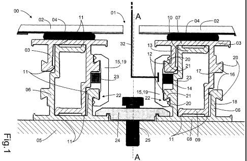
FIGURE 1 shows a detail from a photovoltaic plant 00 according to the
invention
in cross section in the region of a spacer gap 01 between two frameless
rectangular solar modules 02 (shown cut away from the side), which are
arranged in a regular matrix, so that a harmonic undisturbed appearance of the
photovoltaic plant results. A module rail 03 is in each case arranged on the
underside in the edge regions of the solar modules 02 which face one another.
In the exemplary embodiment shown, the module rails 03 are adhesively
bonded to the solar modules 02 by means of elastic glue joints 04. The solar
modules 02 are releasably but securely connected to a substrate 05 by means
of the module rails 03. In this case, the substrate 05 is a substructure,
SOL 2007/11/01 CA CA 02703074 2010-04-19
9
lightweight building board, sloping or flat roof or facade. Both horizontal
and
vertical installation of the solar modules 02 is possible.
The module rails 03 are in each case releasably coupled to substrate rails 06
for connection of the solar modules 02 to the substrate 05. Module rail 03 and
substrate rail 06 are arranged in positions which are rotated by 180 relative
to
one another and essentially have the same cross section. The transverse side
07 of the module rail 03 adjacent to the solar module 02 and the transverse
side 08 of the substrate rail 06 adjacent to the substrate 04, respectively,
is of
io L-shaped construction. The respectively opposite transverse sides 09, 10
have
a U-shaped course. To avoid static overdeterminations between the module
and substrate rails 03, 06 which lie on top of one another, the adjacent
transverse sides 07, 08 and the open ends of the opposite transverse sides
09,10 are in each case provided with brackets 11. Due to the construction of
the module and substrate rails 03, 06 and also due to their diametrically
rotated
arrangement with respect to one another, during the installation of the solar
modules 02, they can first be placed one inside the other, then displaced
laterally and finally pushed completely one inside the other. In the position
in
which they are pushed completely one inside the other, they - and therefore
the solar modules 02 - are secured against a lateral displacement. A pulling
apart of module rails 03 and substrate rails 06 - and therefore a lifting off
of the
solar modules 02 - is still possible, however.
For avoiding the pulling apart of module rails 03 and substrate rails 06,
these
have guide rails 12 running parallel to the solar module 02 or to the
substrate
05 on at least the longitudinal sides 13, 14 which face the spacer gap 01. By
means of the two guide rails 12 on the longitudinal sides 13, 14 of the module
and substrate rail 03, 06 which face the spacer gap 01, these are then
releasably connected to one another by means of at least one connecting
3o element 15. In this case, the spacer gap 01 between the adjacent solar
modules 02 has a width sufficient for operating the connecting element 15. In
SOL 2007/11/01 CA CA 02703074 2010-04-19
the selected exemplary embodiment, the module rail 03 and the substrate rail
06 have exactly the same profile, as a result of which, the production of the
rails, for example by means of extrusion and their procurement is
substantially
facilitated. The module rail 03 and substrate rail 06 therefore also have
guide
5 rails 16 on the longitudinal sides 17, 18 facing away from the spacer gap,
in
addition to the guide rails 12 on the longitudinal sides 13, 14 facing the
spacer
gap 01. These are not used to connect the module rail 03 and substrate rail 06
however in the exemplary embodiment shown, as they are located inaccessibly
underneath the solar module 02. For mutual guiding, the module rail 03 and
io substrate rail 06 likewise have brackets 11 on their facing longitudinal
sides 13,
18.
In the exemplary embodiment shown, the connecting element 15 is
constructed as a slider 19 which can be displaced on the guide rails 13, 14.
To
is this end, the guide rails 13, 14 have oblique undercuts 20. The guide rails
13,
14 connected to one another by means of the connecting element 15 have
opposite oblique undercuts 20. Together with oblique undercuts 21 on the
displaceable slider 19, the oblique undercuts 20 on the module and substrate
rails 03, 06 form a dovetail guide 22. In the case of the displaceable slider
19
as a connecting element 15, the spacer gap 01 between the solar modules 02
for displacing the slider 19 can be very narrow. It must only be possible for
a
single displacement tool 32 of a type similar to a screw driver to be able to
engage through it (shown dashed in FIGURE 1). To secure the displaceable
slider 19 with respect to the substrate rail 06, a spring shackle 23 is
provided
on the slider 19 in the exemplary embodiment selected. In the lower region of
the mutually opposite substrate rails 06 of adjacent solar modules 02, a
fixing
rail 24 which engages over the substrate rails 06, which fixing rail can be
screwed to the substrate 05 by means of a screw connection 25. As a result,
the secure composite linkage of the solar modules 02 to the substrate 05 is
closed, and it is reliably ensured that the solar modules 02 cannot lift off
from
the substrate 05 by means of wind force.
SOL 2007/11/01 CA CA 02703074 2010-04-19
11
FIGURE 2 shows a cut away sectional illustration in the spacer gap 01 with a
view of the right half of the photovoltaic plant 00 (section AA according to
FIGURE 1). The solar module 02, the glue joint 04, the module rail 03, the
slider
19, the substrate rail 06, the fixing rail 24 and the screw connection 25 for
the
screw connection in the substrate 05 can be recognised. The width of the
slider
19 and its positioning in the edge region 26 of the solar module 02 can be
seen. In the exemplary embodiment selected, the rails 03, 06 and the slider 19
laterally project slightly beyond the solar module 02, without impairing the
1o homogeneous overall impression of the frameless solar modules 02 in the
plan
view, however.
FIGURE 3 shows a perspective view of the slider 19. The oblique undercuts 21
for forming the dovetail guide 22 and the spring shackle 23 for bracing the
slider 19 against the substrate rail 06 can be seen (cf. FIGURE 1) .
FIGURE 4 shows an alternative embodiment of a slider 27 on the right with a
screw connection 28 for bracing the slider 27 with respect to the module rail
03.
A double slider 29 for the simultaneous connection of the rail systems of two
solar modules 02 is shown on the left. The double slider 29 consists of two
identical guide pieces 30, which are connected to one another by means of a
screw connection 31. Both alternative sliders 27, 29 would be to be arranged
in
the region of the spacer gap 01.
REFERENCE LIST
00 Photovoltaic plant
01 Spacer gap
02 Frameless rectangular solar module
SOL 2007/11/01 CA CA 02703074 2010-04-19
12
03 Module rail
04 Glue joint
05 Substrate
06 Substrate rail
07 Transverse side of 03 adjacent to 02
08 Transverse side of 06 adjacent to 05
09 Transverse side of 03 opposite 07
Transverse side of 06 opposite 08
11 Bracket
l0 12 Guide rail facing 01
13 Longitudinal side of 03 facing 01
14 Longitudinal side of 06 facing 01
Connecting element
16 Guide rail facing away from 01
15 17 Longitudinal side of 03 facing away from 01
18 Longitudinal side of 06 facing away from 01
19 Displaceable slider
Oblique undercut on 12, 16
21 Oblique undercut on 19
20 22 Dovetail guide
23 Spring shackle
24 Fixing rail
Screw connection of 24
26 Edge region of 02
25 27 Slider (alternative embodiment)
28 Screw connection of 27
29 Double slider
Guide piece
31 Screw connection of 29
30 32 Displacement tool