Note: Descriptions are shown in the official language in which they were submitted.
CA 02703382 2010-05-10
09-289-2
HYDROCONVERSION PROCESS FOR HEAVY AND EXTRA HEAVY OILS AND
RESIDUALS
Background of the Invention
[0001] The invention relates to a catalytic process for
hydroconversion and, more particularly, to a process and
additive for such a process.
[0002] Hydroconversion processes in general are known, and
one example of such a process is that disclosed in co-pending
and commonly owned US patent application 12/113,305, filed May
1, 2008. In the process disclosed therein, catalysts are
provided in aqueous or other solutions, one or more emulsions of
the catalyst (aqueous solution) in oil are prepared in advance
and the emulsions are then mixed with the feedstock, with the
mixture being exposed to hydroconversion conditions.
[0003] The disclosed process is generally effective at the
desired conversion. It is noted, however, that the catalysts
used are potentially expensive. It would be beneficial to find
a way to recover this catalyst for re-use.
[0004] In addition, foaming and the like in hydroconversion
reactors can create numerous undesirable consequences, and it
would be desirable to provide a solution to such problems.
[0005] Hydroconversion processes in general for heavy
residues, with high metal, sulfur and asphaltene contents,
cannot reach high conversions (more than 80wto) without recycle
and high catalyst concentration.
Summary of the Invention
[0006] In accordance with the invention, a catalytic
hydroconversion process and additive are provided wherein the
1
DOCSMTL: 3876183\1
CA 02703382 2010-05-10
09-289-2
additive scavenges catalyst metals and also metals from the
feedstock and concentrates them in a heavy stream or unconverted
residue material which exits the process reactor, and this heavy
stream can be treated to recover the metals. The stream can be
processed into flake-like materials. These flakes can then be
further processed to recover the catalyst metals and other
metals in the flakes which originated in the feedstock. This
advantageously allows the metals to be used again in the
process, or to be otherwise advantageously disposed of.
[0007] According to the invention, a hydroconversion process
is provided which comprises the steps of feeding a heavy
feedstock containing vanadium and/or nickel, a catalyst emulsion
containing at least on group 8-10 metal and at least one group 6
metal, hydrogen and an organic additive to a hydroconversion
zone under hydroconversion conditions to produce an upgraded
hydrocarbon product and a solid carbonaceous material containing
said group 8-10 metal, said group 6 metal, and said vanadium.
[0008] Further, the additive can be use to control and
improve the overall fluid-dynamics in the reactor. This is due
to an anti-foaming effect created by use of the additive in the
reactor, and such foam control can provide better temperature
control in the process as well.
[0009] The additive is preferably an organic additive, and
may preferably be selected from the group consisting of coke,
carbon blacks, activated coke, soot and combinations thereof.
Preferred sources of the coke include but are not limited to
coke from hard coals, and coke produced from hydrogenation or
carbon rejection of virgin residues and the like.
[0010] The additive can advantageously be used in a process
for liquid phase hydroconversion of feedstocks such as heavy
2
DOCSMTL: 3876183\1
CA 02703382 2010-05-10
09-289-2
fractions having an initial boiling point around 500 C, one
typical example of which is a vacuum residue.
[0011] In the process, the feedstock is contacted in the
reaction zone with hydrogen, one or more ultradispersed
catalysts, a sulfur agent and the organic additive. While the
present additive would be suitable in other applications, one
preferred process is carried out in an upflow co-current three-
phase bubble column reactor. In this setting, the organic
additive can be introduced to the process in an amount between
about 0.5 and about 5.0 wt% with respect to the feedstock, and
preferably having a particle size of between about 0.1 and about
2,000 pm.
[0012] Carrying out the process as described herein using the
organic additive of the invention, the organic additive
scavenges catalyst metals from the process, for example
including nickel and molybdenum catalyst metals, and also
scavenges metals from the feedstock, one typical example of
which is vanadium. Thus, the product of the process includes a
significantly upgraded hydrocarbon product, and unconverted
residues containing the metals. These unconverted residues can
be processed into solids, for example into flake-like materials,
containing heavy hydrocarbon, the organic additive, and
concentrated catalyst and feedstock metals. These flakes are a
valuable source of metals for recovery as discussed above.
Brief Description of the Drawings
[0013] A detailed description of preferred embodiments of the
invention follows, with reference to the attached drawing,
wherein:
3
DOCSMTL: 3876183\1
CA 02703382 2010-05-10
09-289-2
[0014] Figure 1 schematically illustrates a process according
to the invention; and
[0015] Figure 2 shows a more detailed schematic illustration
of a system for carrying out the process in accordance with the
present invention.
Detailed Description
[0016] The invention relates to a process and additive for
catalytic hydroconversion of a heavy feedstock. The additive
acts as a scavenger of catalyst and feedstock metals, and
concentrates them in a residual phase for later extraction.
Further, the additive serves as a foam controlling agent, and
can be used to improve overall process conditions.
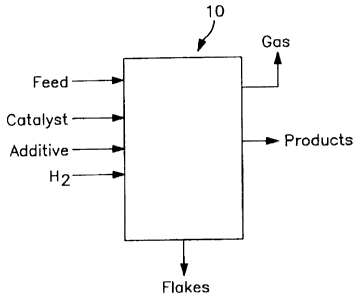
[0017] Figure 1 shows a hydroconversion unit 10 to which are
fed the feedstock, catalyst preferably in an ultradispersed
form, an organic additive, sulfur agent and hydrogen. Within
unit 10, conversion of the feedstock occurs, and the outflows
from unit 10 include a product stream including an upgraded
hydrocarbon phase which can be separated into liquid and gas
phases for further treatment and/or feeding to a gas recovery
unit as desired, and residue which can be solidified into flakes
of the spent organic additive material with scavenged catalyst
and feedstock metals.
[0018] The feedstock can be any heavy hydrocarbon, and one
particularly good feedstock is vacuum residue which can have
properties as set forth in Table 1 below:
4
DOCSMTL: 3876183\1
CA 02703382 2010-05-10
09-289-2
Table 1
Properties Unit
Distillation LVo
ASTM D1160
IBP OF 600-900
Viscosity@210 F cst < 80000
API - 1-7
Sulfur wt'-0 3 - 8
Nitrogen wt*-. < 2
Asphaltenes wt'-. 15-30
Conradson Carbon wt'-. 15-30
Metal (V+Ni) wtppm 200-2000
[0019] Alternative feeds include but are not limited to feeds
derived from tar sands and/or bitumen.
[0020] For a vacuum residue (VR) feedstock, this can come
from a vacuum distillation unit (VDU) for example, or any other
suitable source. Other similar feeds can be used, especially if
they are of a type that can be usefully upgraded through
hydroconversion and contain feedstock metals such as vanadium
and/or nickel.
[0021] As shows in Fig. 2, advantageously, the feedstock can
be fed directly to the reactors 25, 27 without any pretreatment
other than mixing with the desired emulsions and other reactant
streams.
[0022] As indicated above, the additive is preferably an
organic additive such as coke, carbon black, activated coke,
5
DOCSMTL: 3876183\1
CA 02703382 2010-05-10
09-289-2
soot, and combinations thereof. These materials can be obtained
from any of numerous sources, and are readily available at very
low cost. The organic additive can preferably have a particle
size of between about 0.1 and about 2,000 pm.
[0023] The catalysts used are preferably a metal phase as
disclosed in co-pending US 12/113,305. The metal phase
advantageously is provided as one metal selected from groups 8,
9 or 10 of the periodic table of elements, and another metal
selected from group 6 of the periodic table of elements. These
metals can also be referred to as group VIA and VIIIA metals, or
group VIB and group VIIIB metals under earlier versions of the
periodic table.
[0024] The metals of each class are advantageously prepared
into different emulsions, and these emulsions are useful as
feed, separate or together, to a reaction zone with a feedstock
where the increased temperature serves to decompose the
emulsions and create a catalyst phase which is dispersed through
the feedstock as desired. While these metals can be provided in
a single emulsion or in different emulsions, both well within
the scope of the present invention, it is particularly preferred
to provide them in separate or different emulsions.
[0025] The group 8-10 metal(s) can advantageously be nickel,
cobalt, iron and combinations thereof, while the group 6 metal
can advantageously be molybdenum, tungsten and combinations
thereof. One particularly preferred combination of metals is
nickel and molybdenum.
[0026] The method for preparing this emulsion is discussed
below. The end result can be a single water-oil emulsion where
the water droplets contain both the group 6 and group 8, 9 or 10
metals. Alternatively, two separate emulsions can be prepared
6
DOCSMTL: 3876183\1
CA 02703382 2010-05-10
09-289-2
and fed to a hydroconversion process, wherein each emulsion
contains one of the metallic phases. Either of these systems is
considered to fall within the broad scope of the present
invention.
[0027] It is also within the scope of the invention to
utilize more than the two mentioned metals. For example, two or
more metals from group 8, 9 or 10 can be included in the
catalyst phases of the emulsions.
[0028] In further accordance with the invention, it has been
found that the catalyst phase is particularly effective when the
group 6 metal is provided in the form of a sulfide metal salt.
When decomposed during the hydroconversion process, these
sulfides form sulfide metal particles which are advantageous in
the subsequent hydroconversion processes.
[0029] The catalyst emulsion(s) and heavy feedstock can be
fed to the reactors preferably in amounts sufficient to provide
a ratio of catalyst metals to heavy feedstock, by weight, of
between about 50 and about 1,000 wtppm.
[0030] Hydrogen can be fed to the process from any suitable
source.
[0031] The reaction conditions can be as set forth in Table 2
below:
Table 2
Reactor Pressure 130-210 barg
Reactor Temperature 430-470 C
Conversion Rate 80% or more
[0032] Typical yield from a specified feedstock is set forth
in Table 3 below:
7
DOCSMTL: 3876183\1
CA 02703382 2010-05-10
09-289-2
Table 3
Feed Stock Weight
Vacuum Residue 100
Catalyst
Emulsions + 8 - 10
Coke Additive
Flushing Oil 2.6 - 3.6
(HGO)
Hydrogen 1.8- 3
Feed Total 112.4-116.6
Products
Cl - C4 7 - 9
H2O 1 - 2
H2S + NH3 3.4-4.0
Naphtha 16-20
Middle 28-34
Distillates
VGO 40-45
Total Products 95.4 - 114
(excl. Flakes)
Unconverted 17-9
Residue or
Flakes
[00331 In a slurry feed process according to the invention,
the unit 10 receives a vacuum residue (VR). The additive
8
DOCSMTL: 3876183\1
CA 02703382 2010-05-10
09-289-2
particles can be added to the VR and agitated. The agitated
slurry is preferably pumped up to an elevated pressure,
preferably over 200 barg, by high-pressure slurry pumps. The
slurry is also heated to an elevated temperature, preferably
over 400 C. Upstream, catalyst emulsions, sulfur agent and
hydrogen are injected unto the slurry feed. After a slurry
furnace for heating the slurry, more hydrogen can be added if
needed.
[0034] The total mixture of VR, organic additive, catalyst
emulsions, sulfur agent and hydrogen are introduced into the
reactor and deeply hydroconverted into the desired lighter
materials. Most of the hydroconverted materials are separated
as vapor in a High Pressure High Temperature separator, and the
vapor can be sent to a later unit for hydrotreating and further
hydrocracking as needed. The vacuum gas oil (VGO) produced can
also be fed to a later reactor, as desired.
[0035] In the meantime, the bottom product of the separator,
in the form of a heavy slurry liquid, can be sent to a vacuum
distillation unit to recover, under vacuum, any remaining
lighter materials, and the final remaining bottom residue which
is the unconverted residue could be sent to different type of
processes where it can be converted into a solid material. One
of these units could be a flaker unit wherein the bottom residue
can be solidified. These resulting flakes can advantageously
have the following composition:
9
DOCSMTL: 3876183\1
CA 02703382 2010-05-10
09-289-2
Table 4
Physical state and appearance Solid brittle
API -5 - (-14.4)
Color Brilliant Black
Volatility Negligible at room
temperature
Boiling Point Greater than 500 C
Density at 15 C (kg/m3) 900 - 1350
Toluene Insoluble wt-. 15 - 40
Asphaltenes (IP-143) wt% 30 - 50
preferably 30 - 40
Heptane Insoluble (wt% ) 28 - 50
Carbon Residue (Micron 22 - 55
Method) wt%
Molybdenum wtppm 1500 - 5000
Vanadium wtppm 1400 - 6500
Nickel wtppm 50 - 3000
Carbon Content wt% 85 - 93
Hydrogen Content wt% 5 - 9
Ratio Carbon/Hydrogen 10 - 17
Total Nitrogen wt% 1. - 2.5
Sulfur wt% 2.2 - 2.7
VGO (%) 6 - 14
Ash wt% 0.2 - 2.0
DOCSMTL: 3876183\1
CA 02703382 2010-05-10
09-289-2
Volatile Matter wto: 61.4 60 - 80
Heating Value BTU/Lb 15700 - 16500
Moisture wt% : 0 - 8.00
Hardness index (HGI) 50 - 68
Softening Point C : 110 - 175
Kinematic Viscosity at 275 F 13,000 - 15,500
cSt
Flash Point C 300 - 310
Pour Point C 127
Simulated distillation (D- % OFF(wt%) T ( C)
7169)
IBP 442.9
1 445.6
490.7
510.9
527.0
541.9
557.7
574.9
618.9
668.5
58 715.0
[0036] These flakes, containing remaining organic additive
and also the catalyst metals and metal from the feedstock which
11
DOCSMTL: 3876183\1
CA 02703382 2010-05-10
09-289-2
is scavenged by the additive according to the process of the
present invention, can themselves be provided to consumers as a
source of useful metals, or can be used as fuel, or can be
treated for extraction of the metals for re-use as process
catalyst and the like. The metals can be removed from the
flakes for example using combustion or thermal oxidation to
convert the flakes into ash which concentrates the metals and
removes any remaining hydrocarbons, or by using a
desolidification procedure with solvent to isolate the solid
containing the metals.
[0037] Of course, the metals to be recovered include not only
the catalyst metals used in the process, but also certain metals
such as vanadium which are native to the feedstock. One
preferred way to recover all these metals is in a staged process
wherein each stage conducts the separation of metal and uses
carbon filtration units that allow the recovery of very fine
particles.
[0038] Figure 2 shows a more detailed system for carrying out
the process of the present invention. As shown, the system has
a hydroconversion section having one or more reactors, in this
case two reactors 25 and 27, which will be discussed below.
[0039] The hydroconversion is carried out in reactors 25, 27.
These reactors are connected in series, for example by line 26,
and are fed with a combination of feedstock and various other
reaction ingredients.
[0040] As shown to the left of reactor 25, the feed itself
which is to be processed, shown as VR Feed or vacuum residue
feed, is advantageously mixed with a coke additive from an
additive preparation unit 1 through line 2 into mixer 3, and the
resulting combination of feedstock and coke additive is passed
12
DOCSMTL: 3876183\1
CA 02703382 2010-05-10
09-289-2
through line 4 to a slurry pump 5 which serves to further pump
the slurry of feedstock and coke additive through line 18 toward
a feedstock heater 21 as shown. In addition, one or more
catalyst emulsions, in this example two catalyst emulsions, are
prepared as discussed above in units 10 and 14, fed through
lines 11 and 15 to pumps 12 and 16, respectively, and then
pumped through lines 13 and 17 into line 18 to combine with the
feedstock/additive mixture, preferably at one or more points
between pump 5 and heater 21.
[0041] Catalyst emulsions are shown in this schematic as
being fed to the line which already contains the vacuum residue
feedstock and coke additive, and the catalyst emulsions can be
prepared at any catalyst emulsion preparation unit upstream of
this line.
[0042] During startup of the process, a sulfur agent can be
drawn from tank 6 through line 7 to pump 8 and fed through line
9 to be mixed with the other reactants in line 18. This forms
the activated species as desired. The sulfur agent can
preferably be recycled from H2S contained in the gas recycled
from the products, and this recycled sulfur gas can be fed
through various separating equipment to be discussed below, to
line 50, and back to reactor 25 as desired.
[0043] Hydrogen is also fed to the reactant stream to carry
out hydroconversion as desired. Figure 2 shows Fresh Hydrogen
being fed to the process through line 51 to line 52 where it is
joined by recycle hydrogen and fed to preheaters 19, 22, and
then lines 20, 23. The portion fed through preheater 19 and
line 20, preferably 30-90owt of the gas to be used in the
process, is heated in preheater 19 to a temperature preferably
13
DOCSMTL: 3876183\1
CA 02703382 2010-05-10
09-289-2
between about 200 C and about 600 C, and then mixed with the
other reaction feeds prior to heater 21, and this combined
mixture is fed through line 24 to reactor 25.
[0044] The second portion of the hydrogen, fed through line
23, is fed after the heater 21.
[0045] The combination of additive, feedstock, catalyst
emulsions and hydrogen is then passed through heater 21 to raise
the temperature of the fluids as desired, and then such fluids
are passed to reactors 25 and 27, where they are exposed to
hydroconversion conditions. The product stream from reactors
25, 27 is fed through line 28 to an HPHT (High Pressure High
Temperature) separator 29, where the light products are separated
from the heavy product, which contains the unconverted liquid,
the organic additive and the used catalyst. The liquid and heavy
phase separated from HPHT separator 29 is passed to a recovery
metal section 32 which could include a vacuum flash tower. In
this stage materials can then be fed to a solidification unit.
[0046] Hydrogen is also shown being added to the reactant
stream, in this instance in two locations. One location of
hydrogen addition is just prior to the feed heater 21, and the
other point of introduction of additional hydrogen is after the
feed heater 21. All the hydrogen feed is provided from recycled
hydrogen and make-up hydrogen as shown in Figure 2. As shown,
at least a portion of the hydrogen goes to the preheater 19
prior to being fed to the heater 24 and the other portion goes
to the preheater 22.
[0047] Reactors 25, 27 can advantageously be tubular
reactors, vertically spaced, with or without internals,
preferably without, where the liquid, solid and gas go upstream.
This is the area where conversion takes place, under average
14
DOCSMTL: 3876183\1
CA 02703382 2010-05-10
09-289-2
temperatures between 250 and 500 C, preferably between 400 and
490 C, at a hydrogen partial pressure between 50 and 300 bar,
and a gas/liquid ratio of between 100 and 15,000 Nm3/T.
[0048] It should be noted that in separators 29, 39, products
from line 28 exiting reactor 27 are separated, and light
products are separated from the heavy products. The heavy
products contain the non-converted liquid, the organic additive
and the used catalyst.
[0049] The heavy product is fed through line 31 to the metal
recovery section 32.In this section, HHGO (heavy hydroconverted
gasoil) is separated from the non-converted residue and organic
additive using a vacuum residue tower or the like. The HHGO can
be used in emulsion preparation, and the mixture of residue,
non-converted liquid and organic additive can be cooled and sold
as flakes. The metals can be extracted from the non-converted
liquid and the organic additive, or could be extracted from the
flakes.
[0050] The hot separator bottoms can have various uses,
several non-limiting examples of which will be discussed below.
[0051] For the metal extraction process, the feed selected
(flakes or bottom of vacuum distillation tower) is converted
into a form from which the metals can be recovered. The
recovery of the metals should be carried out in a two-stage
process. The first stage comprises a pyrolysis or thermal
oxidation either at low or high temperatures to remove the tars,
and the second stage comprises an acid or basic lixiviation.
[0052] The light products in line 30 from separator 29 are
mixed with wash water from tank 33, which water is fed through
line 34 and pump 35 to line 36 and into line 30. This mixture
DOCSMTL: 3876183\1
CA 02703382 2010-05-10
09-289-2
is cooled in heat exchanger 37 and these products are then sent
through line 38 to the second separator 39.
[0053] There are three streams 40, 41, 42 coming out from the
second separator 39. The first stream 40 comprises the sour
water, the second stream 41 is the process gas (C1-4, H2S, NH3,
H2, C5+) that goes to recycle line 45 and to the purge section
46, and the third stream 42 contains the liquid products.
[0054] The recycle gas 45 passes through a filter 47 to
remove impurities and then is compressed 49 and mixed with fresh
hydrogen 51. This mixture goes in a proportion, between 10/90
to 50/50 (fresh hydrogen/recycle gas), to the gas preheaters
(19, 22).
[0055] It should also be noted that fresh hydrogen can be fed
through line 53 to lines 54, 55 and 56 to supply hydrogen gas at
these various points of need in reactors 25, 27 and separator
29.
EXAMPLE 1
[0056] Following the scheme represented in Fig. 2, the
following experiment was conducted.
[0057] A heavy feedstock comprised by a conventional vacuum
residue (VR) of Venezuelan oil, Petrozuata, was fed into a
reactor with a total capacity of 10 BPD. Said reactor was a
slurry bubble column reactor without any internals, with a
temperature control based on a preheater system and cool gas
injection. This reactor has a length of 1.6 m and a diameter of
12 cm.
[0058] This reactor was operated at 0.52 T/m3h (spatial
velocity) at a total pressure of 170 barg, a gas to liquid ratio
(H2/liquid) of 32990 scf/bbl, a gas velocity of 5.98 cm/s. An
16
DOCSMTL: 3876183\1
CA 02703382 2010-05-10
09-289-2
organic additive was added to the feedstock in a concentration
of 1.5 wt% and with a particle size ranging 200-300 pm. At these
conditions, an ultradispersed catalyst was injected to the
process to obtain 92 wtppm of nickel and 350 wtppm of molybdenum
sulfide inside the reactor.
[0059] The average temperature inside the reactor was 458 C.
The average residue conversion reached at these conditions was
94.3 wt% and the asphaltene conversion was 89.2 wt%.
[0060] The residue 500 C+ (R) conversion is estimated as
follows:
[0061] X500 C+ = Rin - Rout X100
Rin
[0062] The process described in this example was carried out
in a continuous operation for 21 days. Three serially connected
vertical slurry reactors were used during this test.
[0063] This example is summarized in the following table:
Feedstock characteristics
API density (60 F) 2.7
Residue 500 C+ (wt%) 90.95
Asphaltenes (IP-143) (wt%) 18.7
Metal content (V + Ni) (wtppm) 959
Sulfur (wt%) 3.10
Process variables
WSHV (T/m3h) 0.52
Feedrate (kg/h) 30
Total pressure (barg) 170
Reactor average temperature ( C) 458
Gas / Liquid ratio (scf/bbl) 32990
Gas superficial velocity (inlet first reactor) (cm/s) 5.98
Particle size (pm) 200-300
17
DOCSMTL: 3876183\1
CA 02703382 2010-05-10
09-289-2
Organic additive concentration (wt%) 1.5
Nickel catalyst concentration (wtppm) 92
Molybdenum catalyst concentration (wtppm) 350
Conversions
X500'C+ (wt %) 94.3
Xasphaltene (wt %) 89.2
Xmicrocarbon (wt %) 86.5
Xasphaltene / X500 C+ 0.9
Other Parameters
HDS (wt%) 69.7
HDN (wt%) 15.7
HDO (wt%) 35.0
HDNi (wt%) 98.4
HDV (wt%) 99.7
HDMo (wt%) 99.6
Products
Naptha (IBP-200 C)(wt%) 18.2
Middle distillates (200-343 C)(wt%) 31.6
VGO (343-500 C) (wt%) 33.6
Liquid products (wt%) 83.4
C1-C4 (wt%) 7.3
EXAMPLE 2
[0064] Following the scheme represented in Fig. 2, the
following experimentation was effected.
[0065] The test was carried out using a sample of vacuum
residue (VR) of Canadian oil, prepared from Athabasca crude.
[0066] This VR was fed into a pilot plant with a total
capacity of 10 BPD, with the same slurry bubble column reactor
18
DOCSMTL: 3876183\1
CA 02703382 2010-05-10
09-289-2
without any internals, as used in example 1, with a temperature
control based on a preheater system and cool gas injection.
[0067] For this test the reactor was operated at two
different spatial velocities of 0.42 and 0.73 T/m3h. Three
serially connected vertical slurry reactors were used during
this test. The plant was in continuous operation during 20 days.
[0068] At 0.42 T/m3h conditions were: total pressure of 169
barg, gas to liquid ratio (H2/liquid) of 34098 scf/bbl, gas
velocity of 7.48 cm/s, an organic additive concentration of 1.5
wto with a particle size ranging 200-300 pm, with an injection
of an ultradispersed catalyst to reach 92 wtppm of nickel and
350 wtppm of molybdenum inside the reactor. These conditions
were maintained for 11 days.
[0069] The average temperature inside the reactor was 453 C.
The average residue conversion reached at these conditions was
91.9 wt% and the asphaltene conversion was 93.6 wt%.
[0070] The results for these conditions are summarized in the
following table:
Feedstock characteristics
API density (60 F) 2.04
Residue 500 C+ (wt%) 97.60
Asphaltenes (insolubles in heptane) (wt%) 21.63
Metal content (V + Ni) (wtppm) 462
Sulfur (wt%) 6.56
Process variables
WSHV (T/m3h) 0.42
Feedrate (kg/h) 24
19
DOCSMTL: 3876183\1
CA 02703382 2010-05-10
09-289-2
Total pressure (barg) 169
Reactor average temperature ( C) 453
Gas / Liquid ratio (scf/bbl) 34098
Gas superficial velocity (inlet first reactor) (cm/s) 7.48
Particle size (pm) 200-300
Organic additive concentration (wt%) 1.5
Nickel catalyst concentration (wtppm) 92
Molybdenum catalyst concentration (wtppm) 350
Conversions
X500-c+ (wt%) 91.92
Xasphaltene (wt%) 93.6
Xmicrocarbon (wt %) 8 9 . 3 6
Xasphaltene / X500 C+ 1. 0
Other Parameters
HDS (wt%) 77.1
HDN (wt%) 7.9
HDO (wt%) 40.6
HDNi (wt%) 99.3
HDV (wt%) 99.9
HDMo (wt%) 100.0
[0071] At 0.73 T/m3h conditions were: total pressure of 169
barg, gas to liquid ratio (H2/liquid) of 19818 scf/bbl, gas
velocity of 7.57 cm/s, an organic additive concentration of 1.5
wt% with a particle size ranging 200-300 pm, with an injection
of an ultradispersed catalyst to reach 92 wtppm of nickel and
350 wtppm of molybdenum inside the reactor.
[0072] The average temperature inside the reactor was 462 C.
The average residue conversion reached at these conditions was
DOCSMTL: 3876183\1
CA 02703382 2010-05-10
09-289-2
91.2 wt-06 and the asphaltene conversion was 83.7 wt%. This
conditions was maintained for 6 days.
[0073] The results for these conditions is summarized in the
following table:
Feedstock characteristics
API density (60 F) 2.04
Residue 500 C+ (wt%) 97.60
Asphaltenes (insolubles in heptane) (wt%) 21.63
Metal content (V + Ni) (wtppm) 462
Sulfur (wt%) 6.56
Process variables
WSHV (T/m3h) 0.73
Feedrate (kg/h) 42
Total pressure (barg) 169
Reactor average temperature ( C) 462
Gas / Liquid ratio (scf/bbl) 19818
Gas superficial velocity (inlet first reactor) (cm/s) 7.57
Particle size (pm) 200-300
Organic additive concentration (wt%) 1.5
Nickel catalyst concentration (wtppm) 92
Molybdenum catalyst concentration (wtppm) 350
Conversions
X500-c+ (wt%) 91.21
Xasphaltene (wt %) 8 3 . 7 2
Xmicrocarbon (wt % ) 84.30
Xasphaltene / X500 C+ 0.9
Other Parameters
21
DOCSMTL: 3876183\1
CA 02703382 2010-05-10
09-289-2
HDS (wto) 75.01
HDN (wt%) 11.32
HDO (wt%) 41.83
HDNi (wt%) 98.87
HDV (wt%) 99.84
HDMo (wt%) 100.0
EXAMPLE 3
[0074] Following the scheme represented in Fig. 2, the
following experimentation was effected.
[0075] This third test was carried out using a mixture of
vacuum residue (VR) of Venezuelan oils, comprising Merey, Santa
Barbara, Anaco Wax and Mesa.
[0076] This VR was fed into a pilot plant with a total
capacity of 10 BPD, with the same slurry bubble column reactor
without any internals of example 1, with a temperature control
based on a preheater system and cool gas injection.
[0077] For this test the reactor was operated at two
different spatial velocities of 0.4 and 0.5 T/m3h, changing the
catalyst and the solid concentration. Three serially connected
vertical slurry reactors were used during this test. The plant
was in continuous operation for 39 days.
[0078] At 0.4 T/m3h spatial velocity, solids, catalysts and
sulfur ammonium concentrations were changed, in the following
table the results are summarized:
Feedstock characteristics
API density (60 F) 5.1
Residue 500 C+ (wt%) 94.83
22
DOCSMTL: 3876183\1
CA 02703382 2010-05-10
09-289-2
Asphaltenes (IP-143) (wt%) 16
Metal content (V + Ni) (wtppm) 578
Sulfur (wt%) 3.2
Process variables
WSHV (T/m3h) 0.4
Feedrate (kg/h) 24
Total pressure (barg) 169
Reactor average temperature ( C) 451 451 453 453 452
Gas / Liquid ratio (scf/bbl) 29152
Gas superficial velocity (inlet first
5.82
reactor) (cm/ s )
Particle size (pm) 212-850
Sulfur ammonium concentration (wt%) 0.2 0.2 0.2 0.2 4.47
Organic additive concentration (wt%) 1.5 2 2 2 2
Nickel catalyst concentration (wtppm) 100 100 118 132 132
Molybdenum catalyst concentration
400 400 450 500 500
(wtppm)
Conversions
X500'C+ (wt%) 82.8 81.8 83.9 85.2 85.4
Xasphaltene (wt%) 80.4 74.9 75.4 75.7 76.1
Xmicrocarbon (wt%) 74.7 80.8 79.2 82.9 83.7
Xasphaltene / X500oC+ 1.0 0.9 0.9 0.9 0.9
Other Parameters
HDS (wt%) 63.4
HDN (wt%) 40.7
HDO (wt%) 51.5
[0079] The operation conditions and the results at 0.5 T/m3h
spatial velocity, are presented in the following table:
23
DOCSMTL: 3876183\1
CA 02703382 2010-05-10
09-289-2
Feedstock characteristics
API density (60 F) 5.1
Residue 500 C+ (wt%) 94.83
Asphaltenes (IP-143) (wt%) 16
Metal content (V + Ni) (wtppm) 578
Sulfur (wt%) 3.2
Process variables
WSHV (T/m3h) 0.5
Feedrate (kg/h) 30
Total pressure (barg) 169
Reactor average temperature ( C) 456
Gas / Liquid ratio (scf/bbl) 29152
Gas superficial velocity (inlet first reactor) (cm/s) -
Particle size (pm) 212-850
Organic additive concentration (wt%) 1.5
Nickel catalyst concentration (wtppm) 100
Molybdenum catalyst concentration (wtppm) 400
Conversions
X500'C+ (wt %) 82.9
Xasphaltene (wt %) 79.6
Xmicrocarbon (wt % ) 72.4
Xasphaltene / X500 C+ 1.0
EXAMPLE 4
[0080] Following the scheme represented in Fig. 2, the
following experiment was conducted.
[0081] This example was carried out using a vacuum residue
(VR) of Venezuelan oil, Merey/Mesa.
24
DOCSMTL: 3876183\1
CA 02703382 2010-05-10
09-289-2
[0082] This VR was fed into a pilot plant with a total
capacity of 10 BPD, with the same slurry bubble column reactor
without any internals as in example 1, with a temperature
control based on a preheater system and cool gas injection.
[0083] For this test the reactor was operated at 0.4 T/m3h
(spatial velocity), using three serially connected vertical
slurry reactors.
[0084] The reactor was operated at a total pressure of 169
barg, a gas to liquid ratio (H2/liquid) of 40738 scf/bbl, a gas
velocity of 6.4 cm/s.
[0085] An organic additive was added to the feedstock in a
concentration of 1.5 wt% and with a particle size ranging 212-
850 pm. At these conditions an ultradispersed catalyst was
injected to the process to obtain 132 wtppm of nickel and 500
wtppm of molybdenum inside the reactor.
[0086] The average temperature inside the reactor was
452.10C. The average residue conversion reached at these
conditions was 80.9 wt% and the asphaltene conversion was 76.5
wt%. The plant was in continuous operation for 21 days.
[0087] This results are summarized in the following table:
DOCSMTL: 3876183\1
CA 02703382 2010-05-10
09-289-2
Feedstock characteristics
API density (60 F) 5.0
Residue 500 C+ (wt%) 96.3
Asphaltenes (IP-143) (wt%) 19.3
Metal content (V + Ni) (wtppm) 536
Sulfur (wt%) 3.28
Process variables
WSHV (T/m3h) 0.4
Feedrate (kg/h) 24
Total pressure (barg) 170
Reactor average temperature ( C) 452.1
Gas / Liquid ratio (scf/bbl) 40738
Gas superficial velocity (inlet first reactor) (cm/s) 6.4
Particle size (pm) 212-850
Organic additive concentration (wt%) 1.5
Nickel catalyst concentration (wtppm) 132
Molybdenum catalyst concentration (wtppm) 500
Conversions
X500-c+ (wt%) 80.9
Xasphaltene (Wt%) 76.5
Xmicrocarbon (wt %) 75.0
Xasphaltene / X5000c 0. 9
Other Parameters
HDS (wt%) 47.4
HDN (wt%) 22.7
HDO (wt %) 14.3
26
DOCSMTL: 3876183\1
CA 02703382 2010-05-10
09-289-2
HDV (wt%) 98.4
HDNi (wt%) 98.6
Products
Naptha (IBP-2000C)(wt%) 13.5
Middle distillates (200-343 C)(wt%) 22.5
VGO (343-500 C) (wt%) 43.1
Liquid products (wt%) 79.1
C1-C4 (wt%) 5.4
[0088] The above examples demonstrate the excellent results
obtained using the process according to the invention.
[0089] The present disclosure is provided in terms of details
of a preferred embodiment. It should also be appreciated that
this specific embodiment is provided for illustrative purposes,
and that the embodiment described should not be construed in any
way to limit the scope of the present invention, which is
instead defined by the claims set forth below.
27
DOCSMTL: 3876183\1