Note: Descriptions are shown in the official language in which they were submitted.
CA 02703401 2010-05-11
= ,
CONSTRUCTION JOINTS AND RELATED CONNECTORS
Field of the Invention
100011 The present invention relates to the field of construction joints,
and more specifically
to a modular construction joint and method of assembly thereof
Background of the Invention
100021 Construction joints and connectors for connecting between two and
six orthogonal
structural members are widely known and used in the prior art. Prior art
connectors and joint
constructions have often included specially formed connectors occupying large
transport space,
and relatively complex field operations in either assembling the joints or
modifying the structural
members in the field prior to forming the joints. These operations can be time
consuming and
require a degree of expertise and workmanship at a construction site.
Furthermore, prior art
connectors are often visible between connected structural members and use of
any space between
the structural members is limited or hindered in some fashion.
100031 Various attempts at resolving some of the aforementioned
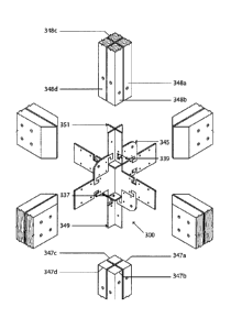
deficiencies have been
attempted, one of which is disclosed in United States Patent 4,863,305 to
Schold, wherein an
orthogonal construction joint is disclosed to interconnect two or more beams
and one or two
posts. As is evident from Figures 2 and 3 of Schold, the beams and posts
require significant
modification and complex shapes in order to work the Schold connector.
Furthermore, Schold
relies on angled bolts or screws to provide resistance to moment and torsion
loads and affix the
beams to the connector. Complex machining and modification of the beams as is
required by
Schold. Furthermore, the Schold connector is not readily adaptable to
different configurations
and more complex joint types as is often required in structural frame
constructions.
100041 Various other construction joints require significant tooling
costs in manufacturing
the connectors or rely on field workmanship of construction personnel to
ensure a proper joint is
formed. It is an object of this invention to partially or completely fulfill
one or more of the
above-mentioned needs.
1 84625-3 (YB)
LM - #113946v1
CA 02703401 2010-05-11
Summary of the Invention
100051 The invention in a preferred embodiment described herein comprises a
connector for
use in a construction joint including a first plate having respective first
and second ends, and a
first slit extending from the first end to a predetermined depth on the first
plate, and a second
plate having respective first and second ends, and a second slit extending
from the second end of
the second plate to a predetermined depth on the second plate. The first and
second plates
intersecting through the first and second slits such that the connector has a
cross-section that is,
at least in part, generally cruciform-shaped.
100061 According to one aspect of the preferred embodiment, the first plate
further includes a
bearing plate slit formed between an end of the first slit and the second end
of the first plate, and
extending generally perpendicular to the first slit; the bearing plate slit
adapted to receive a
bearing plate therein. The bearing plate is positioned such that the second
end of the second
plate abuts against the bearing plate.
100071 According to another embodiment of the invention, the first plate
further includes a
first projecting member extending from a first side of the first plate and a
second projecting
member extending form a second side of the first plate.
100081 According to another embodiment of the invention, the bearing plate
includes a slit
adapted to interact with the bearing plate slit on the first plate.
100091 According to a further embodiment of the invention, there is
provided a second
bearing plate. In this embodiment, the second plate further includes a second
bearing plate slit
formed between an end of the second slit and the first end of the second
plate, and extending
generally perpendicular to the second slit; the second bearing plate slit
receiving the second
bearing plate therein. The second bearing plate is positioned such that the
first end of the first
plate abuts against the second bearing plate.
100101 According to one aspect of the invention, an ear plate is provided
and functionally
attached to one of the first projecting member and the second projecting
member and a portion of
2 84625-3 (YB)
LM - #113946v1
CA 02703401 2010-05-11
the first plate proximate the first slit. Preferably, the bearing plate
includes a first bearing plate
portion and a second bearing plate portion; the first bearing plate slit
including two portions
extending in part from opposite ends of the first plate to receive therein the
first bearing plate
portion and the second bearing plate portion, respectively.
100111 According to another aspect of the invention, the first projecting
member further
includes one of a male or female flitch portion adapted to connect to an
adjacent and
complimentary flitch portion on a projecting member on an adjacent connector.
100121 According to another embodiment of the invention, there is provided
a method for
forming a construction joint including providing a first plate having
respective first and second
ends, and a first slit extending from the first end to a predetermined depth
on the first plate;
providing a second plate having respective first and second ends, and a second
slit extending
from the second end of the second plate to a predetermined depth on the second
plate; and
positioning the first and second plates such that the first and second slits
intersect, thereby
resulting in a cross-section that is, at least in part, generally cruciform-
shaped.
100131 According to one aspect of this embodiment, the first plate further
includes a bearing
plate slit formed between an end of the first slit and the second end of the
first plate, and
extending generally perpendicular to the first slit; and the method further
includes providing a
bearing plate and positioning the bearing plate to be received by the bearing
plate slit, wherein
the bearing plate is positioned such that the second end of the second plate
abuts against the
bearing plate.
100141 According to another aspect of this embodiment, the second plate
further includes a
second bearing plate slit formed between an end of the second slit and the
first end of the second
plate, and extending generally perpendicular to the second slit; the method
further including
providing a second bearing plate and positioning the second bearing plate to
be received by the
second bearing plate slit, wherein the second bearing plate is positioned such
that the first end of
the first plate abuts against the second bearing plate.
3 84625-3 (YB)
LM - #113946v1
CA 02703401 2010-05-11
100151 According to another embodiment of the invention, there is disclosed
a kit for
forming connectors for use in constructions joints including at least one
first plate having
respective first and second ends, and a first slit extending from said first
end to a predetermined
depth on the first plate, the first plate further including a bearing plate
slit formed between an end
of the first slit and the second end of said first plate, and extending
generally perpendicular to the
first slit. The kit further includes at least one second plate having
respective first and second
ends, and a second slit extending from the second end of the second plate to a
predetermined
depth on the second plate; and, at least one bearing plate having a bearing
plate slit. Numerous
other optional elements of the kit are also disclosed.
100161 Other advantages, features and characteristics of the present
invention, as well as
methods of operation and functions of the related elements of the structure,
and the combination
of parts and economies of manufacture, will become more apparent upon
consideration of the
following detailed description and the appended claims with reference to the
accompanying
drawings, the latter of which is briefly described hereinbelow.
Brief Description of the Drawings
100171 The invention will now be described in more detail, by way of
example only, with
reference to the accompanying drawings, in which like numbers refer to like
elements, wherein:
Figure 1 is a perspective view of a frame construction employing various
connectors and
joints according to the present invention;
Figure 2A is a top plan view of the various plates forming a connector
according to one
embodiment of the invention;
Figure 2B is a perspective view of the assembled connector of Figure 2A;
Figure 2C is an exploded view of the connector of Figure 2B;
Figure 3A is a top plan view of the various plates forming a connector
according to a
second embodiment of the invention;
4 84625-3 (YB)
LM - #113946v1
CA 02703401 2010-05-11
Figure 3B is a perspective view of the assembled connector of Figure 3A;
Figure 3c is an exploded view of the connector of Figure 3B;
Figure 4a is a top plan view of the various plates forming a connector
according to a third
embodiment of the invention;
Figure 4b is a perspective view of the assembled connector of Figure 4a;
Figure 4c is an exploded view of the connector of Figure 4b;
Figure 5a is a top plan view of the various plates forming a connector
according to a
fourth embodiment of the invention;
Figure 5b is a perspective view of the assembled connector of Figure 5a;
Figure Sc is an exploded view of the connector of Figure 5b;
Figure 6a is a top plan view of the various plates forming a connector
according to a fifth
embodiment of the invention;
Figure 6b is a perspective view of the assembled connector of Figure 6a;
Figure 6c is an exploded view of the connector of Figure 6b;
Figure 7a is a top plan view of the various plates forming a connector
according to a sixth
embodiment of the invention;
Figure 7b is a perspective view of the assembled connector of Figure 7a;
Figure 7c is an exploded view of the connector of Figure 7b;
Figure 8a is a top plan view of the various plates forming a connector
according to a
seventh embodiment of the invention;
84625-3 (YB)
LM - #113946v1
CA 02703401 2010-05-11
, .
Figure 8b is a perspective view of the assembled connector of Figure 8a;
Figure 8c is an exploded view of the connector of Figure 8b;
Figure 9a is a top plan view of the various plates forming a connector
according to an
eight embodiment of the invention;
Figure 9b is a perspective view of the assembled connector of Figure 9a;
Figure 9c is an exploded view of the connector of Figure 9b;
Figure 10a is a top plan view of the various plates forming a connector
according to a
ninth embodiment of the invention;
Figure 10b is a perspective view of the assembled connector of Figure 10a;
Figure 10c is an exploded view of the connector of Figure 10b;
Figure 11 a is a top plan view of the various plates forming a connector
according to a
tenth embodiment of the invention;
Figure llb is a perspective view of the assembled connector of Figure 11a;
Figure lie is an exploded view of the connector of Figure lib; and,
Figure 12 is a top plan view of a kit for forming connectors according to the
invention.
Detailed Description of the Preferred Embodiments
100181 Referring now to Figure 1, there is shown a representative
frame construction 10
within which the construction joints and connectors of the present invention
are preferably used.
It will be understood by those skilled in the art that while the present
invention is herein
described with reference to the representative frame construction, the
invention is not limited to
6 84625-3
(YB)
LM - #113946v1
CA 02703401 2010-05-11
use in such a frame construction. Rather, the invention is applicable for use
in any construction
joint, frame, structure, or any other use as would be apparent to one skilled
in the art.
[0019] The invention is typically applied to various joints as would be
found in the frame
construction 10, including a footing joint 12, a cantilever joint 14, an edge
joint 16, a foundation
joint 18, a center joint 20 and a midpoint joint 22. Cross bracing 24 may also
be used to provide
additional strength in the structure. Additional joints in the structure that
are variations of these
include a corner joint 26, a center top joint 28, a corner top joint 30, and
an edge top joint 32.
The general purpose of each of these positions of joints is typically know in
the art and therefore
not further discussed. The present invention is directed at a system for
forming these joints to
facilitate construction, assembly and transportation, among other factors and
at a system for
providing modular joint construction for ease of design and field
implementation. Various other
benefits and advantages will become apparent to a person skilled in the art in
view of the
description.
100201 In general, the joints of the invention are formed from a connector
according to the
invention and one or more structural members as described in further detail
below. The
structural members are preferably formed from wood and include beams, posts,
and other
structural elements as typically used in the frame structure of Figure 1. For
the purposes of the
description below, various frame structural members are referred to as beams,
posts, and
structural elements as best exemplified in the particular embodiment being
described, however,
for functional purposes, these terms may be used interchangeably.
100211 Referring now to Figure 2A, there is a shown a representative
connector 200, as
would be used, for example in a footing joint 14 in Figure 1. The connector
200 generally
includes a first plate 205 having respective first 207 and second 209 ends,
and a first slit 211
extending from the first end 207 to a predetermined depth on the first plate
205. A second plate
213 is also provided having respective first 215 and second 217 ends, and a
second slit 219
extending from the second end 217 of the second plate 213 to a predetermined
depth on the
second plate 213. The predetermined depth is determined, in part by, the size
of the plates used
7 84625-3 (YB)
LM - #113946v1
CA 02703401 2010-05-11
,
. ,
in particular implementations of the invention, and would be readily
determinable by a person
skilled in the art.
[0022] When assembled into the connector 200 as shown in Figure 2B,
the first 205 and
second 213 plates intersect through the first 211 and second 219 slits such
that the connector 200
has a cross-section that is, at least in part, generally cruciform-shaped.
Figure 2C shows an
exploded assembly view for further reference in showing an exemplary
installation of the
connector 200.
100231 The connector 200 preferably further includes a bearing plate
221. When the bearing
plate is included, the first plate 205 further includes a bearing plate slit
223 formed between an
end of the first slit 211 and the second end of the first plate 209. The
bearing plate slit 223
extends generally perpendicular to the first slit 211 and is arranged to
receive the bearing plate
221 therein, preferably via slit 225 on the bearing plate 221. As assembled,
and shown in Figure
2B, the bearing plate 221 is positioned such that the second end 217 of the
second plate 213
abuts against the bearing plate. The bearing plate 221 is preferably sized and
otherwise
dimensioned to be of a generally rectangular shape designed to support a
portion of one side of a
structural member, as will become clearer in view of the description below.
100241 In use, the footing joint 12 is positioned such that the
portion 227 below the bearing
plate 221 rests in an undersurface, such as concrete. Preferably, four wood
beams 229a, 229b,
229c, 229d are positioned in each quadrant 231a, 231 b, 231c, 231d of the top
portion 231 of the
connector, and secured thereto by joining means, such as screws or bolts, or
like components 233
as would be known to a person skilled in the art. The bottom surface of each
of the beams will
come to rest on a top surface of the bearing plate 221. Thus, the bearing
plate 221 supports the
beams 229a-d, and the cruciform-shaped cross-section of the upper portion of
the connector
provides a resistance to moment and/or torsion loads applied to the joint.
[0025] Referring now to Figures 3A, 3B and 3C, there is shown a
representative center
connector 300 as would be used in a center joint 20 of the frame construction
of Figure 1. The
connector 300 generally includes a first plate 305 having respective first 307
and second 309
8 84625-3
(YB)
LM - #113946v1
CA 02703401 2010-05-11
, .
ends, and a first slit 311 extending from the first end 307 to a predetermined
depth on the first
plate 305. A second plate 313 is also provided having respective first 315 and
second 317 ends,
and a second slit 319 extending from the second end 317 of the second plate
313 to a
predetermined depth on the second plate 313. For implementation at the center
joint 20, the
connector 300 further includes a first projecting member 321 extending from a
first side 323 of
the first plate 305 and a second projecting member 325 extending from a second
side 327 of the
first plate 305.
100261 Similarly, the second plate 313 includes a first projecting
member 329 and a second
projecting member 331 extending from opposite sides of the second plate 313.
Both the first
plate 305 and the second plate 313 include bearing plate slits 333 and 335
respectively, that may
be formed from one side of the plate 305 or 313, or from both sides as shown
in Figure 3A.
According to the preferred embodiment, the bearing plate slits 333 and 335 are
shaped and
otherwise dimensioned to receive bearing plate portions 337 and 339 therein.
As illustrated,
bearing plate portions 337 and 339 each include receiving slits 341 and 343
and are adapted to
interact with the bearing plate slits 333 and 335, respectively such that the
bearing plates 337 and
339 form a surface upon which the ends of the first and second plates 305 and
313 abut when the
connector is assembled, as shown in Figures 3B and 3C.
100271 Optionally, the first plate 305 of connector 300 may further
include ear plates 345
functionally attached on one end to one of the first projecting member 321 and
the second
projecting member 325 and on another end to a portion of the first plate
proximate the first slit
311. In the preferred embodiment, the ear plates 345 include four sides, with
attachment means
on two adjacent sides, for attaching to a plate at a corner portion thereof,
between one of the
projecting members and of a main body portion of the plate. Similarly, the
second plate 313 may
also include ear plates 345 arranged in a similar manner on the second plate
313. The ear plates
345 are adapted to accommodate the inclusion of cross bracing 24, shown in
Figure 1. As will
be appreciated by one skilled in the art, various screw, bolt or similar
connector holes may be
provided in any of the ear plates, bearing plates, first plate, or the second
plate to facilitate this
connection.
9 84625-3
(YB)
LM - #113946v1
CA 02703401 2010-05-11
10028j In use, the connector 300 forms a joint connecting frame structural
members in six
directions, as shown in Figure 3B. For example, vertical frame members 347 and
348 may be
formed from four partial beams, 347a-d and 384a-d that come to rest on bearing
plates 337 and
345, respectively. Extending from the bearing plates 337 and 345 are portions
of the first 305
and second 313 plates that when assembled, form the cruciform-shaped cross-
sections 349 and
351. The partial beams 348a-d are each positioned in one of the quadrants of
the cruciform-
shaped cross-section, as shown. Screw, bolt, or similar fasteners are then
installed to attach the
partial beams 348a-d to the respective portion of the quadrant of the
connector 300. In an
alternative embodiment, not illustrated, rather that using four partial beams,
a single beam with a
cruciform-shaped kerf may be used, where the kerf is sized and dimensioned to
receive the
cruciform-shaped cross-section of the connector.
100291 Where a flitch-type joint and connector is required, as shown in
Figure 11, a second
plate 1113 incorporating all the elements of the second plate 313 described
above, but further
including a female connecting portion 1150 for attachment to a neighboring
male connecting
portion 1150 of an adjacent flitch member 1154. Other elements of the flitch-
type joint and
connector are not further described as they correspond with that shown in
Figure 3. For
reference, like elements are correspondingly numbered in the 1100 series as in
the 300 series of
Figure 3. For example, ear plates 1145 are substantially similar to ear plates
345 and are not
further described.
100301 Referring now to Figures 4A, 4B and 4C, there is shown a
representative edge
connector 400 as would be used in an edge joint 16, shown in Figure 1.
Connector 400 includes
a first plate 405 and a second plate 413 substantially similar to the second
plate 313 of the center
connector 300 shown in Figures 3A and 3B. Accordingly, the second plate 413 is
not described
in detail, and reference is to be had to the above description of the second
plate 313 of the
connector 300, where like elements are numbered in a corresponding manner, but
in the 400
series. First plate 405 preferably includes respective first 407 and second
409 ends, and a first
slit 411 extending from the first end 407 to a predetermined depth on the
first plate 405. A first
84625-3 (YB)
LM - #113946v1
CA 02703401 2010-05-11
projecting member 421 extending from a first side 423 of the first plate 405
is also provided. Ear
plates 445 are also optionally provided, as previously described with respect
to ear plate 345.
100311 In use, the connector 400 forms a joint connecting frame structural
members in five
directions, as shown in Figure 4B. The manner of connection and arrangement of
wood beams
corresponds to that as has been previously described with respect to the
connector 300, and is not
further described with respect to this embodiment. Figure 4C illustrates the
manner of assembly
and connection where like elements are numbered in the 400 series as have been
numbered in the
300 series of Figure 3.
100321 Referring now to Figures 5A, 5B and 5C, there is shown another
embodiment of the
invention as used in a corner joint 26 of Figure 1. The corner connector 500
is formed from a
first plate 505 and a second plate 513 formed in a substantially similar
manner to the first plate
405 of the edge connector 400 shown in Figure 4. As will be apparent from the
above disclosure
in relation to the previously described embodiments, when the connector 500 is
assembled such
that slit 507 interacts with slit 515, the cross-section of the connector 500
is in part cruciform-
shaped, as shown in Figure 5B. Extensions from the elemental cruciform-shaped
cross-section
are also provided as attachment surfaces for beams 522 and 524, for example.
Post beams 547
and 548, formed from four partial beams as described above, are sized and
dimensioned to attach
to each quadrant in the cruciform shaped cross-section, as shown in Figure 5B.
Various other
features, such as ear plates and fasteners as have been described in previous
embodiments are
equally applicable here. Bearing plates 537 and 539 are provided as have been
described in the
previous embodiments, forming a surface on which the post beams 547 and 548
are supported.
100331 As will now be apparent to one skilled in the art, the invention
includes various
shaped first and second plates that, when assembled, form, a connector having,
at least in part, a
generally cruciform-shaped cross-section. The cruciform-shaped cross-section
is adapted to
provide an attachment surface for a post beam formed generally from four beam
portions, each
of which abuts and is otherwise connected to the interior surface of one of
the quadrants in the
cruciform-shaped cross-section. Bearing plates are preferably provided to be
structurally integral
11 84625-3 (YB)
LM - #113946v1
CA 02703401 2010-05-11
with the connector, and connected via the slots shown and described in the
various embodiments.
The fully assembled structure of each of the connectors forms separate
quadrants in which a
series of orthogonal post or beam members can be fully supported. The
invention provides the
additional advantage that each of the joints is formed from modular components
that are easy to
transport and may be assembled on site. Below follows general description of
various other
implementations of the invention, with reference to positions of particular
joints in Figure 1.
Only those elements that differ from previous embodiments are generally
described. Elements
that are not described in detail correspond to those described with respect to
any one of Figures
2-5 and reference is made to the corresponding portions of the description
above. Generally, in
the figures, corresponding elements are numbered in like fashion according to
the figure in
which they are used and it will be understood that where an element is not
described in detail, it
is substantially similar to the corresponding element as has been previously
described.
100341 Figures 6A, 6B and 6C show an embodiment of the invention as a
center connector
600 as would typically be used in the center top position 28 of Figure 1. The
connector 600
generally includes a first plate 605 having respective first 607 and second
609 ends, and a first
slit 611 extending from the first end 607 to a predetermined depth on the
first plate 605. A
second plate 613 is also provided having respective first 615 and second 617
ends, and a second
slit 619 extending from the second end 617 of the second plate 613 to a
predetermined depth on
the second plate 613. For implementation at the center top joint 28, the
connector 600 includes a
first projecting member 621 extending from one side of the first plate 605 and
a second
projecting member 625 extending from an opposite side of the first plate 605,
such that the first
plate 605 generally forms a "T" shape. Similarly, the second plate 613
includes a first projecting
member 629 and a second projecting member 631 extending from opposite sides of
the second
plate 613, to also generally form a "T" shape. In this embodiment, only the
first plate 605
includes bearing plate slits 633, for receiving bearing plates 637 therein,
since as shown in
Figures 6b and 6c, a bearing surface is required to only support a post beam
647 on one side.
Post beam 647 may be formed in a manner similar to that described in respect
of the previous
embodiments.
12 84625-3 (YB)
LM - #113946v1
CA 02703401 2010-05-11
100351 Figures 7A, 7B, and 7C show an embodiment of the invention as a
cantilever
connector 700 as would typically be used as a cantilever joint 14 in Figure 1.
The connector 700
has a first plate similar to that shown in Figure 4B with respect to the edge
connector 400, except
that a second bearing plate 773b and bearing plate slit 775, in addition to
the bearing plate 737a
and slit 733 is provided. The second plate 713 includes integrally formed ear
plates 723a for the
attachment of cross bracing 24. A third plate 740 is provided to lend
additional support and
resistance for the cantilevered beam 756. The third plate 740 includes a slit
742 to interact with
slit 717 on the first plate 705, as shown in Figure 7C In use, the third plate
740 is positioned
between the post beams 754 to provide additional support for cantilevered beam
756, extending
through the joint as shown in Figure 7B. Figures 8A, 8B and 8C show a similar
top cantilever
connector 800 where the first plate 805 is shaped such that when assembled
with the second plate
813 is adapted to support four beams.
100361 Figures 9A, 9B and 9C show an embodiment of the invention as a
corner top
connector 900 as would typically be used in a corner top joint 30, shown in
Figure 1. The corner
top connector 900 includes first 905 and second 913 "L"-shaped plates
incorporating the slits
911, 919, bearing plates 937, and ear plate 945 as shown in these figures and
previously
described. Similarly, Figures 10a, 10b and 10c show an edge top connector 1000
having a first
plate 1005 and a second plate 1010 as would typically be used in an edge top
joint 32, shown in
Figure 1. The first plate 1005 is "L"-shaped, and the second plate 1010 is "T"-
shaped, and both
incorporate similar slits, 1011, 1019, bearing plates 1037 and ear plates 1045
as previously
described.
[00371 The invention further relates to a kit as shown in Figure 12 that
includes at least one
first plate and at least one second plate as described above with respect to
the various
embodiments of the invention. The plates shown in Figure 12 are shaped and
otherwise
dimensioned to interact with each other to form the various joints herein
described, and other
joints that would be apparent to one skilled in the art. The kit preferably
further includes at least
one bearing plate and at least one ear plate as herein described.
13 84625-3 (YB)
LM - #113946v1
CA 02703401 2013-10-11
loom This concludes the description of a presently preferred embodiment of
the invention.
The foregoing description has been presented for the purpose of illustration
and is not intended
to be exhaustive or to limit the invention to the precise form disclosed.
100391 Other modifications and alterations may be used in the design and
manuligcture of
other embodiments according to the present invention without departing from
the
scope of the invention, which is limited only by the accompanying claims. Ifor
example, the
invention may be applied to other materials and types of joint constructions,
such as in small
scale models of like or varying ourteriets or toy systems formed from plastics
materials.
Furthermore, it will be understood by one skilled in the art that a connector
of the invention may
be formed integrally as a single piece. for example by being east into she
disclosed shape.
14 84625-3 (YB)
M #113946v1