Note: Descriptions are shown in the official language in which they were submitted.
CA 02703536 2015-05-29
- -
THERMAL ISOLATOR GROUND PAN FOR
FOUNDATION OF MANUFACTURED BUILDING
TECHNICAL FIELD
The present invention relates to foundations for manufactured buildings. More
particularly, the present invention relates to a ground pan that reduces frost
heaving
occurrences to foundations of manufactured buildings.
BACKGROUND OF THE INVENTION
Manufactured buildings, such as manufactured or mobile homes and offices, are
manufactured remote from an instillation site and moved on wheels to the
installation
site. The manufactured building typically includes long, longitudinal support
beams
underneath the building to support the floor of the building. During typical
installation,
a plurality of piers placed between a ground pan and the support beam support
the
building level on the site. Installed manufactured buildings also are
connected to
foundation systems to resist lateral and longitudinally wind forces on the
building.
These foundation systems use a ground pan and an elongated strut connected at
a lower
end to the ground pan and at the upper end to a support beam of the
manufactured
building. The elongated strut can be oriented parallel to a longitudinal axis
of the
CA 02 7 03536 2010-05-11
- 2
support beam or extend laterally from underneath one support beam to connect
to the
adjacent support beam of the manufactured buildings. Such foundations provide
resistance to wind forces in both the lateral and longitudinal directions.
While these foundation assemblies have been successful in resisting wind loads
on installed manufactured buildings, there are drawbacks to usage of these
foundations
in regions of the country in which the ground experiences frost heave. Heave
in soil
occurs when the water in the ground freezes. The freezing water expands, and
causes
the ground to heave up or rise up or swell. Frost heave causes the foundation
ground
pans (or pads) to move. This movement is communicated to the house through the
enlongated struts between the ground pan and the support beam, and may
contribute to
the house becoming out of level. A building that is not level can result in
openings in
the building becoming out of skew. This causes doors to become skewed and not
open
or close properly such as in doorways and cabinetry. Windows likewise become
difficult to open and close.
It is believed that there are three factors that contribute to frost heave.
These
factors are the soil being sufficiently saturated with water, the atmospheric
temperature,
and the duration of the saturation and cold temperatures. Efforts to resist
frost heave
have been made. Typically in areas that experience significant frost heave,
the
foundation must be engineered and extend below the frost line. This requires
excavation of an in-ground footing and installation of a rigid or engineered
foundation
such as concrete footers and pilings. In other areas, skirting attaches around
the
perimeter of the manufactured home. The skirting extends from a lower edge of
the
manufactured home to the ground. The skirting encloses the space between the
ground
A CMD 1882230 vi
2825894-000010 05/08/2010
CA 02703536 2010-05-11
- 3 -
=
and the bottom of the manufactured home. The skirting also prevents flow of
air under
the home. Skirting used on the perimeter of manufactured buildings placed at
sites with
pier supports is not entirely successful in reducing or eliminating frost
heave. Even
with skirting, manufactured buildings placed at sites with pier supports and
not
engineered foundations, are susceptible to frost heave of the ground below the
ground
pan.
Accordingly, there is a need for an improved ground pan to support piers and
foundation of manufactured buildings while resisting frost heave. It is to
such that the
present invention is directed.
BRIEF SUMMARY OF THE INVENTION
The present invention meets the need in the art by providing a foundation
system for supporting a manufactured building having a support beam,
comprising a
ground pan having a planar surface received on a ground surface and a
thermally
insulative cap disposed on the ground pan, whereby the ground pan and
thermally
insulative cap define in situ a proximate thermally isolated ground column
thereunder,
with a pier positioned on the ground pan and extending into contact with the
support
beam for vertically supporting the support beam and transferring the mass of
the
manufactured home to the ground pan, whereby the thermally insulative cap
restricts
communication of heat from the proximate thermally isolated ground column for
resisting frost heave.
A CMD 1882230 vi
2825894-000010 05/08/2010
CA 02703536 2015-05-29
- 3A ¨
In a further aspect of the invention, a foundation system for supporting a
manufactured building having a support beam is provided and consists of a
rigid ground
pan having a planar surface received on a ground surface and ground blades
that extend
from a perimeter of the ground pan in first direction substantially
perpendicularly to a top
surface to a distal extent that is a first distance from the top surface for
driven insertion
into the ground, and a plurality of legs, each leg extending from adjacent
ground blades at
intersections thereof, the leg extending to a distal extent that is a second
distance from the
top surface, the second distance greater than the first distance. The
invention further
includes a thermally insulative foam member disposed on the top surface of the
ground
pan separated thereby from contact with the ground surface, whereby the ground
pan and
thermally insulative foam member define in situ a proximate thermally isolated
ground
column in the ground below the ground pan. Further, a pier is positioned on
the ground
pan and extends into contact with a wood pad bearing against the support beam
for
vertically supporting the support beam and transferring the mass of the
manufactured
home to the ground pan, whereby the thermally insulative foam member restricts
communication of heat from the proximate thermally isolated ground column for
resisting
frost heaving.
CA 02703536 2015-05-29
- 4 -
In another aspect, the present invention provides a method of resisting frost
heave of a foundation system that supports a manufactured building having a
support
beam, comprising the steps of:
(a) installing a ground pan on a ground surface;
(b) disposing a thermally insulative member on the ground pan;
(c) connecting a foundation support system to the ground pan and to a support
beam of a manufactured building,
whereby the ground pan and thermally insulative member define in situ a
proximate thermally isolated ground column thereunder, which thermally
insulative
member restricts communication of heat from the proximate thermally isolated
ground
column for resisting frost heaving.
Aspects, advantages, and features of the present invention will be apparent
upon
a reading of the detailed description together with observing the drawings and
reading
the appended claims.
BRIEF DESCRIPTION OF THE DRAWINGS
Fig. 1 is a perspective view of a manufactured building and support foundation
with a thermal isolator ground pan in accordance with the present invention.
Fig. 2 is a detailed perspective view of an alternate embodiment of the
thermal
isolator ground pan according to the present invention.
Fig. 3 is a perspective view of a foundation providing longitudinal support
for a
manufactured building with the thermal isolator ground pan illustrated in Fig.
1.
CA 02703536 2010-05-11
- 5 -
Fig. 4 is a perspective view of a foundation providing lateral support for a
manufactured building with the thermal isolator ground pan illustrated in Fig.
1.
Fig. 5 is a detailed perspective view of an alternate embodiment of a thermal
isolator foundation plate.
Fig. 6 is a detailed perspective view of a ground pan with an alternate
embodiment of a thermal isolator plate in accordance with the present
invention.
DETAILED DESCRIPTION
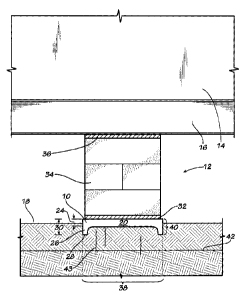
With reference to the drawings, in which like elements have like identifiers,
the
present invention provides a thermal isolator ground pan 10 for use with a
foundation
generally 12 of a manufactured buildings 14. Manufactured buildings have at
least one
longitudinally extended support beam 16, and typically two, or more, such
support
beams. The ground pan 10 seats on the ground generally 18. The ground pan 10
interacts with the ground 18 for resisting movement. Typically, this is
accomplished by
providing ground blades 20 that extend in a first direction substantially
perpendicularly
from a top surface of the ground pan. For example, opposing side edges of the
ground
pan 10 fold over to define a pair of opposing ground blades 20 that extend a
first
distance 24 from the top surface. In the illustrated embodiment, the ground
pan 10 is
formed from a metal sheet. The ground pan 10 includes ground blades that
extend from
a perimeter of the ground pan and includes a plurality of legs 26, with each
leg
extending from adjacent ground blades at intersections thereof. The legs 26
extend to a
distal extent 28 that is a second distance 30 from the top surface, with the
second
distance 30 greater than the first distance 24.
A CMD 1882230 v 1
2825894-000010 05/08/2010
CA 02703536 2015-05-29
- 6 -
The ground pan 10 includes a thermally insulative member 32. In the
illustrated
embodiment, the thermally insulative member 32 is a sheet that sits on the top
surface
of the ground pan 10, and can be attached such as with an adhesive. The
thermally
insulative sheet 32 is a foam sheet such as a STYROFOAM panel or sheet. In an
alternate embodiment, the thermally insulative sheet 32 is defined by a spray-
on thermal
material. The spray-on thermal material sticks or attaches to the ground pan.
In an
alternate embodiment, the thermally insulative sheet (or spray-on material)
seats
inwardly on a bottom surface of the ground pan. The sheet 32 provides a
thermally
insulative layer or coating of between about 1/4 inch to 1/2 inch, or other
thickness
suitable for restricting thermal communication, as discussed below.
A pier 34 positioned on the ground pan 10 extends between the ground pan and
the support beam 16 for vertically supporting the support beam and for
transferring the
mass of the manufactured home to the ground pan. The pier in the illustrated
embodiment comprises a stack of concrete blocks but can be a wood beam or
other
suitable load bearing material. The pier 34 can sit on the thermal sheet 32,
or in a
pocket or opening (see 71 in Fig. 3) defined in the thermal sheet so that the
pier sits
directly on the ground pan 10.
In the illustrated embodiment, a wood pad 36 seats between an upper surface of
the pier 34 and the lower flange of the support beam 16. Conventionally, the
wood pad
36 can be tapered for wedging between the pier 34 and the support beam 16.
The ground pan 10 and the thermally insulative sheet 32 cooperatively define
in
situ a substantially axially aligned ground column generally 38 with a
thermally isolated
ground column 40 proximate the ground pan 10. The ground column 38 below a
frost
CA 02703536 2010-05-11
- 7 -
line generally 42 communicates (generally 43) ground heat into the proximate
thermally
isolated ground column 40.
With reference to Fig. 1, the foundation 12 according to the present invention
reduces movement of the ground pan 10 caused by frost heave arising from the
freezing
and thawing of moisture-laden ground engaged by the ground pan. The ground
heat
communicates 43 through the ground column 38 and into the proximate thermally
isolated ground column 40. The thermally insulative sheet 32 aligned with the
thermally isolative ground pan 10 caps the ground column 38 and restricts heat
communication from the proximate thermally isolated ground column 40 to and
through
the ground pan 10 to the atmosphere. The proximate thermally isolated ground
column
40 retains ground heat, and the proximate ground column experiences reduced
freezing
occurrences (compared to nearby portions of the proximate ground between the
ground
surface and the portion of the ground below the frost line 42). As a
consequence, the
occurrence of frost heave is reduced relative to the proximate thermally
isolated ground
column 40, and movement of the ground pan 10 is thereby reduced. The thermally
insulative sheet 32 provides a high resistance to heat communication generally
referred
to in the insulating trade as an R factor, compared to the R factor of the
ground pan
alone.
Fig. 2 illustrates in perspective view an alternate embodiment of a ground pan
50 in accordance with the present invention. The ground pan 50 is molded from
a
plastic material and defines a floor 52 with a plurality of upstanding walls
54 that define
chambers generally 56. The chambers 56 are filled with a conventional fluidal
foam
that cures to define an insulative sheet 58. In an alternate embodiment, the
chambers 56
A CMD 1882230 vi
2825894-000010 05/08/2010
CA 02703536 2010-05-11
- 8 -
are covered with a firm thermally insulative sheet or panel. The ground pan 50
is
gainfully used with a foundation for a manufactured home, as discussed above.
The
ground pan 50 and the thermally insulative sheet 58 cooperatively define in
situ the
ground column 38 and proximate thermally isolated ground column 40 relative to
the
ground pan 50 and the frost line 42. The thermally insulative sheet 58 caps
the ground
pan. 50 and restricts heat communication from the ground column 38, and thus
reduces
occurrences of freezing of the proximate thermally isolated ground column 40.
It is to be appreciated that the thermally isolative ground pan 10 finds
gainful
use in an alternate embodiment in which the pier or the foundation supports
are
elongated steel members extending between the ground pan and the support beam.
For
example the foundation can include or use lateral elongated members and/or
longitudinal elongated members (relative to a longitudinal axis of the support
beam 16).
For example, U.S. Pat. No. 6,634,150 discloses a foundation for manufactured
homes
that uses a lateral brace having a bottom end pivotably supported by the
ground pan and
a upper end pivotably attached to a beam connector adapted for clamping
attachment to
a lateral flange of a second support beam lateral of the first support beam.
U.S. Pat. No.
7,140,157 discloses a foundation system for a manufactured building for
preventing
longitudinal movement.
With reference now to the drawings, Fig. 3 illustrates in perspective view of
an
exemplary embodiment of a foundation system 60 according to U.S. Pat. No.
7,140,157,
in which the thermally isolative sheet 32 seats on the ground pan 10. The
foundation
system 60 includes a pair of rigid arms 62 and means, such as a pair of clamps
64 for
attaching an upper end of the aim to the support beam 16. Each arm 62 has a
lower end
ACME) 1882230 vi
2825894-000010 05/08/2010
CA 02703536 2010-05-11
-9-
66 and an upper end 68. Each lower end 66 and upper end 68 includes a bore for
receiving a fastener, for pivotable support of the lower end to a connector 70
(such as a
U-shaped bracket) attached to the ground pan and for pivotable attaching of
the upper
end 68 to the beam connector 64 connected to the beam 16. The arms 62 may be
of any
suitably strong material, such as of one and one-half inch square steel tube.
The ground
pan 10 restricts downward and horizontal movement of the lower ends 66 of arms
62
and retains the lower ends in a fixed, but pivotable, position. In an
alternate
embodiment, the arms 62 are telescoping for selective length.
During use of the foundation system 60, the arms 62 communicate loading and
wind forces to the ground pan 10, while the ground pan and the thermally
insulative
sheet 32 cooperatively define in situ the ground column 38 and the proximate
thermally
isolated ground column 40 relative to the ground pan 40 and the frost line 42.
The
thermally insulative sheet 32 caps the ground pan 10 and restricts heat
communication
from the ground column 38, and thus reduces occurrences of freezing of the
proximate
thermally isolated ground column 40. It is to be appreciated that an alternate
embodiment can have a single arm 62 (not illustrated) connected to a load
bearing
ground pan 40 using a pier, and gainfully use the termally insulative sheet
32.
Fig. 4 illustrates in perspective view a foundation 70 providing lateral wind
resistance in accordance with a foundation of a type disclosed in U.S. Pat.
No.
6,634,150, and further with the thermally isolative sheet 32. The manufactured
building
14 includes a pair of spaced-apart support beams 16a and 16b, such as a
typical I-beam
having a vertical web 72 and opposing upper and lateral flanges 74, 76. The
ground pan
10 is disposed under a first of the support beams 16a with the insulative
sheet 32. The
A CMD 1882230 vi
2825894-00001005/08/2010
CA 02703536 2010-05-11
- 10..
pier 34 extends upwardly to contacting engagement with the support beam 16a. A
lateral brace assembly 78 such as elongated struts or telescoping metal tubes
79a, 79b
pivotably attaches at a lower end 80 to a connector 82 attached to the ground
pan 10.
An upper end 84 pivotably attaches to a beam connecter 86 attached to the
second
support beam 16b. A fastener such as a bolt connects the telescoping tubes
together.
During use of the foundation system 70, the elongated struts 79 in the lateral
brace assembly communicate loading and wind forces to the ground pan 10, while
the
ground pan 10 and the thermally insulative sheet 32 cooperatively define in
situ the
ground column 38 and the proximate thermally isolated ground column 40
relative to
the ground pan 10 and the frost line 42. The thermally insulative sheet 32
caps the
ground pan 10 and restricts heat communication from the ground column 38, and
thus
reduces occurrences of freezing of the proximate thermally isolated ground
column 40.
It is to be appreciated that a foundation may readily provide both lateral and
longitudinal load resistance by using a longitudinal strut or arm 62 as
illustrated in Fig.
3 together with a lateral strut assembly 78 as illustrated in Fig. 4, while
providing with
the thermal sheet 32 reduced occurrences of frost heave movement of the
foundation.
Fig. 5 illustrates in a detailed perspective view an alternate embodiment of a
thermal isolator foundation plate 90 using the thermally insulative sheet 32.
The
foundation plate 90 includes openings 92 for receiving stakes 94 to secure the
plate to
the ground 18.
Fig. 6 illustrates a detailed perspective view of the ground pan 10 with an
alternate embodiment in which the thermally isolative member is a cap 96 in
accordance with the present invention. In this embodiment, the thermally
insulative cap
A CMD D382230 vl
2825894-000010 05/08/2010
CA 02703536 2010-05-11
-11-
96 (depicted in cut-away view) has a planar sheet 98 and side walls 100
extending in a
first direction substantially normal from perimeter edges. This defines an
interior cavity
102 for receiving the ground pan 10 while the side walls 10 align contactingly
with the
walls 20 of the ground pan. The walls 100 may in alternate embodiments taper
outwardly relative to a perimeter edge of the sheet 98.
As with the embodiments discussed above and also with reference to Fig. 1, the
thermally insulative sheet 32 (Fig. 5) and the thermally insulative cap 96
(Fig. 6) form
in situ the ground column 38 and the proximate thermally isolated ground
column 40
relative to the ground plate 90 or ground pan 10 and the frost line 42. The
thermally
insulative sheet 32 caps the ground plate 90 or ground pan 10 and restricts
heat
communication from the ground column 38, and thus reduces occurrences of
freezing of
the proximate thermally isolated ground column 40.
While the present invention is applied with disclosed foundations having
ground
pans, it is to be appreciated that the thermal insulative member can readily
be used with
other anchoring members such as helical shafts or anchors that connect to
support
beams of the manufactured building for resisting loads.
The present invention accordingly provides the foundation for manufactured
buildings with the ground pan to cooperatively with the thermally insulative
sheet for
defining the proximate thermally isolated ground column to cap communication
of
ground heat therefrom and thereby resist frost heave occurrences. While this
invention
has been described in detail with particular references to illustrated
embodiments
thereof, it should be understood that many modifications, additions and
deletions, in
A CMD 1882230 vi
2825894-000010 05/08/2010
CA 02703536 2015-05-29
- 12 -
additions to those expressly recited, may be made thereto without departure
from the
scope of the invention, as set forth in the appended claims.