Note: Descriptions are shown in the official language in which they were submitted.
CA 02703551 2010-04-22
WO 2009/067625 PCT/US2008/084237
AIR COLLECTOR WITH FUNCTIONALIZED ION EXCHANGE
MEMBRANE FOR CAPTURING AMBIENT CO2
The embodiments of the present invention in one aspect relates to removal of
selected gases from air. The embodiments of the invention have particular
utility for the
extraction of carbon dioxide (CO2) from air and will be described in
connection with
such utilities, although other utilities are contemplated, including the
sequestration of
other gases including NOX and S02.-
There is compelling evidence to suggest that there is a strong correlation
between
the sharply increasing levels of atmospheric CO2 with a commensurate increase
in global
surface temperatures. This effect is commonly known as Global Warming. Of the
various sources of the CO2 emissions, there are a vast number of small, widely
distributed emitters that are impractical to mitigate at the source.
Additionally, large
scale emitters such as hydrocarbon-fueled power plants are not fully protected
from
exhausting CO2 into the atmosphere. Combined, these major sources, as well as
others,
have lead to the creation of a sharply increasing rate of atmospheric CO2
concentration.
Until all emitters are corrected at their source, other technologies are
required to capture
the increasing, albeit relatively low, background levels of atmospheric CO2.
Efforts are
underway to augment existing emissions reducing technologies as well as the
development of new and novel techniques for the direct capture of ambient CO2.
These
efforts require methodologies to manage the resulting concentrated waste
streams of CO2
in such a manner as to prevent its reintroduction to the atmosphere.
The production of CO2 occurs in a variety of industrial applications such as
the
generation of electricity power plants from coal and in the use of
hydrocarbons that are
typically the main components of fuels that are combusted in combustion
devices, such
as engines. Exhaust gas discharged from such combustion devices contains CO2
gas,
which at present is simply released to the atmosphere. However, as greenhouse
gas
concerns mount, CO2 emissions from all sources will have to be curtailed. For
mobile
sources the best option is likely to be the collection of CO2 directly from
the air rather
than from the mobile combustion device in a car or an airplane. The advantage
of
removing CO2 from air is that it eliminates the need for storing CO2 on the
mobile
device.
Extracting carbon dioxide (C02) from ambient air would make it possible to use
carbon-based fuels and deal with the associated greenhouse gas emissions after
the fact.
Since CO2 is neither poisonous nor harmful in parts per million quantities,
but creates
1
CA 02703551 2010-04-22
WO 2009/067625 PCT/US2008/084237
environmental problems simply by accumulating in the atmosphere, it is
possible to
remove CO2 from air in order to compensate for equally sized emissions
elsewhere and
at different times.
Various methods and apparatus have been developed for removing CO2 from air.
In one prior art method, air is washed with a sorbent such as an alkaline
solution in tanks
filled with what are referred to as Raschig rings that maximize the mixing of
the gas and
liquid. The CO2 interacts with and is captured by the sorbent. For the
elimination of
small amounts of C02, gel absorbers also have been used. Although these
methods are
effective in removing C02, they have a serious disadvantage in that for them
to
efficiently remove carbon dioxide from the air; the air must be driven past
the sorbent at
fairly high pressures.
The most daunting challenge for any technology to scrub significant amounts of
low concentration CO2 from the air involves processing vast amounts of air and
concentrating the CO2 with an energy consumption less than that that
originally
generated the CO2. Relatively high pressure losses occur during the scrubbing
process
resulting in a large expense of energy necessary to compress the air. This
additional
energy used in compressing the air can have an unfavorable effect with regard
to the
overall carbon dioxide balance of the process, as the energy required for
increasing the
air pressure may produce its own CO2 that may exceed the amount captured
negating the
value of the process.
Prior art methods result in the inefficient capture of CO2 from air because
these
prior art methods heat or cool the air, or change the pressure of the air by
substantial
amounts. As a result, the net reduction in CO2 is negligible as the capture
process may
introduce CO2 into the atmosphere as a byproduct of the generation of
electricity used to
power the process.
In co-pending U.S. Application Serial No. 11/683,824, filed March 8, 2007,
U.S.
Publication No. U.S.-2007-0217982-A1, assigned to a common assignee, there is
described an air capture device that utilizes a solid functionalized anion
exchange
material that is formed to provide a relatively large surface area which
allows for air
flow. The solid anion exchange material may be formed from membranes of anion
exchange material such as functionalized polystyrene or the like, or comprise
membranes
of inert substrate material coated with anion exchange material. In a
preferred
embodiment of our prior invention, the anion exchange material comprises
"noodle-like"
1 mm thick by 1 mm wide strands formed by slitting commercially available
anion
2
CA 02703551 2010-04-22
WO 2009/067625 PCT/US2008/084237
exchange membrane material available from Snowpure, LLC, San Clemente,
California.
The manufacturer describes this membrane material as comprising crushed
anionic
exchange resin mixed in a polypropylene matrix and extruded as a membrane
according
to the teachings of U.S. Patent Nos. 6,503,957 and 6,716,888. The solid anion
exchange
polymer also maybe formed into cells or the like.
The present invention explores alternative solid ion exchange materials for
currently utilized ion exchange materials as above described as solid sorbent
materials
for CO2 air-capture. More particularly, there is provided a process for
forming solid
sorbent materials for CO2 air capture by immobilizing solid CO2 sorbent
materials in or
on a support. In a preferred embodiment of the invention the solid CO2 sorbent
materials
comprise solid particulate sorbent materials held together in a porous matrix.
Alternatively, the solid CO2 sorbent materials may comprise solid particulate
sorbent
materials supported on a surface of a support matrix. The support matrix may
take a
form of a membrane, which may be cut or slit into elongate elements, fiber
strands which
may be ordered or unordered, various geometric shapes such as tubes or bundles
of
tubes, honeycombs, discs or the like.
Further features and advantages of the present invention will be seen from the
following detailed description taken in conjunction with the accompanying
drawings,
wherein like numerals depict like parts, and wherein:
Figure 1 is a three-dimensional depiction of a polymer matrix of the prior art
Snowpure membrane showing resin beads interspersed throughout the matrix.
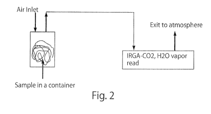
Figure 2 is a schematic depiction of the C02/H20 vapor measurement device
apparatus used in this investigation.
Figure 3 shows the PSU-resin membrane before gelling.
Figure 4 shows the PSU-resin membrane after the final membrane formation.
Figure 5 is a graph showing the CO2 adsorption capacity or desorption kinetics
of
a 0.78 gram sample of a PSU-resin composite membrane. Adsorption capacity of a
sample in the chamber can be estimated from the area between the horizontal
dashed line
representing the atmospheric concentration of CO2 (-400 ppm), and the
adsorption
curve, which shows the amount of CO2 being adsorbed by the membranes as the
400
ppm CO2 air goes through the chamber.
Figure 6 is another graph of CO2 versus time showing a CO2 adsorption of the
reference membrane Snowpure, 1.13 g.
2
CA 02703551 2010-04-22
WO 2009/067625 PCT/US2008/084237
Figure 7 is a graph of CO2 versus time showing the CO2 adsorption capacity of
two membranes, the Snowpure 1.13g reference membrane, and a PSU PVP 1.03 g
membrane.
Figure 8 is a graph of CO2 versus time showing the CO2 adsorption capacity of
two membranes, the same Snowpure reference membrane plotted with a PVDF - HFP
0.88 g membrane.
Figure 9 is a graph of CO2 versus time showing the CO2 desorption pattern that
occurs when air saturated with water vapor is purged through the chamber.
Figure 10 is a graph of CO2 versus time showing the VBC/styrene ratio equal to
one as air is purged through it to dry the membrane.
Figure I I is a graph of CO2 versus time for the membrane and VBC\styrene
equal to one with a water vapor purge through the chamber.
Figure 12 is a graph of CO2 versus time for the VBC/styrene ratio equal to one
air
purge of the membrane in the chamber.
Figure 13 is a graph of CO2 versus time showing the behavior of the sample
VBC/styrene ratio equal to two when air is purged through the chamber
containing the
sample membrane.
Figure 14 is a graph of C02 versus time for the VBC/styrene ratio equal to two
sample membrane with a high humidity air purge.
Figure 15 is a graph of CO2 versus time for her the membranes and VBC only,
2.7 g, and the snow pure 2.9 Graeme membrane.
Figure 16 is a graph of CO2 concentration versus time for the sample
polyester/cotton thread VBC only, 2.0 g, with a dry air purge.
In order to develop alternative methods for forming solid CO2 sorbent
materials
we first needed to better understand the structure of the currently utilized
commercially
available materials and the reasons why such materials are capable of
absorbing C02, As
best understood from the aforesaid U.S. Patent Nos. 6,503,957 and 6,716,888,
the
Snowpure materials are made by a thermal extrusion method using polypropylene
as the
support matrix and ground anion exchange resin powder as an active filler. The
polypropylene polymer is hydrophobic so it can afford physical support and not
be
soluble in aqueous solutions. The polypropylene polymer matrix has a narrow
molecular
weight distribution and low melting point (125130 C, although usually
polypropylene
melts at around 160 C). The low melting temperature helps avoid thermal
decomposition
4
CA 02703551 2010-04-22
WO 2009/067625 PCT/US2008/084237
of the resin powders during the extrusion process. Also the polypropylene
matrix is
stable under chemical conditions such as high basicity or acidity.
According to the aforesaid U.S. patents of Snowpure, in the manufacturing
process described by Snowpure, the polypropylene is melted in an extruder, and
the resin
powders are added into the melted polymer together with glycerin. The resin
particles are
hydrophilic and have exchangeable ions when wet. Glycerin is believed to help
disperse
the resin particles in the polymer matrix and form a barrier layer between
resin and
polymer. After extrusion, the membrane is soaked in an 80 C water bath to
remove the
glycerin and to fully expand the resin. The structure is called a "composite"
membrane
because it consists of two phases, the polypropylene polymer matrix and the
agglomeration of resin powders which it is believed forms continuous channels
in the
polymer. Figure 1 is a simplified representation of the basic structure of the
material
obtained from Snowpure, except that the volume fill of the resin is much
larger than
depicted below.
The continuous channel shown by the continuous resin beads is believed to be
important for membrane function in the Snowpurc material. If the resin
agglomerations
are discontinuous or separated from each other and surrounded by polymer, the
final
membrane would be hydrophobic and would not be able to conduct ions in water
or
adsorb CO2 at all.
The following examples describe alternative methods for forming solid sorbent
materials for CO2 air capture:
A first method of fabrication is based on solvent casting techniques.
This process starts with a polymerizable monomer or polymer in a liquid
carrier
having dispersed therein particles of a solid CO2 sorbent material. There are
two major
properties for the polymerizable monomers used in this method. First, the
polymerizable
monomer or monomer blend or polymer should be soluble in the liquid carrier;
second,
the polymerizable monomer or monomer blend or polymer should be able to form a
polymer sheet or film. Amongst preferred polymers are mentioned polybisphenol-
A-
carbonate, poly(ethylene terephthalate), polystyrene, poly(methyl
methacrylate),
poly(vinyl acetate), poly(vinyl chloride), polytetrafluoroethylene,
polysulfone,
poly(vinylidene fluoride), styrene/butyl acrylate/methacrylte acid terpolymer,
and
poly(vinylidene fluoride-co-hexafluoropropylene).
The solid CO2 sorbent materials are materials capable of absorbing and
releasing
gaseous CO2 under controlled conditions. The solid CO2 sorbent materials may
comprise
5
CA 02703551 2010-04-22
WO 2009/067625 PCT/US2008/084237
solid ion exchange resins such as described in US Patent Nos. 6,503,957 and
6,716,888,
as well as solid CO2 sorbents or "getters" such as strong base Type 1 and Type
2
functionality ion exchange materials as are available commercially from a
variety of
vendors including Dow, Dupont and Rohm and Haas.
A mixture of the polymerizable monomer or monomer blend or polymer and the
solid CO2 sorbent material is mixed with the solid sorbent materials and
liquid carrier,
and applied in a solvent casting method. The monomer or monomer blend or
polymer is
dissolved and the solid CO2 sorbent materials particles are homogeneously
dispersed in
the liquid carrier. When the mixture is poured on a flat surface, e.g., a
stainless steel
block on a hot plate, and the liquid carrier evaporated, a sheet or film
having the particles
dispersed throughout is left on the surface. However in this method the
structure of the
sheet is determined by the interactions among the liquid carrier, the monomer
or
monomer blend and the particles.
In one experiment we made a sheet by mixing poly(vinylidene fluoride) and
resin
particles in dimethylformamid (DMF). The ion-exchange resin is ground or
chopped to
particle size of 100 to 1000 microns, preferably 200 to 500 microns. The resin
particles
should comprise 10 to 90 volume percent of the cast film, preferably 20 to 80
volume
percent. The finished sheet preferably has a thickness of 0.1 to 2.0 mm,
preferably 0.2 to
1.0 mm. Experiments showed that without glycerin addition the sheet with even
50%
resin content is still hydrophobic, which indicates the particle
agglomerations are
separated by polymer. When glycerin or phenolphthalene is added into the
monomer,
filler and liquid carrier mixture, the sheets formed are hydrophilic and ion-
conductive.
Fig. 2 is an CO2 absorption curve of both membranes under similar conditions.
A second method of fabrication of polymer membranes is the phase
inversion/immersion precipitation method. Phase inversion methods are
described
generally in U.S. Patents 3,876,738, 4,340,480, 4,770,777, and 5,215,662, all
of which
are incorporated herein by reference. Generally, the process is to immerse a
polymer
solution made by a polymer dissolved in a solvent or mixture of solvents into
a miscible
non-solvent such as water (i.e., a liquid in which the polymer is not soluble,
but the non-
solvent is miscible with the solvent). In a non-solvent such as a water bath,
the polymer
starts to solidify because of the penetration of water molecules whereas the
solvent
component diffuses into the water, leaving spaces throughout the polymer where
the
solvent formerly was. Thus the formed membrane is asymmetric. The surface of
the
membrane has a relatively dense gel surface, while the bulk interior of the
membrane is
6
CA 02703551 2010-04-22
WO 2009/067625 PCT/US2008/084237
relatively porous. Spaces formed by this method are interconnecting, however.
The
phase inversion technique has been established for about twenty years. Reverse
osmosis
and nanofiltration membranes are also made using this technique. It is also
applied in
hollow fiber membranes for pervaporation separation of ethanol/water solutions
or gas
separations. In our application the porous structure enables the easy access
of air to the
resins embedded in the polymer matrix.
A third method of fabrication of polymer membranes is the sorption method in
which a mixture of liquid monomers and initiators are absorbed in a woven or
non-
woven fiber matrix of polypropylene, PVC, polyester, cellulose etc. The
monomers
polymerize under thermal or radiation conditions forming a thin layer on the
matrix
surface. Mizutani, Y., Journal ofMembrane Science, 1990, 49, 121-144 reported
the
preparation of an ion exchange membrane using the paste method, in which the
paste,
consisting of monomers and finely powdered PVC was coated onto PVC cloth and
the
cloth was exposed to heat. Later Choi et. al. published papers describing the
making of
ion exchange membranes by the sorption method, in which monomers were absorbed
in
non-porous reinforcing materials such as polypropylene, or PVC Films. Choi,
Y., et al.,
Desalination, 2002, 146, 287-291; Choi, Y. et al., Journal ofMembrane Science,
2003,
221, 219-231; Choi, Y., et al., Journal of Membrane Science, 2003, 223, 201-
215, The
non-porous reinforcing material was swollen while monomers were absorbed in
non-
porous reinforcing materials. The swollen reinforcing material permitted
enlarged free
volume for the adsorbed monomers. The membrane was treated with UV radiation
for
monomer polymerization (anion exchange membranes). In our experiments
solutions of
monomers such as vinylbenzyl chloride, styrene, divinylbenzene and the
initiator
benzoyl peroxide were absorbed into non porous or porous fabrics such as
filter paper,
polyester/cellulose paper, cloth etc, or porous film such as porous alumina,
polycarbonate etc. through capillary action. The solution-saturated fabrics
were then
exposed to heat or radiation to polymerize the monomers. The resulting
membranes in
carbonate form showed moisture swing effects in absorbing CO2 from the
atmosphere.
Materials and Methods.
The following protocols or material preparation processes recur throughout the
Examples, and so they are presented here for purposes of streamlining the
disclosure of
the various embodiments.
7
CA 02703551 2010-04-22
WO 2009/067625 PCT/US2008/084237
1) Amination protocol. Synthetic membranes were soaked in a 40% aqueous
solution of trimethylamine for 10 hours at 50 C. They were then rinsed with
tap water,
and placed twice in 100 ml 0.1 M HCI solution to neutralize any residual
unbound
trimethylamine. At this point the counterion on the membrane is chloride, and
the
chloride was exchanged with carbonate via the carbonation process (see below).
Carbonation protocol. Samples in the chloride form are exchanged with
carbonate counterion by immersing them in 0.5 M Na2CO3 with stirring for 30
minutes
twice at room temperature, and then rinsing with DI water until neutral.
Polymer loading capacity. A supporting matrix should be chemically and
mechanically stable through all polymerization and derivatization processes
and should
be loaded with the highest amount of coated polymers. We define "loading
capacity of a
matrix" as (weight of net polymers coated on matrix)/ (weight of net matrix).
Ion exchange capacity measurement process. Sample membranes made
hereunder had their Ion Exchange Capacity ("IEC") measured to test their
efficiency of
CO2 adsorption. IEC is defined as the total amount of ion groups per unit mass
of dry
material (mmol/g). The higher the JEC number the higher the corresponding CO2
absorption capacity. Generally, samples were heated in an oven at about 60 C
until dry
(no more weight loss). About 1.0 g of dried sample was weighed and soaked in
20 ml
0.5M NaNO3 solution for 30 minutes with stirring. The sample was filtered and
soaked
in another fresh 20 ml 0.5M NaNO3 solution for another 30 min. with stirring.
All
filtered solutions were collected and were titrated to pH 7 with 0.1 M
standard HC1
solution. The total ionic numbers could be deduced from the titration results
and IEC
could be calculated as a ratio: total ionic number (mmols)/dried sample weight
(grams).
CO2/H)O measurement process. Fig. 2 is a schematic of the C02/H20 vapor
measurement device used in this investigation. In order to compare samples
created
hereunder against the Snowpure standard material accurately in terms of their
CO2
adsorption ability, the same or similar weight of samples or Snowpure were
sealed in a
container (glass jar, 0.25 liter) with two vents. In order to dry or hydrate
the membranes,
air (absolute humidity -5 ppt) or air saturated with moisture vapor (absolute
humidity
30 ppt) was pumped into and through the container at a fixed flow rate
(usually
O.1L/min) at 75 F and was passed through the glass jar containing the sample
material.
The exiting air is then directed through an IRGA (IR Gas Analyzer, Model LI-
840, LI-
COR, Inc.), which detects CO2 and H2O vapor content at selected intervals,
usually every
10 seconds. The air is then vented to atmosphere.
8
CA 02703551 2010-04-22
WO 2009/067625 PCT/US2008/084237
Phase inversion method. Materials: DMF (dimethyl formamide) solvent (95%);
PSU (polysulfone) pellets (Aldrich, P/N 428302, Mw-35,000); PVDF powder
(poly(vinylidene fluoride), Aldrich, P/N 182702, Mw-534,000); PVP
(Polyvinylpyrrolidone, Sigma-Aldrich, Mw-10,000); PVDF-HFP (poly(vinylidene
fluoride-co-hexafluoropropylene) and Dowex Marathon A anion exchange resin Cl
form (SigmaAldrich, P/N 433942). Resin beads were ball milled to 40100 microns
at
room temperature before use. Polymer matrix materials that may be used herein
include
but are not limited to polybisphenol-A-carbonate, poly(ethylene
terephthalate),
polystyrene, poly(methyl methacrylate), poly(vinyl acetate), poly(vinyl
chloride),
polytetrafluoroethylene, polysulfone, polyether sulfone, poly(vinylidene
fluoride),
styrene/butyl acrylate/methacrylic acid terpolymer, and poly(vinylidene
fluoride-co-
hexafluoropropylene). Preferred organic solvents for the polymers may be
selected from
dimethylformamide or tetrahydrofuran, or N-methylpyrrolidone (NMP). Glycerin,
polyvinyl pyrolidone (PVP), dibutylphthalate (DBP), phenolphthalene or other
plasticizers may be added to the mixture. For the phase inversion procedure,
the
aqueous-based solution may be water or methanol, ethanol, isopropanol or
mixtures
thereof The resin particles used in the composite membranes may vary in
diameter from
10100 micrometer and the resin content may vary from 2080% of polymer matrix
by
weight, preferably 30-60%. The final heterogeneous membrane thickness may vary
from
0.1 -1.0 mm, preferably 0.5 mm.
Example I- Phase Immersion of PSU-resin membrane
PSU-resin membrane: 0.5 g of PSU pellets were weighed in a 20 ml vial, 2.5 ml
of DMF was added into the vial and the mixture was stirred until the polymer
dissolved
in the DMF. In another vial 0.5 g of ground ion-exchange resin powders were
weighed
and 2.0 ml of DMF was added. The mixture was stirred until homogeneous. The
two vial
contents were combined and stirred for another half hour. The mixture was cast
on a
rectangular 6x4 inch stainless steel block surface on a hot plate maintained
at 50 C. In
about 10 minutes the membrane completely gelled (the membrane looked
transparent at
this time and there was no liquid solvent on the surface). The block was
removed from
the hot plate, allowed to cool to room temperature and then soaked in a
deionized water
bath (2 liters). After several minutes, the membrane was peeled from the
block. The
membrane was left in the water bath with stirring for two days (the water in
the bath was
changed after one day) and boiled in hot water for 1 hour to get rid of any
residual
9
CA 02703551 2010-04-22
WO 2009/067625 PCT/US2008/084237
solvent inside the membrane. The membranes are then carbonated by the general
carbonation protocol.
Figures 3 and 4 show the PSU-resin membrane before gelling and after the final
membrane formation, respectively. The IRGA measures the air that has contacted
the
membrane, and thus reflects the membrane's CO2 adsorption capacity in real
time.
Snowpure membranes are used as the standard CO2 absorbent material against
which
the inventive membranes described herein are compared against.
Results:
With respect to Figure 5 and Figure 6, the CO2 adsorption capacity of a given
membrane in the chamber can be estimated from the area between the horizontal
dashed
line representing the atmospheric concentration of CO2 (-400 ppm), and the
adsorption
curves, which show the amount of CO2 being adsorbed by the membranes as the
400
ppm CO2 air goes through the chamber. Simply, we can cut the areas and measure
paper
weight. The ratio of paper weights between the membranes being compared is
directly
proportional to CO2 capacity if the sample weights are similar. This is also
known as the
integral of the area under the 400 ppm curve and above the CO2 adsorption
curve.
From Figs. 5 and 6, the C02 capacity of the PSU membrane is smaller than that
of the Snowpure sample (absorption area per unit weight of PSU is smaller than
that of
Snowpure). Theoretically with the same amount of resin the membranes should
absorb
the same quantity of CO2. One possible reason for the lower CO2 absorption by
the
PVDF- and the PSU-resin-C03 membranes compared to the Snowpure membranes is
that the resin particles are more tightly surrounded by polypropylene polymer.
One way
to resolve this is to make the membranes more porous. In the following
experiment we
added PVP (polyvinylpyrrolidone) into the mixture before casting. PVP is
soluble in
both polar aprotic solvent and water. After the membrane is cast and later
soaked in
water, the PVP mixed with the water and left pores inside the membrane.
Example II- Phase Inversion aided by PVP
Membrane (PSUPVP ) preparation: 0.5g of PSU was weighed in a 20 ml vial and
2.5 ml DMF was added and the mixture stirred until all polymers were
dissolved. 0.5g
of resin and 0.2g of PVP was weighed in another vial and 2.5 ml DMF was added.
The
mixture was stirred until homogeneous. The two vial contents were combined and
stirred
for another 0.5 hour at room temperature. The mixture was cast on the same
rectangular
stainless steel block surface, 6x4 inches on a hot plate at 50 C. After about
10 minutes,
CA 02703551 2010-04-22
WO 2009/067625 PCT/US2008/084237
the membrane completely gelled (the whole membrane appears transparent at this
time
and there was no flowing solvent on the surface). The block was removed from
the hot
plate, allowed to cool to room temperature, and then soaked in a deionized
water bath.
After several minutes, the membrane was peeled from the block. The membrane
then
was left in the water bath with stirring for two days (the water in bath was
changed after
one day) and boiled in hot water for 1 hour to eliminate the solvent and any
PVP inside
the membrane. The membrane was then carbonated according to the standard
protocol.
Results:
From Fig. 7 the C02 adsorption capacity of PSUPVP membrane is much bigger
than that of the PSU membrane in Experiment I, which indicates that the
addition of PVP
increases membrane porosity. The IEC value is 1.90 mmol/g. A comparison was
made
of the CO2 adsorption for this PSUPVP membrane to the membrane material from
Snowpure (Fig. 7) which also has an lEC value of 1.9. Numerical estimates of
the CO2
uptake for the Snowpure material and PSUPVP membrane based on the integral of
the
CO2 deficit in the exhaust stream suggest that the total uptake capacities are
quite
similar. We conclude that the PSUPVP membrane has comparable CO2 absorption
capacity to the Snowpure .
Except for PSU polymer, other thermal plastic polymers could also be used as
matrix via phase immersion process.
Example III- Phase Immersion of PVDF-HFP membrane
Membrane (PVDF-HFP ) preparation: 0.5g of PVDF-HFP were weighed in a 20
ml vial and 3.0 ml DMF was added and the mixture stirred until all polymers
were
dissolved. 0.5g of resin was weighed in another vial and 2.0 ml DMF was added.
The
mixture was stirred until homogeneous. The two vial contents were combined and
stirred
for another 0.5 hour at room temperature. The mixture was cast on the same
rectangular
stainless steel block surface, 6x4 inches, on a hot plate at 50 C. After about
10 minutes,
the membrane completely gelled (the whole membrane appears transparent at this
time
and there was no flowing solvent on the surface). The block was removed from
the hot
plate, allowed to cool to room temperature, and then soaked in a deionized
water bath.
After several minutes, the membrane was peeled from the block. The membrane
then
was left in the water bath with stirring for two days (the water in bath was
changed after
one day) and boiled in hot water for 1 hour to eliminate the solvent and any
remaining
11
CA 02703551 2010-04-22
WO 2009/067625 PCT/US2008/084237
PVP inside the membrane. The membrane was then carbonated according to the
standard protocol.
Results: PVDF-HFP membrane shows comparable C02 absorption ability of
Snowpure in Fig. 8 with no addition of PVP. This membrane has a IEC of 1.85.
B. Sorption method
In the following embodiments solutions of monomers such as vinylbenzyl
chloride, styrene, divinylbenzene and the polymerization initiator benzoyl
peroxide were
absorbed into non-porous fabrics such as filter paper, polyester/cellulose
paper, cloth,
etc, or porous film such as porous alumina, polycarbonate film, etc. through
capillary
action. The solution-saturated fabrics were then exposed to heat or radiation
to
polymerize the monomers. The resulting membranes in carbonated form showed
moisture swing effects in absorbing and de-sorbing CO2 from the atmosphere.
Reagents:
Vinyl benzyl chloride (VBC.. Aldrich, 97%), Styrene (Sigma-Aldrich, 99%),
Divinyl benzene (Aldrich, 80%) and Benzoic acid (Fluka, 99%) were all dried by
passing
them through an A1203 column and stored at O'C and purired by
recrystalization.
Benzoyl peroxide (powder) in a beaker was dissolved in a minimum amount of
chloroform. The solution was transferred into a separation funnel. The
solution was
separated into two layers. The water layer was on top and bottom layer was BP-
chloroform solution. The bottom layer was collected in a clean beaker and
methanol was
added until no more precipitation occurred. The solvent was decanted and white
precipitate was purged under N2 and stored in a desiccator.
Example IV: Membranes synthesized from polyester/cellulose matrixes
1.5 ml VBC, 1.5 ml styrene, 0.3 ml divinylbenzene and 0.02g BP were added into
a 20 ml vial and were stirred until all BP was dissolved at room temperature.
The mixed
solution was poured onto Durx 670 polyester/cellulose papers and was spread
on the
paper under capillary effect. The wet papers were put in a closed glass
container and
were purged with N2 to eliminate residual 02 in the container. The container
was placed
in an oil bath and heated to about 68 - 70'C for 10 hours. After reaction
completion, the
container was cooled to room temperature and was left open for 2-3 hours to
evaporate
excess reagents. The membranes were soaked in 40% trimethylamine aqueous
solution
12
CA 02703551 2010-04-22
WO 2009/067625 PCT/US2008/084237
for 3 hours at 30CC to aminate them and then were rinsed with tap water. The
aminated
membranes were soaked in 2x 100 ml 0.IM HC1 solution to wash off any excess
trimethylamine, and then rinsed with tap water. Finally the membrane was
carbonated
by soaking in 0.5 M Na2CO3 2x100 ml. The final product was rinsed with water
until
neutral before use.
VBC was the reagent utilized to enable the subsequent addition of functional
amine groups via amination to the final product. Para- or ortho-VBC, or
mixtures of
both, function adequately. Styrene was the non-functional matrix polymer that
increased
hydrophobicity of the membrane. Divinyl benzene was the cross-linking reagent,
and
BP was the initiator for the polymerization reaction. The VBC and styrene
ratio could be
changed from 100% VBC to 10% VBC, according to product requirements. The cross-
linking percentage could be changed from 2% to 20% of total VBC and styrene
weight.
Reaction vessels can be made from glass, stainless steel or ceramic.
Membrane CO2 binding performance:
For membrane measurements of CO2 adsorption capacity, samples were sealed in
the 250 ml glass jar mentioned previously and were purged with air at 0.1
L/rnin flow
rate. The measurement protocol was described previously. Figures 9-12 are
measured
from a single sample weighing 3.5g having an IEC of 0.55 mmol/g.
In Figures 9-12, the 3.4 g sample was purged by dry air (Fig. 9) followed by
moisture saturated air (Fig. 10). The process was repeated once (Figs. 11-12).
With
atmospheric CO2 levels at about the 390 ppm level, the sample showed a
repeatable
"moisture swing" C02 adsorption/desorption effect: when the membrane sample
was
purged by relatively dry air (absolute humidity - 5 ppt), the membrane
adsorbed C02;
when the sample was purged with moisturized air (absolute humidity 30 ppt), it
gave off
or desorbed CO2.
In Figs. 9-12, during sample preparation the VBC to styrene ratio was 1. Under
the same reaction conditions but varying the VBC to styrene ratio, it is
expected to help
increase the membrane's CO2 absorption capacity, as shown by the following
example.
Example V: Membranes synthesized from polyester/cellulose matrixes-effect of
increase
in VBC content
In this experiment samples were made under the same conditions as in
experiment IV except that VBC and styrene were present at a 2:1 ratio
respectively. The
sample weights in Figs. 13-14 are 4.1g. IEC is 1.35 mmol/g, which is
significantly
higher than the 1:1 ratio's 0.55 mmol/g.
13
CA 02703551 2010-04-22
WO 2009/067625 PCT/US2008/084237
In experiment V the samples were made with a higher VBC to styrene ratio
(VBC/styrene = 2) compared with samples made in experiment IV (VBC/styrene =
1).
Figures 13 and 14 demonstrate that the increased amount of VBC may have
provided
more ionic sites on the membrane thereby increasing the membrane's C02
adsorption
capacity. The resulting membranes show retention of the moisture swing effect.
When the amount of VBC was increased to 100%, the resulting samples did not
show enhanced performance. IEC titration of the sample with VBC only and the
sample
with VBC/styrene = 1 both resulted in an IEC of 1.0 mmol/g of dry sample, much
lower
than the IEC of Snowpure (1.9 mmol/g). The following method is to conduct
amination at elevated temperature (from 30 C to 50 C ) and extended reaction
time (from
3 hrs to 10 hrs).
Example VI: Membranes synthesized from polyester/cellulose matrixes-improved
roved
amination condition
3.0 ml ml VBC, 0.45 ml divinylbcnzene and 0.02g BP were added into a 20 ml
vial and were stirred until all BP was dissolved at room temperature. The
mixed solution
was poured onto Durx 670 polyester/cellulose papers and was distributed
through the
paper by the capillary effect. The wet papers were put in a closed glass
container and
were purged with N2 to eliminate residual 02 in the container. The container
was placed
in an oil bath and heated to about 68 - 70'C for 10 hours. After reaction
completion, the
container was cooled to room temperature and was left open for 2-3 hours to
evaporate
excess reagents. Instead of aminating at 30'C for 3 hours, the membranes were
soaked
in 40% trimethylamine aqueous solution for 10 hours at 50'C and then were
rinsed with
tap water. The aminated membranes were soaked 2x in 100 ml 0.1M HCI solution
to
wash off any excess trimethylamine, and then rinsed with tap water. Finally
the
membrane was carbonated by soaking in 0.5 M Na2CO3 2xl00 ml. The final product
was rinsed with water until neutral before use.
Sample membranes or Snowpure membranes were sealed in a container (glass
jar, 0.25 liter) with two vents. Dry air (atmospheric air passed through dry
silica column,
absolute humidity -0 ppt) was pumped into the container at a fixed flow rate
(0.1L/min)
at 75 F and was purged through the sample. The exiting air is then directed
through an
IRGA (IR Gas Analyzer, Model LI-840, LI-COR, Inc.), which detects CO2 and H2O
vapor content at every 10 seconds. The air is then vented to atmosphere.
14
CA 02703551 2010-04-22
WO 2009/067625 PCT/US2008/084237
Figure 15 showed that samples made under improved arnination conditions had
similar C02 absorption capacity compared with Snowpure . IEC titration of
samples
was 2.2 mmol/g, a bit higher than that of Snowpure (1.9 mmol/g).
In the above coating method, the matrix we used was polyester/cellulose
fabric.
This coating method could also be applied to fibers such as polyester thread,
nylon
thread, polyester/cotton thread etc.
Example VII: Polyester/cotton thread synthesized by ~ rption method
3.0 ml VBC, 0.45 ml divinylbenzene and 0.02g BP were added into a 20 ml vial
and were stirred until all BP was dissolved at room temperature. The mixed
solution was
dropped onto polyester/cotton thread (sewing thread, 37%cotton, 63% polyester)
and
was spread along thread under capillary effect. The wet threads were put in a
closed
glass container and were purged with N2 to eliminate residual 02 in the
container. The
container was placed in an oil bath and heated to about 68 - 70'C for 10
hours. After
reaction completion, the container was cooled to room temperature and was left
open for
2-3 hours to evaporate excess reagents. The threads were soaked in 40%
trimethylamine
aqueous solution for 10 hours at 50 C to aminate them and then were rinsed
with tap
water. The aminated threads were soaked in 2x100 ml O.1M HC1 solution to wash
off
any excess trimethylamine, and then rinsed with tap water. Finally the threads
were
carbonated by soaking in 0.5 M Na2CO3 2x 100 ml. The final product was rinsed
with
water until neutral before use.
The IEC of the coated polyester/cotton thread shown in Fig. 16 is 1.5 meq/g,
which is a relatively lower IEC compared with that of Snowpure (1.9 meq/g)
and is
from the thread having a lower polymer loading capacity defined in Protocol 3.
The loading capacity of sample matrixes were measured according to Protocol 3
and used the following matrices: braided nylon thread: 0.5; polyester/cotton
thread: 0.85;
polyester thread: 0.89 polyester/cellulose fabric: 2Ø The fabrics or fibers
such as
polyester/cellulose paper, polyester thread, polyester/cotton thread etc.
proved to be good
matrices. Light weight and high absorption material is optimal.
The methods described above, and other conceivable methods, may be used to
form various superstructures having active resins embedded therein. For
example, it is
possible using the solid sorbents and polymers or other matrices discussed
above to form
films that can be arranged in the configurations described in co-pending
application PCT
Application Serial No. PCT/US08/60672, which describes several geometries that
may
be used to form a collapsible collector to optimize the porosity of the
collector for
CA 02703551 2010-04-22
WO 2009/067625 PCT/US2008/084237
alternating liquid and gas streams. The films may be formed in flat membranes,
concentric cylinders or tubes, or wound up spirals. Some configurations may
require the
use of spacers, which may be formed of a polymer material, to form the
structure.
Other examples of superstructures that are possible using the present
invention
include the formation of flat membranes, tubes, hexagons, or monolithic
structures, using
porous materials. Porous structures will naturally increase the amount of
surface area for
CO2 uptake. Alternatively, the solid sorbent material may be produced in a
foam that
can be manipulated into complex shapes for a specific application or for
optimal
performance. In another alternative formation, the material could be spun into
thin
threads or woven into textile or felt-like materials.
The sorbent materials of the present disclosure may also be applied as surface
coating to an underlying structure formed of a durable and inexpensive
material. For
example, monoliths made out of inexpensive materials could be soaked in the
polymer/resin combination and then harden into a useful filter system. These
monoliths
may be constructed of paper materials, ceramic materials, textiles, or other
appropriate
materials. The coatings may be applied similar to a paint, such as by
spraying, rolling,
dipping, or the like.
In another aspect of the present invention, the superstructure may be formed
as
the sorbent materials are polymerized around a fibrous structure, similar to a
carbon
composite matrix structure.
The present invention may also be used to create a sorbent superstructure with
very rough surfaces, which would then increase the uptake rate of the CO2
capture
process. In particular, solvents may be used to form a dendritic structure. A
rough
surface could also be accomplished by a method involving a step of etching the
solid
material to create more surface area.
In embodiments where a high concentration of uptake sites are present, it may
be
possible to use turbulent flows through the filter, as this would decrease the
air side
transport limitations of the system.
Various changes may be made without departing from the spirit and cope of the
invention, For example, CO2 capture elements may be formed using solid amines
as the
CO2 sorbent or getter. The solid amine getters preferably are the amines as
described in
our co-pending U.S. Provisional Application Serial No. 60/989,405, filed
November 20,
2007. The solid amines may be formed on porous solid supports, membranes or
films,
e.g. from liquid amines which are dried in place on a support. Also, the
membranes and
16
CA 02703551 2010-04-22
WO 2009/067625 PCT/US2008/084237
films may be formed by roll casting, or doctor blade casting from a solution
containing
the monomer or monomer blend or polymer dissolved or a solvent containing the
particulate CO2 sorbent or getter. Also, films, membranes or fibers may be
formed by
spin coating.
17