Note: Descriptions are shown in the official language in which they were submitted.
CA 02703965 2012-12-13
DISPENSER WITH DRAW-BACK MECHANISM
CROSS REFERENCE TO RELATED APPLICATIONS
This application claims the benefit of priority under 35 U.S.C. 119(e) to
the filing date of U.S.
Provisional Patent Application No. 60/981,995 filed on October 23, 2007.
TECHNICAL FIELD
100011 The present invention relates to soap dispensers. More specifically,
the present
invention relates to counter mounted soap dispensers having a draw-back
mechanism for
preventing dripping of soap between uses.
BACKGROUND
[0002] Users of modern public washroom facilities increasingly desire that
each of the
fixtures in the washroom operate automatically without being touched by the
user's hands. This
is important in view of increased user awareness of the degree to which germs
and bacteria may
be transmitted from one person to another in a public washroom environment.
Today, it is not
uncommon to find public washrooms with automatic, hands-free operated toilet
and urinal units,
hand washing faucets, soap dispensers, hand dryers and door opening
mechanisms. This
automation allows the user to avoid touching any of the fixtures in the
facility, and therefore
lessens the opportunity for the transmission of disease carrying germs or
bacteria resulting from
manual contact with the fixtures in the washroom.
[00031 It is known to provide a counter-mounted soap dispensers in public
washrooms to
dispense liquid or foam soap automatically in response to sensing the presence
of a user.
However, these counter-mounted dispensers may allow soap to drip out of the
dispenser after a
use. This dripping creates an unappealing and messy environment and
discourages the use of the
dispenser. Thus, it is desirable to provide an improved means that prevents
leakage or dripping of
excess soap.
[0004] These and other objectives, advantages, and features of the present
invention will
CA 02703965 2010-04-23
WO 2009/055576
PCT/US2008/080970
become apparent from the following description and claims, taken in
conjunction with the
accompanying drawings.
BRIEF SUMMARY
[0005] This patent discloses tools, methods and systems for dispensing
soap. The tools,
methods and systems include a draw-back chamber constructed around and in line
with the fluid
path between a spout assembly for delivering soap to a user and a pump
mechanism for
supplying the soap. The draw-back chamber contains port openings into the
fluid path. When the
pump mechanism is actuated to dispense soap, the draw back chamber is
collapsed and soap
within it is dispensed with the main dose of soap supplied by the pump
mechanism. When the
pump mechanism is allowed to return to its extended rest state, the draw-back
chamber expands,
drawing soap into it through the port opening to prevent soap from hanging and
dripping at the
end of the dispensing tube.
[0006] Additional features and advantages of the present invention are
described in, and will
be apparent from, the following Detailed Description and the figures.
BRIEF DESCRIPTION OF THE DRAWINGS
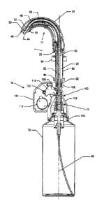
[0007] FIG. 1 is a perspective view of an automatic foam soap dispensing
system in
accordance with an embodiment of the present invention;
[0008] FIG. 2 is a cross-sectional elevation view of the system of FIG. 1;
[0009] FIG. 3 is a cross-sectional elevation view of the spout assembly of
the system of FIG.
1;
[0010] FIG. 4 is a schematic elevation view of the motor housing assembly of
the system of
FIG. 1;
[0011] FIG. 5 is a schematic perspective view showing the contact in an
actuated position
between the pump hammer of the motor housing assembly and the pump actuator of
the pump
and draw-back assembly of the system of FIG. 1;
[0012] FIG. 6 is another schematic perspective view showing the contact in
an actuated
position between the pump hammer of the motor housing assembly and the pump
actuator of the
2
SUBSTITUTE SHEET (RULE 26)
CA 02703965 2010-04-23
WO 2009/055576
PCT/US2008/080970
pump and draw-back assembly of the system of FIG. 1;
[0013] FIG. 7 is a perspective view of the draw-back assembly of the system
of FIG. 1;
[0014] FIG. 8 is an exploded view of the draw-back assembly of the system
of FIG. 1;
[0015] FIG. 9 is a cross-sectional elevation view of the draw-back assembly
of the system of
FIG. 1 attached to a liquid soap container in a non-actuated position;
[0016] FIG. 10 is a cross-sectional perspective view of the cap member of
the draw-back
assembly of the system of FIG. 1 attached to a liquid soap container;
[0017] FIG. 11 is a cross-sectional perspective view of the draw-back
assembly of the system
of FIG. 1 attached to a liquid soap container in a non-actuated position;
[0018] FIG. 12 is a cross-sectional elevation view of the draw-back
assembly of the system of
FIG. 1 in a non-actuated position; and
[0019] FIG. 13 is a cross-sectional elevation view of the draw-back
assembly of the system of
FIG. 1 in an actuated position.
DETAILED DESCRIPTION
[0020] Referring to Figs. 1 and 2, an automatic foam soap dispensing system
10 is disclosed
in accordance with one embodiment of the present invention. However, it will
be understood that
other fluid products, for example cosmetics products, personal care products,
and cleaning
products, can also be dispensed using the an automatic foam soap dispensing
system 10 without
departing from the scope of the invention. Further, it will be understood that
the automatic foam
soap dispensing system 10 is suited for dispensing other types of non-foaming
products, such as
sprays or lotions.
[0021] The foam soap dispensing system 10 generally includes three major
assemblies: a
spout assembly 12 to deliver foam soap to a user, a motor housing assembly 14
to actuate and
control the operation of the foam soap dispensing system 10, and a pump and
draw-back
assembly 16 to create foam soap and to prevent soap dripping from the spout
assembly 12
between uses.
3
SUBSTITUTE SHEET (RULE 26)
CA 02703965 2012-12-13
The Spout Assembly
[0022] Referring now to the spout assembly 12, an exemplary spout assembly is
found in
United States Patent 6,929,150 issued August 16, 2005 to Kenneth J. Muderlak
and Rocky Hsieh
and assigned to Technical Concepts, LLC =
In the embodiment of Figs. 1 and 2, the spout assembly 12 includes a
support shaft 20 which may extend through an aperture disposed through a
countertop. The
support shaft 20 may be hollow and threaded. The support shaft 20 is fixed to,
or may form a part
of, a rigid spout 24. The rigid spout 24 includes a base 25 abutting the
countertop, an upwardly
extending indicator housing portion 26, and a curved dispensing portion 28.
The outer end of the
curved dispensing portion 28 includes an indented outlet 30 having a spout
opening 32 therein to
aid in dispensing foam soap.
[0023] As shown in
Fig. 3, the curved dispensing portion 28 of the rigid spout 24 includes an
opening 34 in which an electric eye sensor or assembly 38 is mounted in the
curved dispensing
portion 28. Individual sensors, such as infrared (IR) emitter and an IR
detector, may be included
as part of electric eye assembly 38 to detect the presence of a user's hands
beneath the spout
opening 32, and, in response, to activate a switch to initiate operation of
foam soap dispensing
system 10. Indicator lights 36, for example, light emitting diodes (LEDs), may
also be disposed
behind a transparent lens 37 in the indicator housing portion 26 to signal a
"battery low" and/or
soap reservoir "empty" condition.
[0024] As shown in Figs. 2 and 3, the rigid spout 24 includes a curved
internal passageway 40
that extends from the base 25 through the spout 24 to connect with the spout
opening 32. An
elongated dispensing tube 42 is disposed in the passageway 40. When the pump
and draw-back
assembly 16 is attached to the motor housing assembly 14, the tube end 44 of
the elongated
dispensing tube 42 will move reciprocally in the passageway 40 upon actuation
of the pump and
draw-back assembly 16, as will be explained. The inner surface of the internal
passageway 40 is
composed of a smooth material to provide a substantially frictionless path for
movement of the
elongated dispensing tube 42 in the passageway 40 during installation and
removal of the pump
and draw-back assembly 16 and during each actuation of the foam soap
dispensing system 10. In
addition, the radius of curvature of the internal passageway 40 is configured
to allow the
4
CA 02703965 2010-04-23
WO 2009/055576
PCT/US2008/080970
elongated dispensing tube 42 to slidably and smoothly move inside the
passageway 40. By way
of example, in the present embodiment, the radius of curvature of the
passageway 40 is
approximately two inches. The dispensing tube 42 is made of LDPE (low density
polyethylene),
or other suitable material which will not react with the chemicals in the
soap, and which provides
a smooth outer surface to accommodate almost frictionless movement of the
dispensing tube 42
in the passageway 40.
[0025] The
indented outlet 30 may include an indented portion 31 that is set back from a
spout tip 46 of spout 24. The indented portion 31 provides a shield around the
tube end 44 of the
dispensing tube 42. The indented portion 31 may prevent the tube end 44 from
being viewed by a
user when the tube end 44 of the dispensing tube 42 extends beyond the spout
opening 32.
[0026] The
passageway 40 is centrally disposed in the spout 24 throughout the length of
the
passageway 40. As seen in Fig. 2, the lower end of the passageway 40 is
disposed along a central
or longitudinal axis 48 of a liquid soap container 70. Thus, when the
dispensing tube 42 and the
container 70 are rotated during installation of a full container 70, the
dispensing tube 42 rotates
in the passageway 40 about the axis 48 throughout the length of the passageway
40. Since the
dispensing tube 42 is centrally located about the axis 48, and is centrally
located in the
passageway 40, the container 70 is able to be rotated to be properly
positioned relative to the
motor housing assembly 14 during installation and removal of the container 70.
[0027] Referring to Figs. 2 and 3, the support shaft 20 has external threads
50 and an internal
guide passageway 52 centered around the axis 48 through which elongated
dispensing tube 42
extends. The guide passageway 52 is configured to allow the dispensing tube 42
to rotate therein
during installation and removal of the container 70 and to move reciprocally
therein in response
to the actuation of the pump and draw-back assembly 16. The external threads
50 are formed in
an outer wall of the support shaft 20 substantially along the length thereof.
A manually rotatable
nut 54 is also provided, including mating internal threads (not shown) which
engage the external
threads 50 in a known manner, permitting the nut 54 to be rotated and moved
upward to engage
the underside of a countertop and to secure the support shaft 20 and the spout
24 against
movement relative to the countertop.
[0028]
Extending from the lower portion of the support shaft 20 is a cylindrical
attachment
SUBSTITUTE SHEET (RULE 26)
CA 02703965 2010-04-23
WO 2009/055576
PCT/US2008/080970
shaft 60. The attachment shaft includes a central opening through which the
dispensing tube 42
extends along the axis 48. The attachment shaft 60 also include a plurality of
circumferentially
disposed splines 62 adapted to mate with a plurality of grooves (not shown)
circumferentially
disposed in a hollow upper interior portion 106 of the pump housing 102 of the
motor housing
assembly 14 so as to provide for the attachment of motor housing assembly 14
to the support
shaft 20. This arrangement permits the internal guide passageway 52 of the
support shaft 20 to
align with the upper interior portion 106 of the motor housing assembly 14. In
the present
embodiment, the splines 62 are disposed at thirty degree intervals.
[0029] Upon moving the motor housing assembly 14 into engagement with the
attachment
shaft 60, the circumferential distance between adjacent splines 62 and grooves
disposed in the
upper interior portion 106 of the motor housing assembly 14 allows the motor
housing assembly
14 to be rotated in thirty degree increments, allowing placement of the motor
housing assembly
14 to avoid interfering with the underside of the sink bowl and other plumbing
or structural
elements located under the countertop. This also allows the motor housing
assembly 14 to be
positioned for ease of access in case a need to service the foam soap
dispensing system 10 arises.
The Motor Housing Assembly
[0030] As
noted above, the motor housing assembly 14 provides the driving force to
actuate
the pump and draw-back assembly 16 for producing foam soap when it is
installed on the support
shaft 20. The motor housing assembly 14 may be removably attached to the lower
end of support
shaft 20 by a shank clip 64, as shown in Figs. 1 and 2. The shank clip 64 may
be generally U-
shaped and adapted to engage a circumferentially indented shaft groove 68
formed on the lower
portion of the support shaft 20 so as to secure the motor housing assembly 14
to the support shaft
20. A suitable shank clip 64 that provides easy attachment and detachment of
the motor housing
assembly 14 to the support shaft 20 is found, for example, in United States
Patent 6,929,150.
[0031] The motor housing assembly 14 includes a pump housing 102 and a motor
and
actuator mechanism housing 104, as shown in Figs. 1 and 2. The pump housing
102 includes a
hollow upper interior portion 106 that receives the attachment shaft 60, as
described above. The
pump housing 102 also includes a hollow lower interior portion 108 centered
along the axis 48
6
SUBSTITUTE SHEET (RULE 26)
CA 02703965 2010-04-23
WO 2009/055576
PCT/US2008/080970
through which foam soap may be conveyed from the pump assembly 16 to the spout
24, as will
be explained. A reservoir assembly mounting clip 110 is located at the bottom
of pump housing
102 to removably mount the reservoir and pump assembly 16 to the pump housing
102. In
particular, the mounting clip 110 is adapted to releasably and securely hold
the liquid soap
container 70 to the lower end of the pump housing 102. A suitable mounting
clip 110 is found,
for example, in United States Patent 6,929,150.
[00321 As may be seen in Figs. 2 and 4, the motor and actuator mechanism
housing 104 may
include a motor 112, gear reduction train 114 and pump hammer 116. A switch
control circuit
(not shown) may be electrically connected to the electric eye assembly 38 and
the motor 112 to
initiate operation of the foam soap dispensing system 10 and control the
operation of the motor
112 when the electric eye assembly 38 detects the presence of a user. A
suitable switch control
circuit is found in, for example, United States Patent 6,929,150. It will be
understood by one of
skill in the art that the foam soap dispensing system 10 may also include a
battery pack (not
shown) for supplying power to the motor 112 and the electronic components of
electric eye
assembly 38, and that the battery pack may be permanently or removably
connected to the motor
and actuator mechanism housing 104.
[00331 The
gear reduction train 114 is mounted for rotation in the housing 104 and
operatively connects the output of the motor 112 to the pump hammer 116. The
pump hammer
116 includes an actuate gear portion 118 which meshes with a spur gear 120,
which in turn is
driven by the motor 112 through the gear reduction train 114. The pump hammer
116 is mounted
on a pin 122 for rotation through a small arc relative to the housing 104, as
shown in Fig. 5. At
an end of the pump hammer 116 may be a pair of actuator arms 124 which rotate
as pump
hammer 116 rotates through a small arc. The pump hammer 116 also includes a
flat face 126
adapted to engage a hammer kick back stop 128, which may be rigidly, but
adjustably, mounted
on the interior of housing 104. Alternatively, the hammer kick back stop 128
may be adjustably
mounted on the housing 104. The pump housing 102 is provided with an opening
130 in one
sidewall to allow selective contact between pump hammer 116 and a pump
actuator 330 of the
pump and draw-back assembly 16, as will be explained.
7
SUBSTITUTE SHEET (RULE 26)
CA 02703965 2010-04-23
WO 2009/055576
PCT/US2008/080970
The Pump and Draw-back Assembly
[0034] Reference now will be made to the pump and draw-back assembly 16, as
shown in
Figs. 7-13. The pump and draw-back assembly 16 may include the dispensing tube
42, a pump
mechanism 200, and a draw-back mechanism 300 connected between the dispensing
tube 42 and
the pump mechanism 200 to draw in foam soap from the dispensing tube 42 after
a dose of foam
soap has been dispensed so as to prevent soap from dripping from the end 44 of
the dispensing
tube 42 between uses.
[0035]
Preferably, the dispensing tube 42, the pump mechanism 200 and the draw-back
mechanism 300 are all aligned on a common centerline along the axis 48, as
shown in Fig. 9, to
provide ease of installation of the pump and draw-back assembly 16. Thus, when
the pump and
draw-back assembly 16 is rotated during installation and removal from the
motor housing
assembly 14, all of the elements comprising the pump and draw-back assembly 16
can rotate
smoothly and substantially frictionless in their respective housings and
passageways. In addition,
the single centerline construction of the pump and draw-back assembly 16
allows the draw-back
mechanism 300 to be used with a commonly available pump mechanism 200, without
the need
for any specially constructed or located pump assemblies. This obviously
reduces the cost of the
pump and draw-back assembly 16. Further, the pump and draw-back assembly 16
may form a
unitary assembly that may be discarded when the container 70 has been emptied
of liquid soap.
Therefore, a replacement pump and draw-back assembly 16 may be furnished with
each refill
container 70 installed in the dispenser 10.
[0036] The
draw-back mechanism 300 is disposed in the hollow interior portion 108 of the
pump housing 102, as shown in Fig. 2, and is centered around the axis 48. As
shown in Figs. 7-8,
the draw-back mechanism 300 includes a cap member 302, a pump actuator 330,
bayonette guide
340, a compression spring 352, and a seal 354, which are disposed around the
axis 48 concentric
with each other.
[0037] Referring to Figs. 9 and 10, the cap member 302 is secured over the
neck 72 of the
container 70. The neck 72 of the container 70 is received in a shallow cavity
306 defined by the
lower end of the base 304 of the cap member 302. A protruding edge 308 is
formed
circumferentially around the interior surface of the cavity 306 so as to mate
with a neck groove
8
SUBSTITUTE SHEET (RULE 26)
CA 02703965 2010-04-23
WO 2009/055576
PCT/US2008/080970
74 circumscribing the neck 72 of the container 70 for securing the cap member
302 to the
container 70.
[0038] The
body 310 of the cap member 302 has a double wall construction, including a
pair
of cylindrical inner and outer walls 312, 314 that define a cylindrical
central opening 316 and an
annular opening 318 concentric with the central opening 316. The inner wall
312 has a
circumferential stop lip 320 extending radially outward therefrom at its lower
end and an annular
seat flange 322 extending radially inward therefrom at its upper end. The
annular seat flange 322
defines a seat portion 324. The outer wall 314 is concentric with the inner
wall 312 so as to
define the annular opening 318 therebetween. The upper end of the outer wall
314 extends out
past the upper end of the inner wall 312. A plurality of spaced apart stop
members 326 extending
radially inward are formed around the perimeter of the upper end of the outer
wall 314.
[0039]
Referring to Figs. 9 and 11, the draw-back assembly also includes a pump
actuator
330. The pump actuator 330 has a cylindrical body 332 and a reduced diameter
neck portion 334
that is concentric with the cylindrical body 332. The cylindrical body 332 and
the reduced
diameter neck portion 334 are joined by an annular actuator flange 336
extending radially inward
from the cylindrical body 332 at its upper end.
[0040] The
cylindrical body 332 defines an interior cavity 333. An internal cylindrical
projection 337 formed on the annular actuator flange 336 extends axially
therefrom into the
interior cavity 333 and defines a recess 339 therein. The body 332 is mounted
over the cap
member 302 concentric with the inner wall 312 of the cap member 302. A guide
flange 338
disposed about the lower end of the body of the pump actuator 330 is slidably
received within the
annular opening 318 of the cap member 302. In this way, the pump actuator 330
is moveably
connected to the cap member 302.
[0041] The pump actuator 330 moves downward when pump mechanism 200 is
actuated, as
will be explained. Downward movement of the pump actuator 330 within the
annular opening
318 of the cap member 302 is limited by the abutment of the guide flange 338
against the
circumferential stop lip 320 of the inner wall 312 of the cap member 302.
Upward movement of
the pump actuator 330 within the annular opening 318 of the cap member 302 is
limited by the
abutment of the guide flange 338 against the spaced apart stop members 326 of
the outer wall
9
SUBSTITUTE SHEET (RULE 26)
CA 02703965 2010-04-23
WO 2009/055576
PCT/US2008/080970
314 of the cap member 302.
[0042] The
reduced diameter neck portion 334 defines an axial opening 335 extending
therethrough for receiving the elongated dispensing tube 42. Elongated
dispensing tube 42 is
firmly lodged in cylindrical opening 335 of actuator 330, whereby dispensing
tube 42 moves in
reciprocal directions within guide passageway 52 along with the movement of
actuator 330.
[0043] The draw-back mechanism 300 further includes a bayonette guide 340
having a
generally cylindrical construction and an axial bore 341 extending
therethrough to allow passage
of soap from the pump mechanism 200 through the draw-back mechanism 300 and
into
dispensing tube 42, as will be explained. The bayonette guide 340 includes a
cylindrical base
portion 342, a cylindrical core portion 344 of reduced diameter joined to the
base portion 342 by
a first step portion 343, and a cylindrical tip portion 346 of further reduced
diameter joined to the
core 344 by a second step portion 345.
[0044] The
tip portion 346 of the bayonette guide 340 is mounted in the recess 339
defined by
the cylindrical projection 337 of the pump actuator 330 such that the second
step portion 345
abuts the lower end of the cylindrical projection 337 and the core portion 344
is centrally
disposed in the interior cavity 333 of the cylindrical body 332 of the pump
actuator 330. As a
result of this interface between the second step portion 345 and the lower end
of the cylindrical
projection 337, the pump actuator 330 can drive the bayonette guide 340
downward to actuate
the pump mechanism 200, as will be explained.
[0045] The
core portion 344 the bayonette guide 340 and the cylindrical body 332 of the
pump actuator 330 define a dedicated draw-back chamber 350 therebetween to
draw back foam
soap from the dispensing tube 42 after a dose of foam soap has been dispensed,
as will be
explained. The draw-back chamber 350 is concentric with the axial bore 341
extending through
the bayonette guide 340 and is disposed around and in line with the fluid path
between the
dispensing tube 42 and the pump mechanism 200. The core portion 344 of the
bayonette guide
340 has a pair of ports 348 formed opposite each other in a sidewall thereof.
The ports 348 form
fluid passageways between the axial bore 341 of the bayonette guide 340 and
the draw-back
chamber 350.
[0046] The
bayonette guide 340 is further dimensioned such that, when the pump actuator
SUBSTITUTE SHEET (RULE 26)
CA 02703965 2010-04-23
WO 2009/055576
PCT/US2008/080970
330 is mounted over the cap member 302 and is fully retracted with the guide
flange 338 in
abutment against the spaced apart stop members 326, the first step portion 343
abuts the
underside of the annular seat flange 322 of the cap member 302 and the base
portion 342 is
slidably received in the cylindrical central opening 316 of the cap member
302. The base portion
342 of the bayonette guide 340 is connected to the pump mechanism 200 so as
actuate the pump
mechanism 200, as will be explained.
[0047] The
draw-back assembly also includes a seal 354 seated in the seat portion 324
defined by the annular seat flange 322 of the cap member 302 and a compression
spring 352
mounted over the core and tip portions 344, 346 of the bayonette guide 340.
One end of the
spring 352 presses against the underside of the actuator flange 336. The other
end of the spring
352 presses against the seal 354. In this way, the spring 352 biases the pump
actuator 330 away
from the cap member 302 and the neck 72 of the container 70. When the spring
352 is unloaded
and/or fully extended in its uncompressed state, the pump actuator 330 is in
its fully retracted
and/or non-actuated position with the guide flange 338 in abutment against the
spaced apart stop
members 326.
[0048] The pump mechanism 200 is configured to deliver a predetermined dosage
of foam
soap from tube end 44 of dispensing tube 42 upon each actuation of the motor
112. The pump
mechanism 200 may include a standard, self-priming pump as is known in the art
for creating
foam soap from liquid soap without the use of gas propellants. An example of
such a foam pump
is found in a commercial foam pump supplied by Rexam Airspray Inc. of Pompano
Beach, Fla.,
USA and identified as Model F2L9. Preferably, the pump mechanism 200 generally
includes a
pump chamber 202, a pump piston 204 slidably disposed in the pump chamber 202,
and a hollow
nozzle insert 206 securely attached to the upper end of the pump piston and
adapted to provide a
sealed, internal fluid passageway between the pump mechanism 200 to the draw-
back
mechanism 300, as shown in Figs. 8 and 9. Also, the lower end of the pump
mechanism 200 may
include a cylindrical boss 210 having a hollow central portion, into which a
suction tube 208 is
inserted. The suction 208 extends downward from boss 210 to substantially the
bottom of the
liquid soap container 70, leaving a space to allow soap to be conveyed from
the bottom of the
container 70 into tube 208.
11
SUBSTITUTE SHEET (RULE 26)
CA 02703965 2010-04-23
WO 2009/055576
PCT/US2008/080970
[0049] The
container 70 includes neck portion 72 having an opening therein centered
around
the axis 48 through which the pump mechanism 200 is inserted. The pump
mechanism 200 is
mounted to the neck 72 of the container 70 in such a manner that soap can only
flow to the draw-
back mechanism 300 through the pump mechanism 200. In the present embodiment,
the upper
end of the pump chamber 202 includes a protruding, circular outer edge 212
that rests on the
upper end surface of the neck 72 of the container 70. Upon mounting the cap
member 302 of the
draw-back mechanism 300 over the neck 72 of the container 70, the outer edge
212 of the pump
chamber 202 is clamped between the cap member 302 and the neck 72 of the
container 70.
[0050] When the pump mechanism 200 is mounted to the neck 72 of the container
70, the
pump chamber 202, the pump piston 204 and the hollow nozzle insert 206 are
centered around
the axis 48 and are concentric with the bayonette guide 340 of the draw-back
mechanism 300.
The nozzle insert 206 is received in the axial bore 341 of the base portion
342 of the bayonette
guide 340 in abutment against the first step portion 343 joining the base
portion 342 and the
cylindrical core portion 344. Further, the pump piston 204 may be secured to
the base portion
342 of the bayonette guide 340 in a known manner. For example, the base
portion 342 may have
a groove circumferentially disposed within the axial bore 341 so as to firmly
engage a
circumferential thread disposed on the outer surface of the pump piston 204.
[0051] The pump mechanism 200 may be actuated by pushing the nozzle insert 206
inwardly
toward the pump chamber 202. During the compression stroke, the nozzle insert
206 drives the
pump piston 204 into the pump chamber 202 so as to create foam soap by mixing
liquid soap and
air and to pump the foam soap out through the nozzle insert 206. The pump
mechanism 200 is
spring biased so as to return to its rest state when the nozzle insert 206 is
released. During the
return stroke, the pump mechanism 200 draws in ambient air from the outside
and liquid soap
from the container 70 via a suction tube 208. It is contemplated that
additional pump
mechanisms may be used in the invention, having structure and operation that
may vary from the
pump description set forth above.
[0052] As
noted above, the motor housing assembly 14 provides the driving force for the
operation of pump mechanism 200. When the foam soap dispensing system 10 is
fully
assembled, the motor 112 rotates the actuator arms 124 of the pump hammer 116
to engage the
12
SUBSTITUTE SHEET (RULE 26)
CA 02703965 2010-04-23
WO 2009/055576
PCT/US2008/080970
actuator flange 336 of the pump actuator 330 so as to drive down the pump
actuator 330. The
pump actuator 330, in turn, drives down nozzle insert 206 to actuate the pump
mechanism 200,
as explained above.
[0053] When
the motor 112 is not energized, the pump hammer 116 is in its full kick back
position. The actuator arms 124 of the pump hammer 116 may rest on the upper
surface of
actuator flange 336, which is in its fully retracted and/or non-actuated
position. Alternatively, the
actuator arms 124 may be disposed a short distance above the upper surface of
actuator flange
336. The actuator arms 124 straddle the reduced diameter neck portion 334 of
the pump actuator
330, which extends into the open space 172 of the pump hammer 116.
[0054] Upon
actuation of the motor 112, the gear reduction train 114 drives the spur gear
120
which, in turn, rotates the pump hammer 116 clockwise, as shown in Figs. 5 and
6. As the pump
hammer 116 pivots clockwise around pivot pin 122 under the influence of motor
112, the
actuator arms 166 engage the actuator flange 336 to drive the pump actuator
330 axially
downward into the annular opening 318 of the cap member 302. The pump actuator
330 in turn
drives the bayonette guide 340 downward to actuate the pump mechanism 200 by
pushing the
nozzle insert 206 downwardly toward the pump chamber 202 for dispensing foam
soap.
[0055] During
the down stroke of the pump actuator 330, the seal 354 seated in the seat
portion 324 defined by the annular seat flange 322 of the cap member 302
remains stationary.
Therefore, as the pump actuator 330 is driven downward into the annular
opening 318 of the cap
member 302, the draw-back chamber 350 collapses and the compression spring 352
mounted
over the bayonette guide 340 is compressed. In this way, residual soap
material present in the
draw-back chamber 350 may be forced out into the fluid path through the ports
348 between the
axial bore 341 of the bayonette guide 340 and the draw-back chamber 350 to be
dispensed with
the main dose of foam soap being dispensed by the pump mechanism 200 down the
dispensing
tube 42.
[0056] The amount of downward movement of pump actuator 330 generally
determines the
amount of foam soap that is dispensed from dispensing tube 42 at tube end 44
upon each
actuation of the automatic soap dispenser 10. The distance of the downward
movement of the
pump actuator 330 is controlled by the position of hammer kick back stop 128.
To dispense a
13
SUBSTITUTE SHEET (RULE 26)
CA 02703965 2010-04-23
WO 2009/055576
PCT/US2008/080970
desired dosage of the foam soap, flat face 126 of pump hammer 116 abuts kick
back stop 128,
thus halting further clockwise rotation of pump hammer 116.
[0057]
Referring to Fig. 4, when the flat face 126 of the pump hammer 116 abuts
hammer
kick back stop 128, the motor 112 stalls and the current through the motor 112
increases. The
increase in current through the stalled motor 112 is detected by circuitry
(not shown), and the
motor 112 is shut off, thus preventing the delivery of torque by the motor 112
to the pump
hammer 116.
100581 With
the motor 112 shut off, the compression spring 352 urges the pump actuator 330
upwardly to its fully retracted and/or non-actuated position, whereby the
flange 336 of the pump
actuator 330 moves upward to force the pump hammer 116 to rotate
counterclockwise back to its
start position. Also, the pump is allowed to return to its rest state, whereby
an internal spring in
the pump mechanism 200 biases the pump piston 204 and the nozzle insert 206
upwardly,
thereby urging the bayonette guide 340 to follow the pump actuator 330 until
the second step
portion 345 abuts the lower end of the cylindrical projection 337 of the
cylindrical body 332 and
the first step portion 343 abuts the underside of the annular seat flange 322
of the cap member
302. In this way, the draw back chamber 350 expands during the return stroke,
thereby creating a
vacuum effect and drawing in foam soap from the dispensing tube 42 through the
ports 348. As a
result, foam soap is prevented from hanging at the end 44 of the dispensing
tube 42 and dripping
after a dose of foam soap has been dispensed.
Method of Operation
[0059] Once
properly installed, operation of the foam soap dispensing system 10 is
initiated
by a user inserting his or her hands under the indented outlet 30 of the spout
24. The electric eye
assembly 38 detects the presence of the hands, and sends a signal to actuate
the motor 112. The
gear reduction train 114 drives the pump hammer 116 in a clockwise direction,
as viewed in
Figs. 2 and 6, whereby the actuator arms 124 positively engage the actuator
flange 336 of the
pump actuator 330 and drive the pump actuator 330 downward a predetermine
distance. The
downward movement of pump actuator 330 causes elongated dispensing tube 42 to
withdraw the
same distance into spout 24 and passageway 40. Preferably the tube end 44 of
dispensing tube 42
14
SUBSTITUTE SHEET (RULE 26)
CA 02703965 2010-04-23
WO 2009/055576
PCT/US2008/080970
remains outside of the spout opening 32 in spout 24 in the withdrawn position.
[0060] As the pump actuator 330 moves downward from its fully retracted and/or
non-
actuated position (see Fig. 12) under the influence of the pump hammer 116, a
measured dosage
of foam soap is dispensed from the tube end 44 of the dispensing tube 42, even
as the dispensing
tube 42 is pulled to its withdrawn position by the pump actuator 330.
According to one
embodiment, the pump mechanism 200 includes a self-priming pump that is filled
with liquid
soap prior to actuation of the pump mechanism 200. As pump actuator 330 moves
downward,
pump mechanism 200 creates foam soap by mixing liquid soap and air and expels
the foam soap
into the dispensing tube 42 through the bayonette guide 340. Also, the draw-
back chamber 350
collapses, as shown in Fig. 13, forcing out residual soap material into the
dispensing tube 42
through the ports 348 in the bayonette guide 340 to be dispensed with the main
dose of foam
soap from the pump mechanism 200.
[0061] As
pump hammer 116 reaches its limit of clockwise rotation, the motor 112 stalls
and
is shut off. When the motor 112 is shut off, the pump mechanism 200 is spring
biased to return to
its rest state. Also, the compression spring 352 urges the pump actuator 330
upwardly to its fully
retracted position, forcing the pump hammer 116 to rotate counterclockwise
back to its start
position and the dispensing tube 42 to move upward back out of the spout
opening 32 in the
spout 24. As the pump actuator 330 moves upward, the draw-back chamber 350
expands, as
shown in Fig. 12, to create a vacuum effect drawing foam soap from the
dispensing tube 42 into
the draw-back chamber 350 through the ports 348 of the bayonette guide 340. In
this way, the
draw-back mechanism 330 prevents foam soap hanging and dripping from the tube
end 44 of the
dispensing tube 42 between uses.
[0062] Various embodiments of the invention have been described and
illustrated. However,
the description and illustrations are by way of example only. Other
embodiments and
implementations are possible within the scope of the invention and will be
apparent to those of
ordinary skill in the art. Therefore, the invention is not limited to the
specific details of the
representative embodiments, and illustrated examples in this description.
Accordingly, the
invention is not to be restricted except as necessitated by the accompanying
claims and their
equivalents.
SUBSTITUTE SHEET (RULE 26)