Note: Descriptions are shown in the official language in which they were submitted.
CA 02704146 2010-04-29
WO 2009/056896 PCT/HU2008/000128
Wind turbine with vertical axis and wind power plant
Technical field of the invention
The invention relates to a wind turbine with vertical axis, and a wind power
plant.
Background art
A rising number of solutions having specific embodiments and performance being
disclosed in the art, which intend to exploit and convert the energy of the
streaming air
into other type of energy. In fact it is intended to convert into electric or
other type of
energy - the most widely known systems are for example those used for pumping
or
heating water.
In the framework of the alternative energy programs the more effective
exploitation
of the wind energy becomes more and more considerable worldwide. The wind
turbines
having horizontal axis are the most widely spread constructions primarily in
the case of a
great performance demand; constructions having three blades are most
frequently used,
operation of which is well known in the art.
A disadvantage of the latter is that its effective operation may be achieved
in great
heights only, due to the highest speed of the wind in these levels.
Further, disadvantage is due to a feature involving a constant need to
orientate the
plane of the blades always perpendicularly to the velocity vector of the wind
and to
change the angle of blades, in order to obtain the optimal and effective
energy producing
level.
Such a multidirectional movement makes great demands upon the system, that is
the adequate technical requirements can be met by very expensive solutions
only.
A further disadvantage of such a wind turbine system is that its construction
requires a high quantity of materials to be located at great heights as well.
Wind turbines with horizontal axis can exploit the energy to be converted in a
surface defined by its plane of blades only.
Furthermore, these systems can exploit the wind energy effectively in a narrow
range of wind speed only.
To overcome these disadvantages of the systems with horizontal axis many
solutions have been proposed in the art using wind turbines with vertical
axis.
Such type of solutions is disclosed for example in the patent documents
US4365.929, US 6749393, US2005079054, DE4122919, JP2006037898 and
CA 02704146 2010-04-29
WO 2009/056896 PCT/HU2008/000128
2
DE102005041600. Common disadvantage of these solution is that their
construction is
very complicated and expensive.
The main aspect of the present invention is to provide a wind turbine having
vertical axis on the basis of the theoretical solutions of a new mathematical
concept
relating to the energetic system of fluid mechanics.
Therefore, the object of the present invention is to provide a wind power
plant
operating always in the same manner, in contrast with the prior art plants,
without a feed-
back regulation and independently of actual wind direction, and having a
minimum flow
resistance - that is having a high effectiveness - due to a balance between
the torques
affected on the inlet and outlet sides of the plant and to its novel
geometrical
configuration, and having a simple construction and a low cost of maintenance,
and
further having an ability to work effectively even in weak wind circumstances
and sites,
and being insusceptible to both sudden changes and distribution of wind load
as a
function of height.
Disclosure of the invention
The object of the present invention is achieved by providing a wind turbine
with
vertical axis, having a rotor and a generator connected with said `axis, and a
supporting
structure holding the axis of said rotor by means of bearings, and said rotor
consists of an
axis fitted with an upper bearing mounted in an upper part of an upper console
and with a
lower bearing mounted in a building formed along the ground level, and
supporting rings
perpendicularly attached to the axis spaced apart along said axis, and a
plurality of
arcuate beams fitted with said rings and supporting turbine blades, and
wherein there is a
wind passage formed between edges placed on the inner diameter of the adjacent
blades, and said passage having a size depending on the geometrical
configuration of the
turbine blades and that of the baffle means surrounding said rotor.
The wind turbine according to the invention preferably has at least two
arcuate
beams, and said turbine blades are formed as a shape determined by at least
one quadric
and/or trigonometric and/or hyperbolic mathematical curve.
Furthermore, the plane of an arcuate beam is advantageously perpendicular to
the generatrices of said turbine blade, and an optional number of parting
vanes are
arranged in a plane perpendicular to the generatrices of said turbine blades.
The wind turbine preferably comprises baffle means having deflecting and
supporting elements as efficiency enhancers arranged between inner diameter
and outer
diameter thereof, the number of which is equal to the number of said baffle
means, and
said efficiency enhancers form a closed polygon, and the supporting structure
is formed
CA 02704146 2010-04-29
WO 2009/056896 PCT/HU2008/000128
3
by tubes or rolled shape pieces known in itself, and it is arranged in a
plurality of planes
perpendicular to the axis.
The wind turbine more preferably contains a supporting roller runway arranged
along said axis and between the outer diameter of the rotor (F) and the inner
diameter of
the baffle means, and the runway (G) consists of a supporting ring formed on
the baffle
means and contacted to a race ring arranged on the outer diameter of the
rotor.
Twin vanes having shorter arc length are arranged symmetrically between said
turbine blades at the outer diameter of the rotor, and its number is equal to
the number of
turbine blades, and whirl triggers delimited by four surfaces are arranged in
the same
plane as said efficiency enhancers.
The object of the present invention is achieved also by providing a wind
turbine
with vertical axis, having a rotor and a generator connected with said axis,
and it can be
built with an optional height, and floors are formed spaced apart with equal
distances
along said height, and rotors consisting of supporting rings fixed spaced
apart and having
arcuate beams supporting turbine blades are arranged between said floors, and
the axes
of rotor(s) are bearing fitted in a hole of said floor.
Said floor preferably has a shape of a cylindrical disc, or a shape of an
ellipsoid.
Said floor and said baffle means are made of light constructed armoured
concrete.
The wind turbine advantageously comprises resilient members compensating
different motions of parts of its axis, resulting in an even rotation.
Description of the drawings
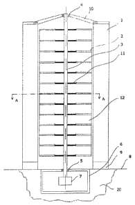
Fig. 1. is a vertical sectional view of the wind turbine with vertical axis
according to
the invention,
Fig. 2. a sectional view taken along the plane A-A of Fig . 1.,
Fig. 3. is a perspective side view of the second embodiment of the wind
turbine
with vertical axis according to the invention
Fig. 4. a sectional view taken along the plane A-A of Fig . 3.,
Fig. 5. a sectional view taken along the plane B-B of Fig . 4.,
Fig. 6. is a top side view of whirl triggers of the wind turbine with vertical
axis
according to the invention,
Fig. 7. is a perspective view of a whirl trigger showed in Fig. 6.,
Fig. 8. is a perspective side view of the third embodiment of the wind turbine
with
vertical axis according to the invention,
Fig. 9. a sectional view of the wind turbine in Fig. 8., taken along the plane
C-C,
Fig. 10. a sectional view of the wind turbine in Fig. 9., taken along the
plane D-D,
CA 02704146 2010-04-29
WO 2009/056896 PCT/HU2008/000128
4
Fig. 11. is a schematic operational diagram of the wind turbine according to
the
invention.
Detailed description of preferred embodiments
Fig 1. is a vertical sectional view of the wind turbine with vertical axis
according to
the invention, where the wind turbine is supported by the ground 8 level.
Central control
station and devices to operate the wind turbine are located in a building 20
arranged along
the ground 8 level.
A base element 9 supporting the upper machinery of the wind turbine is
arranged
on the ground 8 level, and said upper machinery is topped by an upper console
10.
The axis 3 of the wind turbine is held by a bearing 4 of the upper console 10
and a
bearing 5 fixed in the building 20, and connected to a generator 7 arranged in
the building
7 in manner known itself, so that the generator 7 is driven by the axis 3.
Baffle means 1 adapted also for vertical load bearing are placed on the base
element 9 arranged on the ground 8 level. Baffle means 1 are fixedly attached
to the base
element 9. Upper ends of the baffle means 1 are rigidly cross braced by the
upper
consoles 10.
Supporting rings 11 having a diameter d, are placed on the axis 3 held by a
bearing 4 of the upper console 10 and a bearing 5 fixed in the building 20,
preferably
spaced apart by equal distances along said axis 3 and parallelly to each
other, and their
mounting plane is perpendicular to said axis 3. (see Fig. 1. and 3.)
Arcuate beams 2 supporting and fixing turbine blades 12 are clamped to
supporting rings 11 mounted on the axis 3. (Fig. 2.)
The number of the turbine blades 12 and that of the arcuate beams 2 attached
thereto is arbitrary, but at least two are necessary.
The surface of the turbine blades 12 are formed as a shape determined by at
least
one quadric and/or trigonometric and/or hyperbolic mathematical curve.
The axis 3 with the supporting rings 11 mounted thereon and holding the
arcuate
beams 2 provided with turbine blades 12 form a single unit that is the rotor
F, and these
elements in operation rotate at the same rotational speed.
Arcuate beam 2 and supporting ring 11 provided on the axis 3 have a
construction
having a structure known itself, for example of a grid structure made of
aluminium or
plastic material.
The turbine blade 12 is arranged on the arcuate beam 2 so that its
generatrices
are adjoining the inner part of the arcuate beam 2.
CA 02704146 2010-04-29
WO 2009/056896 PCT/HU2008/000128
There is a wind passage S formed between edges placed on the inner diameter d,
of the adjacent blades 12, and said passage S has a size depending on the
geometrical
configuration of the turbine blades 12 and that of the baffle means 1
surrounding said
rotor F.
It is to be noted, that in case of high performance wind turbines an arbitrary
number of parting vanes C might be arranged in a plane perpendicular to the
generatrices
of the turbine blades 12, and said vanes C have a plane perpendicular to the
generatrices
of the blades 12.(Fig. 3.)
The diameters of each component are very important factors. Inner arcs of
baffle
means 1 start in a diameter d3 being larger than the diameter d2 of the
turbine blades 12.
Viewing perpendicularly to the generatrices of the baffle means 1 there are
located
concave and convex arcs.
The outermost points of the arcs of the baffle means 1 are arranged in a
circle
having a diameter d4.
Baffle means 1 are positioned vertically and symmetrically spaced apart with
equal
angles therebetween.
In case of a wind turbine having less performance the construction of the
baffle
means 1 is formed by a grid structure having a vertical sheet covering and its
material
can be selected optionally.
There is a strict mathematical function between the diameter d2 of the rotor F
as
well as the outer d3 and inner d4 diameters of the baffle means 1, determined
by the wind
speed and the performance rating of the wind turbine. In case of a relatively
lower wind
speed it is advantageous to choose the diameter d4 of the baffle means 1
greater and the
diameters d2 and d3 lesser, since the incoming air volume will be greater in
this case
albeit that the number of baffle means remains, and the same volume as the
incoming air
volume must enter between the turbine blades 12 having reduced diameter d2.
Because of
the equation of continuity these two volumes must be equal, a much greater
entering air
speed can be obtained at diameter d3, resulted in a kinetic energy raised in a
quadratic
ratio. One of the most advantageous effects of the present invention in
comparison of the
prior art solutions is its effective feasibility and applicability also under
low wind
circumstances.
Operation of the wind turbine according to the invention will be described
later in
details in reference of Fig. 11.
Fig 2. shows a high power embodiment of the wind turbine with vertical axis
disclosed in relation of Fig. 1. according to the invbention.
CA 02704146 2010-04-29
WO 2009/056896 PCT/HU2008/000128
6
The solution depicted in Fig. 4. contains eight baffle means 1 and efficiency
enhancers 13 - baffle and supporting means in itself as well - arranged along
a diameter
less than diameter d4 but larger than diameter d3 of the baffle means 1.
Efficiency enhancers 13 form a closed polygon according to the number of
baffle
means 1, increasing the construction's strength and efficiency.
The corners of the polygon of efficiency enhancers 13 adjoin the side surface
of
the baffle means 1 perpendicularly to the generatrices of the baffle means 1.
A preferred embodiment of the efficiency enhancer 13 is shown in Fig. 5.
Efficiency. enhancer 13 has a framework comprising tubes or section profiles
known in itself, which are attached to two adjacent baffle means 1 preferably
by means of
welded joints.
The framework of the efficiency enhancer 13 includes supporting elements a
surrounded by a casing b, where the number of supporting elements a is
preferably eight,
although this number may optionally be chosen.
Longitudinal structural elements and generatrices of casing b of the
efficiency
enhancer 13 are placed in planes being perpendicular to the shell of the
baffle means
1.(Fig. 4.)
Each supporting element a of the efficiency enhancer 13 is perpendicular to
the
baffle means 1 and is arranged parallelly to the plane of the supporting ring
11 and
arcuate beam 2, therefore it is advantageous to arrange the efficiency
enhancer 13 in the
plane of the supporting ring 11 and arcuate beam 2.
Optional number of efficiency enhancers 13 may be mounted parallelly to each
other in the baffle means 1.
The material used to build the efficiency enhancers 13 is a function of the
performance of the wind turbine, that is in case of higher demand of
performance the
efficiency enhancers 13 are made of steel reinforced concrete, like the baffle
means 1.
In this embodiment a supporting roller cam G surface can be arranged between
the outer diameter d2 of the rotor F and the inner diameter d3 of the baffle
means 1 (Fig.
3.). Supporting roller cam G surfaces provide an accurate distance control
between the
outer diameter d2 of the rotor F and the inner diameter d3 of the baffle means
1 even in
case of very long (high) rotors F and extreme wind load.
The number of supporting roller cam G surfaces to be built in along the rotor
F will
be determined by the expected load wind the and planned performance of the
wind
turbine.
In an embodiment according to Fig. 3. there are built three supporting roller
cam G
surfaces.
CA 02704146 2010-04-29
WO 2009/056896 PCT/HU2008/000128
7
A base member of the supporting roller cam G surface is a supporting ring
supported by baffle means 1 and engaging a race ring n arranged on the outer
periphery
d2 of the rotor F.
In an embodiment of a high power wind turbine shown in Fig. 6. twin vanes 16
having shorter arc length are arranged symmetrically between turbine blades
12. Arc
length of the twin vanes 16 is shorter than the arc length of the turbine
blades 12 and
outermost generatrices running parallelly to the axis 3 of this vanes 16 are
placed on the
diameter d2 of the rotor F, the number of the vanes 16 is equal to the number
of turbine
blades 12.
As mentioned above, in case of a high power wind turbine it is preferable to
apply
whirl triggers 14 on the baffle means 1 arranged perpendicularly to the axis 3
an in the
same plane as the efficiency enhancers 13.
Whirl triggers 14 of this embodiment are depicted in Fig. 7. It is clearly
shown in
the figure, that a whirl trigger 14 is a body delimited by four surfaces.
The operation of the second embodiment is substantially equal to that of the
embodiment shown in Fig 1., except that the air flow moving between the
turbine blades
is modified by the efficiency enhancers 13 and whirl triggers 14, which
results in an
increased performance.
Fig 9. depicts the structure of a wind turbine having an arbitrary
performance.
The height of a wind turbine shall be determined by the dynamic stability. In
this
embodiment at least one retaining and dividing floor 17 is formed along a
predetermined
height of the baffle means 1 in order to achieve dynamic stability, made of a
known
constructional material, preferably of a material equal to the material of the
baffle means
1. For high power wind plants, that os over 1 MW, this material is preferably
steel
reinforced concrete.
Retaining and dividing floors 17 might be arranged in an arbitrary number
perpendicularly to the baffle means I and axis 3 as well, forming a
construction being
unitary as regards both to fluid dynamics and strength mechanics, the sizes of
which is
determined substantially by the size of the axis 3 and the outer diameter d4
of the baffle
means 1.
Floors 17 are spaced apart from each other by the same distance h determining
also the length of the axis between the floors 17.
Wind turbine showed in Fig. 1. and 2. is substantially placed between two
floors 17
(see Fig. 9.), but it is possible to arrange different embodiments of wind
turbines between
two floors 17. The upper console 10 may be omitted in this case, indeed, since
its role is
taken up by floor 17.
CA 02704146 2010-04-29
WO 2009/056896 PCT/HU2008/000128
8
A floor 17 is shown in Fig. 10., having a through hole 18 in the middle and
receiving the axis 3 preferably bearing fitted in the hole 18.
The floor 17 is preferably disc shaped, and advantageously it is formed as an
ellipsoid of rotation or any other body suitable according to fluid dynamics.
In this
embodiment the height limit is determined by the length of the axis 3. For
that very reason
it is preferred to apply an axis 3 divided according to the distance h of the
floors 17, but in
this case the bearing arrangement requires a special structural construction,
as follows.
Due to the floor 17 used on this embodiment more than one sections F1, F2,
F3...Fn of the rotor F may be arranged along the overall height. Since the
wind force
affecting the turbine blades 12 arranged between two parallel floors 17 may be
different,
different air flowing circumstances must be taken into account between
different floors 17.
Having regard to this fact in planning, the axis 3 can be formed by sections
F1, F2,
F3...Fn according to distance h, so that a given section F1 shall be gear
fitted in the
central hole 18 formed in the respective upper floor 17, and the lower end of
the section
F1 shall be connected to the upper end of a lower section F2 preferably by
means of an
elastic coupling supporting the section F1 in axial direction, but allowing
only a small
lateral movement. In this embodiment, the bearing is fixed in the holes 18 by
means of a
resilient structural element. This way a flexural buckling of the axis 3
consisting of sections
F1, F2, F3...Fn might be omitted even in case of a great wind load affecting
differently
along the height of the wind turbine.
Operation of the wind turbine with vertical axis 3 according to the invention
will
now be described in reference of FIG. 11.
The principal advantage of the wind turbine with vertical axis 3 according to
the
invention is that it can be used at every wind speed and the performance of
the generator
- i.e. hot water supply - increases along with increasing wind speed, and it
has an
earthquake proof construction.
An air mass arriving to a surface determined by the diameter d4 and a
respective
height enters into the wind plant through openings f, determined by the baffle
means 1.
Entering air will be accelerated by both the curvature of the baffle means 1
and by the
cross sectional area narrowing from an opening surface f, to an opening f2
being smaller
than surface f,. The accelerated air mass having now increased speed and
having,
therefore, increased impulse enters the turbine blades 12 through opening f2,
exerts a
torque to the rotor F while receiving a change of flow direction, and flows
into the
opposite turbine blades 12 through a passage S delimited by the axis 3 and
supporting
rings 11, where its impulse shall be changed and receiving a further change of
flow
direction exerts a further torque on the turbine blades 12.
CA 02704146 2010-04-29
WO 2009/056896 PCT/HU2008/000128
9
Due to the arrangement of the system the curves and openings f, , f2 of the
baffle
means 1, as well as the diameter d2 of rotor F and curves of the turbine
blades 12 provide
a laminar flow at every speed, and the torque obtained will be equal on the
turbine blades
12 both in the inlet and outlet, therefore symmetrically exerted to the axis
3.
The openings of the baffle means 1 have an inverse behaviour at the outflow
side,
indeed, as compared to the inflow circumstances.
Spent air exiting the outflow side opening f2 expands up to the opening f,
having
greater surface, then it will be carrying away by an air flow flowing freely
beside the wind
plant, which phenomenon decreases the flow resistance and increases the
effectiveness
of the wind turbine.
The main advantage of the wind power plant according to the present invention
is
that it provides a wind power plant operating always in the same manner, in
contrast with
the prior art plants, without a feed-back regulation and independently of
actual wind
direction, and having a minimum of flow resistance - that is having a high
effectiveness -
due to a balance between the torques affected on the inlet and outlet sides of
the plant
and to its novel geometrical configuration, and has a simple construction and
a low cost
of maintenance, and further has an ability to work effectively even in weak
wind
circumstances and sites, and being insusceptible to both sudden changes and
distribution of wind load as a function of height.