Note: Descriptions are shown in the official language in which they were submitted.
CA 02704699 2010-05-04
WO 2009/061710 PCT/US2008/082315
METHOD AND APPARATUS FOR RAPIDLY COUNTING AND IDENTIFYING
BIOLOGICAL PARTICLES IN A FLOW STREAM
BACKGROUND OF THE INVENTION
1. Field of the Invention
This invention relates to flow cytometers and hematology analyzers, and,
more particularly, to hematology analyzers that count and identify biological
cells
using light scattering and fluorescence techniques in an optical flowcell.
2. Discussion of the Art
Flow cytometry is a technique for counting, examining, and sorting
microscopic particles suspended in a stream of fluid. Flow cytometry allows
simultaneous, multiparametric analysis of the physical and/or biochemical
characteristics of single cells flowing through an optical/electronic
detection
apparatus. When used in hematology analyzers, flow cytometry enables the
precise
counting of cells in a measured volume of blood or other biological fluid
sample and
the identification of those cells based on the use of light scattering and/or
fluorescence detection. As used herein, the phrase "flow cytometry" refers to
the
techniques and apparatus used in flow cytometers as well as in flow-cytometry-
based hematology analyzers and other diagnostic instruments.
In flow cytometry, a beam of light, such as, for example, laser light of a
single
wavelength, light of a broader spectral nature from a light-emitting diode
(LED), or
some other source of light, is directed onto a hydrodynamically focused stream
of a
fluid carrying particles, or onto such a stream otherwise confined. A number
of
detectors are aimed at the region where the stream passes through the light
beam,
one or more detectors being in line with the light beam and typically several
detectors positioned perpendicular to the light beam. The detector(s) in line
with the
light beam detect forward scatter, in one or more angular annuli or regions,
or optical
extinction, or both forward scatter and optical extinction. The detectors
positioned
perpendicular to the light beam detect side scatter, fluorescence, or both
side scatter
and fluorescence. Each suspended particle passing through the beam scatters
the
light in some way, and fluorescent chemicals in, or on, the particle, and
either
1
CA 02704699 2010-05-04
WO 2009/061710 PCT/US2008/082315
natively present in the particle or added to it during an incubation step, may
be
sufficiently excited to emit light at a longer wavelength than that of the
light source.
The combination of absorption, scattered light, and fluorescent light is
detected by
the detectors, and by analyzing fluctuations in intensity at each detector
(typically
one detector for each desired fluorescent emission band and one detector for
each
annulus or region of scattering angles), it is possible to determine various
facts about
the physical and biochemical structure of each individual particle. Forward
scatter
correlates with the volume of the cell and side scatter depends on the
complexity of
the particle, such as, for example, the shape of the nucleus, the amount and
type of
cytoplasmic granules or the roughness of the cellular membrane. Fluorescent
markers can be conjugated with monoclonal antibodies that selectively bind to
antigens present on certain types of cells or to cells in a particular
pathological state;
fluorescent dyes that bind selectively to nucleic acids in either the
cytoplasm, cellular
nucleus, or both, may also be employed. Representative examples of instruments
employing flow cytometers are described in United States Patent Nos.
5,017,497;
5,138,181; 5,350,695; 5,812,419; 5,939,326; 6,579,685; 6,618,143; and United
States Patent Publication No. 2003/0143117 Al. These documents describe a
flowing stream of cells and a stationary beam.
A subfield of cytometry, laser scanning cytometry (LSC), involves scanning a
laser beam across a field of interrogation. However, the field of
interrogation is
stationary, typically a section of a microscope slide to which cells have been
adhered, and the measurement rate (i.e., the number of cells analyzed in a
given
unit of time) obtainable through such a scheme is far below what can be
obtained by
conventional flow cytometry. Furthermore, LSC is an imaging method suitable
for
detailed analysis of a relatively limited number of cells, whereas flow
cytometry is a
light-scattering and fluorescence-tagging method of analyzing large quantities
of
cells. See, for example, United States Patent Nos. 5,072,382, 5,523,207, and
6,002,788. Two other techniques closely related to LSC are volumetric
capillary
cytometry (see, for example, United States Patent No. 5,962,238 and European
Patent No. 0681/78) and microvolume LSC (see, for example, United States
Patent
Nos. 6,603,537 and 6,687,395, and United States Patent Publication No.
2005/0280817). All of these techniques rely on a scanning laser beam impinging
upon a specimen fixed to a controllable stage and on methods based on highly
resolved imaging, confocal scanning, or spectroscopy techniques.
2
CA 02704699 2010-05-04
WO 2009/061710 PCT/US2008/082315
Several teachings in the prior art describe an imaging flow cytometer that
combines the flow characteristics of a conventional analyzer with imaging
capabilities. See, for example, United States Patent Nos. 5,083,014,
5,444,527,
5,521,699, 5,644,388, 5,824,269, 6,671,044, and 6,975,400, and United States
Patent Publication Nos. 2002/0146734 and 2002/0057432. In the prior art, (a)
the
laser or other light source is stationary, necessitating the use of a charge-
coupled
detector (CCD) array in order to capture information from across the field of
interrogation; and (b) the information obtained is of an imaging nature rather
than of
a scattering nature. This approach causes the process to run significantly
more
slowly than in flow cytometry; in other words, in order to obtain more
detailed
information for each cell by the use of the disclosed imaging strategy, the
measurement rate is reduced, i.e., the overall number of cells actually
analyzed in a
given unit of time is reduced.
One of the key advantages of imaging methods is that such methods are
capable of capturing fine details of individual cells, which enable a trained
professional to make positive identifications in borderline cases. However,
the
greater detail obtainable by imaging methods are balanced by the reduction in
the
total number of cells that can be analyzed in this way in a given period of
time. In
methods based on scattering, identification is based on characteristics that
are
averaged over the cell (such as cell size, hemoglobin content, lobularity of
the
nucleus, etc.); however, the loss of fine detail in individual cells is
compensated for
by the ability to collect desired information for tens of thousands of cells
in a matter
of seconds. Such information can be used to plot the results in aggregate
according
to a few characteristics (such as, for example, size, lobularity, etc.).
The CELL-DYN Sapphire hematology analyzer (commercially available
from Abbott Laboratories), an instrument based in part on flow cytometry,
processes
a minimum of 105 complete blood count (CBC) samples per hour under standard
conditions. This aspect of performance is referred to as the throughput of the
instrument. Other commercially available hematology analyzers are capable of
processing up to 150 standard CBC samples per hour, although the performance
tradeoffs adopted in their designs usually result in higher rates of reflex
testing, slide
review, or both reflex testing and slide review. It would be desirable to
increase the
effective throughput of hematology analyzers (i.e., accounting for both the
mechanical throughput and the rate of first-pass reportability) so as to be
able to
3
CA 02704699 2010-05-04
WO 2009/061710 PCT/US2008/082315
process a higher volume of standard CBC samples per hour than currently
possible,
while at the same time maintaining a low rate of reflex testing and slide
review. This
improvement would enable use of such an analyzer in a high-volume laboratory
(reference laboratory or hospital core laboratory), which requires the
processing of
large numbers of standard, mainly normal, CBC samples per day with as few
slide
reviews as possible. It would also enable higher throughput of samples in any
of the
other laboratory environments where an analyzer is used.
There are several obstacles to higher throughput, such as, for example,
loading samples, aspirating samples, dispensing samples, diluting samples,
mixing
samples, incubating samples, staging samples, delivering samples to the
flowcell,
and the time required for a sequential measurement of a series of samples.
These
obstacles can be thought of as bottlenecks, where the narrowest bottleneck
determines the overall throughput of the instrument. The current narrowest
bottleneck in the CELL-DYN Sapphire instrument is the time involved in the
sequential measurements through the optical flowcell. The performance
currently
achieved involves a compromise between acceptable levels of coincidences,
acceptable precision of results (total number of cells counted), constraints
from the
present hardware/electronics architecture, i.e., arrangement of hardware and
electronic components, and constraints from the assay strategy involving
reagents
and dilution. As used herein, a "coincidence" is interpreted to mean an event
where
two or more cells, either of a similar type or a dissimilar type, are
sufficiently close
that they cannot be resolved by the instrument, are counted as one, and are
misidentified in one or more detection parameters.
Increasing the flow rate through the flowcell by widening the sample stream,
by increasing the velocity of the sample stream, or both of the foregoing,
have all
been attempted. In a conventional flow cytometer, where the sample stream is
intersected by a stationary beam, the measurement rate in the linear regime
(defined
as the number of cells being analyzed per second, n) is given by
n = PXstreamZstreamVstream5 (Eq. 1)
where p represents the concentration of cells in the sample stream, .xstream
represents
the transverse dimension of the illuminated portion of the sample stream,
Zstream
4
CA 02704699 2010-05-04
WO 2009/061710 PCT/US2008/082315
represents the longitudinal dimension of the illuminated portion of the sample
stream, and vstream represents the flow velocity. In order to increase the
measurement
rate, one can attempt to increase any one of those four quantities. However,
under
the circumstances encountered in the state of the art, increasing p leads to
greater
coincidence events, as does increasing Xstream and Zstream. Increasing Vstream
can lead
to risks related to the onset of turbulence or other kind of hydrodynamic
instability,
which can severely reduce the precision of the measurements, because the
resulting
sample stream oscillates or fluctuates unpredictably across a stationary light
beam.
Other options include simply doubling the entire measurement hardware, with
two sets of measurements occurring in parallel on separate flowcells
interrogated by
separate sources of light. Two sources of light can be employed or a single
source
of light can be split into two. The shortcomings of this approach are
increased
complexity, a greatly increased cost, a greatly increased risk to reliability
because of
the large number of additional components, and increased service costs.
United States Patent Application Serial No. 11/934,277, incorporated in full
herein by reference, addresses satisfactorily the issues described above,
namely
improving the throughput of a flow cytometer without incurring higher
coincidences,
without degrading precision of results, without greatly changing the hardware
and/or
electronics (and consequently having to meet most of the same constraints),
without
necessarily changing the chemistries and dilutions currently in use, and while
maintaining the currently available desirable attributes associated with a
high rate of
first-pass reportability of results. That disclosure describes a method and
apparatus
capable of achieving a significant improvement in performance with relatively
limited
changes in the architecture and operation of a current analyzer. While such
limited
scope of design changes is attractive and beneficial from a commercial
viewpoint, it
also constrains the degree to which the innovations described in the
concurrent
disclosure can be exploited.
In hematological assays aimed at determining parameters from human whole
blood, there are two physiological factors that present obstacles to simple,
rapid, and
accurate determination of cell counts. One factor is that, in typical fresh
peripheral
human whole blood, there are about 1,000 red blood cells (RBCs) and about 50
platelets for each white blood cell (WBC). The other factor is that, while
platelets are
typically sufficiently smaller than any other cell type to allow
discrimination based on
CA 02704699 2010-05-04
WO 2009/061710 PCT/US2008/082315
size, and most white blood cells (WBCs) are sufficiently larger than either
RBCs or
platelets to again allow discrimination based on size, two cell species in
particular -
RBCs and lymphocytes, a subtype of WBCs - typically overlap in size
distribution (as
well as in their scattering signatures) to a sufficient degree to make
discrimination
based on size prone to gross error. Therefore, when determining RBCs mainly by
size discrimination, the asymmetry in concentration works in one's favor,
since the
occasional WBC misclassified as a RBC will not, generally, affect the overall
accuracy of the measured concentration of RBCs to any appreciable degree;
however, the converse is not true, and any unaccounted for interference from
RBCs
in determining the concentration of lymphocytes (and, by extension, the
overall
concentration of WBCs) would yield very inaccurate results.
Consequently, methods have been developed in the prior art to handle this
large asymmetry and size overlap and still provide useful results in an
acceptable
time frame. One standard method employed in the prior art has been to separate
the blood sample to be analyzed into at least two aliquots, one destined for
RBC and
platetet analysis, and one for WBC analysis. The aliquot destined for WBC
analysis
is mixed with a reagent solution containing a lysing reagent that
preferentially attacks
the membranes of the RBCs. Partially on account of their loss of hemoglobin
through the compromised membrane, and partially on account of their attendant
reduction in size, the resulting lysed RBCs become distinguishable from
lymphocytes
based on their respective scattering signatures. Another method employed in
the
prior art involves using nucleic acid dyes to provide a fluorescent
distinction between
the RBCs and the WBCs. WBCs contain a nucleus containing DNA. When these
WBCs are labeled via a fluorescent label, they can be distinguished from
mature
RBCs, whose nuclei have been expelled in the maturation process.
Both of these methods have drawbacks. First of all, the lysing reagent used to
dissolve the RBCs can attack the WBCs as well, reducing their integrity and
eventually dissolving them, too. This is particularly a problem with WBCs that
are
already fragile in the first place, due to some pathological condition (such,
as, for
example, chronic lymphocytic leukemia). At the other end are types of RBCs
(such
as, for example, those found in neonates, and in patients with thalassemia,
sickle-
cell anemia, and liver disease) which are naturally resistant to lysis, and
which
therefore tend to persist as interferents in WBC assays involving lysis. In
order to
reduce the likelihood of either degradation of WBCs or interference from
unlysed
6
CA 02704699 2010-05-04
WO 2009/061710 PCT/US2008/082315
RBCs (either of which would jeopardize the accuracy of the overall WBC
concentration measurement), a careful combination of concentration of lysing
agent,
temperature control, and incubation time must be used. In some cases, the user
is
offered several test options with different lysing conditions, thereby
allowing the user
to tailor the assay to the subject patient sample. This tailoring, however, is
a
complex solution, which additionally either requires prior knowledge of the
state of
the patient, or must be used as a reflex test following a standard CBC.
Regarding the fluorescence-based approach at discriminating between RBCs
and lymphocytes, the main obstacle is the measurement rate. When WBCs are
measured at the same time as RBCs and platelets, the presence of RBCs sets an
upper limit to the concentration that can be sent through the analyzer without
incurring in coincidences at an unacceptably high rate; the dilution ratio
used to
achieve such concentration, in turn, limits the rate at which WBCs events are
being
counted; and in order to obtain the counting precision expected of the
analyzer, this
relatively low rate of WBC event acquisition, in turn, forces long acquisition
times.
For example, the concept of measuring all of the components of blood from a
single
sample in one pass was disclosed in United States Patent No. 6,524,858. As
noted
in that disclosure, the method would be capable of a cycle time of 88 seconds,
or
about 41 CBC/hr. This throughput is far lower than that achievable by most
automated hematology analyzers commercially available today, severely limiting
its
commercial usefulness. The CELL-DYN Sapphire , as another example, presently
offers a test selection (requiring yet another aliquot of sample in addition
to those
used in the RBC/platelet assay and in the WBC assay) employing a nucleic-acid
dye
capable of differentiating between RBCs and lymphocytes. This test selection
uses
the dye primarily to differentiate between mature RBCs and reticulocytes, a
subset of
immature RBCs that retain dye-absorbing RNA in the cytoplasm. While it would
technically be possible to count the WBCs using this same assay, as they are
sufficiently differentiated by fluorescence from either RBCs or reticulocytes
to obtain
the desired accuracy, the relatively low concentration of WBCs in the dilution
used
makes it an impractical option to achieve the required statistical precision.
Such a
scheme would require an acquisition time of approximately 75 seconds, limiting
throughput to only 48 CBC/hr. Accordingly, although this approach is
theoretically
feasible, a much higher throughput would be required in order for this
approach to
become practical commercially.
7
CA 02704699 2010-05-04
WO 2009/061710 PCT/US2008/082315
A single-dilution approach presents many attractive benefits. One of them is
the elimination of multiple aliquots: This feature drastically simplifies the
fluidic
architecture of the system, since it requires a single container (instead of
two or
more) in which to mix the blood sample and the reagent solution, and a single
system (such as, for example, a precision metering syringe and associated
driver
motor and control electronics) for measuring and delivering the reagent
solution to
the mixing container. It also affords an attendant reduction in the number of
valves,
the number of valve actuators, the number of individual segments of tubing,
and the
number and quantity of reagents necessary to implement the desired assay.
Another benefit is the elimination of the process of lysing RBCs: This feature
reduces
drastically the uncertainties associated with lysis-resistant RBCs and with
lysis-prone
lymphocytes; it eliminates the need for the time-consuming and sensitive lysis
incubation period; and, additionally, it eliminates a significant portion of
the software
dedicated to operate the analyzer, as previously separate test selections are
combined in a single procedure. Another benefit accrues from the overall
reduction
in complexity of the analyzer due to the individual changes just described.
There are additional potential attendant reductions in complexity. Hematology
analyzers designed for high throughput also generally include additional
transducers
in addition to the flow cytometer subassembly incorporated therein, such as,
for
example, one or more impedance transducers to count, size, and identify some
subpopulations of blood cells, and a colorimetric transducer to determine the
hemoglobin-related parameters of blood. A single-dilution analyzer could
eliminate
the need for additional impedance transducers, for a colorimetric transducer
for
measurement of hemoglobin, or for both impedance transducers and colorimetric
transducers for measurement hemoglobin, if the analyzer were capable of
achieving
sufficient speed in measurement to render these deletions practical. Because
the
colorimetric transducer for measurement of hemoglobin requires the use of a
strong
lysing agent to dissolve the membranes of the RBCs (the lysing agent typically
being
in addition to the milder lysing agent used in the WBC assays), elimination of
the
colorimetric transducer for measurement of hemoglobin would also eliminate the
need for an additional on-board lysing agent in addition in addition to that
used in the
flow cytometer subassembly. The reduction in complexity, whether from simply
replacing the flow cytometer subassembly of the prior art with a single-
dilution
subassembly while maintaining a separate colorimetric transducer for
measurement
8
CA 02704699 2010-05-04
WO 2009/061710 PCT/US2008/082315
of hemoglobin or an impedance transducer or both, or from additionally
incorporating
all the functions of impedance transducers and colorimetric transducers for
measurement of hemoglobin into the single-dilution analyzer, would result in a
substantial improvement in the reliability of the instrument, because the
number of
parts subject to failure would be reduced, and because the number of
components
generating potentially damaging heat would be reduced. This improvement in
reliability would likewise provide a major improvement in the instrument's
service
profile, with less maintenance required, fewer service calls required, and a
lower cost
for those calls that do occur, on account of the increased serviceability of a
simplified
instrument architecture, i.e., an instrument having fewer components.
All of these benefits, however, are overshadowed in the prior art by the low
throughput of the disclosed method. In other words, the single-dilution
feature
disclosed in prior art is only one of the enabling elements of a superior
analyzer. It
would be desirable to enhance the single-dilution approach with a high
measurement
rate in order to also provide the throughput performance commonly expected of
commercial hematology analyzers, and typically expected of analyzers designed
for
high-volume environments.
SUMMARY OF THE INVENTION
This invention provides a method for increasing the measurement rate, and
reducing the complexity, of a hematology analyzer based on flow cytometry, by
utilizing the technique of laser rastering in combination with a method of
analyzing
blood or other biological fluid using a lysis-free single-dilution approach.
Laser
rastering involves sweeping a laser beam across a flowing sample stream in a
hematology analyzer.
In a conventional flow cytometer, the stationary laser beam, generally
significantly widened in the horizontal direction, intersects the
comparatively narrow
flowing sample stream, interacting with the cells or other particles therein
and
resulting in scattering, extinction, or fluorescent signals that can be
detected.
According to the method described in co-pending United States Patent
Application
Serial No. 11/934,277, incorporated in full herein by reference, the sample
stream is
given a width greater than that of a sample stream in a conventional
hematology
9
CA 02704699 2010-05-04
WO 2009/061710 PCT/US2008/082315
analyzer, thereby increasing the flow rate of cells through the flowcell.
Referring to
Eq. 1, this widening operation, in effect, increases the transverse dimension
Xstream of
the sample stream, thereby increasing n by a proportional amount. However,
this
widening operation also increases the likelihood of potential coincidences.
In order to limit coincidences to acceptable levels, the spot of focused light
from the light beam is reduced in the horizontal dimension so as to intercept
only a
portion of the resulting sample stream. Because the coincidences are governed
by
the magnitude of the volume of the sample stream illuminated at any one time
by the
laser beam, reducing the width of the laser beam to intersect only a portion
of the
transverse horizontal extent of the sample stream also reduces the magnitude
of the
illuminated volume. Such reduction is gauged to recover the size of the
illuminated
volume in the original, conventional design, where the coincidence rates are
known
and acceptable.
With a stationary laser beam, such a configuration would however "miss" a
sizable portion of the sample stream, because the laser beam would now be
narrower than the sample stream. In order to count all the cells (or
particles) in the
sample stream as they flow past the position of the focused laser beam, the
laser is
"rastered," or swept from side to side.
In conventional raster schemes, a spot is first moved across a given row in a
given direction, then the spot is moved downwardly to the next row, the spot
is then
moved in a direction opposite to that traversed for the first row, the spot is
again
moved downwardly to the next row, and the procedure is repeated for the
remaining
rows in the area of interest. Alternatively, after moving across any given
row, the
spot is then moved downwardly by one row as well as back across so as to start
the
next row on the same side as the previous one. An example of a conventional
raster
scheme is the formation of an image on a standard cathode-ray tube television
screen or computer monitor. In the method described herein, rastering results
from
a combination of the transverse motion of the laser beam and the vertical
translation
of the flowing sample stream. In other words, the laser beam only needs to be
swept
in the horizontal direction, because the flowing sample stream provides the
vertical
translation of the interrogation volume necessary for rastering. The rastering
is
carried out at a sufficiently high speed to allow the laser beam to interact
with all the
cells or particles in the sample stream, with the result that the measurement
rate is
CA 02704699 2010-05-04
WO 2009/061710 PCT/US2008/082315
increased in direct ratio to the increase in the overall quantity pxstream
Zstream Vstream in
Eq. 1. It will be readily recognized by those skilled in the art that the
overall
coincidence level can be kept constant by, for example, decreasing Zstream and
increasing p proportionately. In other words, it is not necessary to constrain
the level
of dilution of the sample to a predetermined value, because the geometry of
the core
stream can be adjusted to accommodate different levels of dilution and still
result in
the desired increase in throughput without sacrificing coincidence
performance.
To account for the varying scattered intensities derived from the interaction
of
the cells with different portions of the nonuniform profile of the laser beam,
the raster
speed and flow speed can be adjusted so as to interrogate every cell a
plurality of
times and obtain from this set of measurements a representative value of the
peak
scattered intensity.
In one embodiment, the apparatus and method of this invention employ, in
addition to a laser, (a) a dynamic beam deflector (e.g., an acousto-optic
deflector,
hereinafter alternatively referred to as "AOD"; or an acousto-optic modulator,
hereinafter alternatively referred to as "AOM") as the preferred type of
component for
effecting the sweeping of the light beam; (b) for each detector channel, an
electronic
module that includes one of each of the following components: a fast analog-to-
digital converter (ADC) channel, a field-programmable gate array (FPGA) or
portion
thereof, and optionally a digital signal processing (DSP) chip or portion
thereof; and
(c) sufficient onboard memory registers to hold intermediate values for
computation
and storage. Additional electronic components, of both analog and digital
variety,
can be employed in order to provide the necessary signal conditioning steps in
conjunction with the digitization and digital signal processing steps carried
out by the
elements in (b) and (c) above. These can include, but are not limited to,
preamplifier
circuitry with sufficient bandwidth, noise filtering circuitry, baseline
restoration
circuitry, and circuitry for compensation of light intensity variations on
account of the
operation of the AOD; each of these may interact with the FPGA (and optionally
with
the DSP) and other circuitries in order to properly carry out its intended
function.
The foregoing elements are substantially additions to, or replacement for,
elements
conventionally used in current hematology analyzers. In addition to the
foregoing
elements, the apparatus and method of this invention employ elements
representing
a reduction in the number of corresponding elements conventionally used in
current
11
CA 02704699 2010-05-04
WO 2009/061710 PCT/US2008/082315
hematology analyzers and flow cytometers. These elements are: (d) a reagent
solution, free of a lysing agent, that includes a RNA- and DNA-staining
fluorescent
dye, or separate dyes that selectively bind to RNA and DNA; (e) a sample
aspiration
assembly capable of delivering a portion of a sample; (f) a single container
for
holding such portion and for mixing of such portion with the reagent solution;
(g) a
single subsystem for metering and delivery of the appropriate amount of
reagent
solution into the sample aliquot container; (h) a single subsystem for staging
the
resulting solution of sample aliquot and reagent to the optical flowcell; (i)
fluidic
components necessary for rinsing the sample path and for waste disposal.
In one embodiment of the method described herein, the analyzer maintains,
besides the components previously mentioned as necessary for the operation of
the
rastering flowcell, a colorimetric transducer for the detection and
quantification of
hemoglobin, together with a lysing agent, appropriate fluidics, and
appropriate
electronics necessary to support the hemoglobin assay performed on such a
transducer. In another embodiment of the method described herein, the analyzer
does not possess a separate colorimetric transducer for the measurement of
hemoglobin (and the supporting lysing agent, supporting fluidics, and
supporting
electronics), having incorporated the hemoglobin-quantification function of
such a
transducer into the function of the rastering flowcell that measures the
results of a
single-dilution assay free of lysing agent.
BRIEF DESCRIPTION OF THE DRAWINGS
FIG. 1 is a schematic diagram illustrating the prior art from the point of
view of
the laser beam. The focused beam spot is elliptical with a relatively short
vertical
axis and a relatively long horizontal axis. The laser beam intersects the
narrow
sample stream so as to interrogate substantially only one cell at a time.
FIG. 2 is a schematic diagram illustrating the essential components of a
conventional flow cytometer of the prior art.
FIG. 3 is a schematic diagram illustrating a sample stream that allows more
cells to flow through the volume under analysis in a given unit of time. The
12
CA 02704699 2010-05-04
WO 2009/061710 PCT/US2008/082315
horizontal axis of the laser beam is greatly reduced in length, as compared
with the
prior art, in order to interrogate, typically, only one cell at a time. The
laser beam
sweeps across the significantly widened sample stream in order to intersect
each
cell as it flows within the sample stream.
FIG. 4 is a schematic diagram illustrating the essential components of a
rastering flow cytometer according to the present invention.
FIG. 5 is a schematic diagram illustrating the interaction of a cell with the
laser
beam in a conventional flow cytometer of the prior art, along with a graph
indicating
the conventional method of normalizing such an interaction by establishing and
holding the peak value of the resulting signal.
FIGS. 6A, 6B, 6C, 6D, and 6E are schematic diagrams, along with graphs,
illustrating the interaction of a laser beam with a cell as the laser beam,
which has a
standard two-dimensional Gaussian profile, sweeps across the cell in the
sample
stream. In each of FIGS. 6A through 6E, inclusive, the graph positioned on the
right
of each diagram illustrates the value of the signal resulting from each
interaction
depicted, along with the values of the previous interactions. FIG. 6A shows
the laser
beam during the initial phase of contact with the cell. FIG. 6B shows the
laser beam
significantly overlapping the cell. FIG. 6C shows the laser beam centered on
the
cell, with the resulting interaction being at a maximum value. FIG. 6D shows
the
laser beam significantly, but not maximally, overlapping the cell. FIG. 6E
shows the
laser beam making one of its final contacts with the cell. FIG. 6F indicates
the
intensity of the signal as a function of time, with representative values
shown from
the interactions illustrated in FIGS. 6A through 6E, inclusive.
FIGS. 7A, 7B, 7C, and 7D are schematic diagrams, along with graphs,
illustrating multiple successive interactions of a laser beam with a cell as
the cell
advances within the sample stream, and as the laser beam, which has a standard
two-dimensional Gaussian profile, sweeps across the cell a plurality of times
in
consecutive raster scans. In each of FIGS. 7A through 7C, inclusive, the graph
positioned on the right of each diagram illustrates the time-varying signals
resulting
from each interaction, along with the highest value of each signal. FIG. 7A
shows
13
CA 02704699 2010-05-04
WO 2009/061710 PCT/US2008/082315
the result of an interaction wherein the laser beam first contacts a cell.
FIG. 7B
shows the result of an interaction wherein the same cell as in FIG. 7A has
advanced
further in the sample stream and interacts relatively close to the central
portion of the
laser beam. FIG. 7C shows the result of a third interaction wherein the same
cell as
in FIGS. 7A and 7B has advanced further in the sample stream and interacts
with the
edge of the laser beam. FIG. 7D indicates the highest values arranged by scan
number (or time) on the graph, a curve (e.g., a Gaussian curve) that is
mathematically extracted from these values, and the peak value of that curve.
FIGS. 8A, 8B, 8C, 8D, 8E, 8F, 8G, 8H, 81, 8J, 8K, 8L, and 8M comprise a
series of schematic diagrams illustrating the spot of a laser beam interacting
with
several cells moving in a sample stream. Below each diagram is shown the
signal,
from a representative detector, resulting from each such interaction, which
signal is
displayed in ordered sections corresponding to each successive raster scan.
FIG. 9 is a schematic block diagram of the essential elements of the
electronic
module used for signal processing in the present invention.
FIG. 10 is a schematic diagram of a volume of sample illuminated at any one
time by a laser beam of the prior art. FIG. 10 shows parameters of dimensions
and
dilutions utilized to explain the condition of coincidences.
FIG. 11 is the analogue of FIG. 10 for the method described herein. FIG. 11
illustrates how the average number of particles in the illumination volume
(and
therefore the coincidence rates) can be maintained substantially constant,
while one
or more parameters of dimensions and dilutions are varied with respect to the
prior
art.
FIGS. 12A, 12B, and 12C are schematic diagrams illustrating the laser beam
interacting with a cell. FIGS. 12, 12B, and 12C show the parameters of
dimensions
utilized to explain the requirement that each interaction provide a plurality
of digitized
measurements.
14
CA 02704699 2010-05-04
WO 2009/061710 PCT/US2008/082315
FIG. 13 is a schematic diagram illustrating the laser beam interacting
repeatedly with a cell in the course of five consecutive raster scans. FIG. 13
shows
the parameters of dimensions utilized to explain the requirement that the
laser beam
sweep across the cell a plurality of times as the cell advances in the sample
stream.
FIG. 14 is a schematic diagram of a volume of sample interrogated by a laser
beam in a given unit of time in the prior art. FIG. 14 shows the parameters of
dimensions, dilutions, and flow utilized to calculate the overall measurement
rate of
the system (i.e., the number of cells measured in a given unit of time).
FIG. 15 is the analogue of FIG. 14 for the present invention. FIG. 15
illustrates how the number of cells measured in a given unit of time can be
increased
while one or more of the parameters of dimensions, dilutions, and flow are
varied
with respect to the prior art.
FIG. 16 is a schematic block diagram showing the essential functional steps
of hematology analyzers of the prior art.
FIG. 17 is the analogue of FIG. 16 for the present invention. FIG. 17
illustrates the reduction in subsystems and the reduction in overall
complexity
attendant with the introduction of laser rastering as an enabling approach in
a lysis-
free single-dilution analyzer that does not require a lysing agent.
FIG. 18 is a graph showing actual data collected on an apparatus of the
present invention, demonstrating the improved ability to resolve coincidences
between nearby cells in the flow stream.
DETAILED DESCRIPTION
As used herein, the expression "laser rastering" refers to the novel method
and apparatus described herein. However, it should be noted that the term
"laser" is
intended to include any source of light suitable for use in this invention.
Such
sources of light include, but are not limited to, lasers, light-emitting
diodes (LEDs),
CA 02704699 2010-05-04
WO 2009/061710 PCT/US2008/082315
arc lamps, plasmas, and any other source of light that is capable of providing
sufficient brightness, stability or reproducibility or both stability and
reproducibility of
intensity and wavelength, and spectral purity. Likewise, in the description
that
follows, a laser will be referred to as an example of a suitable source of
light, without
implying that other sources of light are not included in the description of
this
invention. As used herein, the term "deflect" means to move a beam of light
across
a sample stream in a flowcell. Alternate expressions used herein which are
intended
to have substantially the same meaning as "deflect" include "scan" and
"sweep."
The term "rastering" means repeatedly sweeping a beam from a source of light
from
side to side. The expression "imaging method" refers to a method that is
different
from a scattering method. The expression "sample stream" means a body of
running
fluid, in a flowcell, in which particles from a biological sample are carried.
The
sample stream (e.g., a body fluid such as, for example, blood, optionally
mixed with
a saline solution or with a reagent solution) is typically surrounded by a
sheath of
fluid (e.g., phosphate buffered saline) that flows alongside of it within the
flowcell,
and which both provides isolation from the flowcell walls and confines the
sample
stream to a smaller portion of the flowcell. As used herein, the term
"particle" is
intended to include a biological cell and any other biological or non-
biological
substance having a size ranging from about 0.5 pm to about 50 pm in major
dimension, e.g., diameter. In the description that follows, a cell will be
referred as
just one example of a suitable item presented to the apparatus for analysis;
other
items, such as, for example, cell fragments, nuclei, other biological
particles (e.g.,
bacteria), or non-biological particles (e.g., beads of silica, latex, or other
material,
either pure or augmented, by coating, inclusion, mixing, or other method, with
fluorescent substances; and either untreated or treated with conjugated
monoclonal
antibodies or other biological markers for use in rapid screening and other
similar
assays), are also included in the scope of the term "particle". As used
herein, the
term "lysis-free single-dilution method" refers to a method of performing
analysis of
blood or other biological fluids on hematology analyzers that relies on
diluting a
single portion of the sample in an appropriate reagent solution, processing
the
resulting mixture through the measurement apparatus, and thereby obtaining a
number of values of parameters pertaining to such sample that would otherwise
require a plurality of portions, a plurality of dilutions, and a plurality of
reagent
solutions, including at least one reagent solution comprising a lysing agent
for cells.
16
CA 02704699 2010-05-04
WO 2009/061710 PCT/US2008/082315
As used herein, the expression "body fluid" includes, but is not limited to,
such
biological fluids as, for example, blood, cerebrospinal fluid, ascites fluid,
pleural fluid,
peritoneal fluid, pericardial fluid, synovial fluid, dialysate fluid, and
drainage fluid.
The system comprises three key modules: (1) a fluidic module to prepare a
solution of the sample; (2) an optical module to effect the angular sweep of a
beam
of light across a stream of the sample, and (3) an electronic module to
process the
signals derived from the optical module. The fluidic module is schematically
shown
in FIG. 17. The optical module described herein, with the exception of
detectors,
filters, and other peripheral optical components, is shown in FIG. 4. The
configuration of the apparatus described herein is contrasted with the
configuration
of the apparatus of the prior art. The optical module of the present invention
includes a deflection device, e.g., acousto-optic deflector (AOD), inserted
into the
optical path. The electronic module described herein is shown in FIG. 9, and
it
includes fast analog-to-digital converter(s) (ADC), field-programmable gate
array(s)
(FPGA), and optionally digital signal processing (DSP) chip(s).
The fluidic module shown in FIG. 17 represents a simplified fluidic module of
the type that is well-known to one of ordinary skill in the art. The AOD is an
addition
to commercially available hematology analyzers currently in use. The
components in
the electronic module are in part substitutions for electronic components
currently in
use and in part additions to electronic components currently in use.
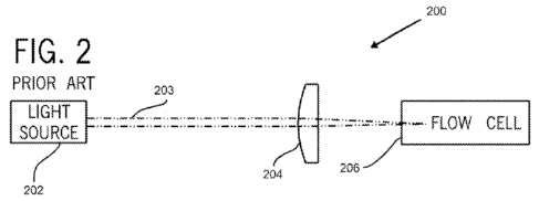
Referring now to FIG. 1, the method of obtaining data from flow cytometry
equipment typically used in the prior art involves illuminating cells 101,
102, 103
moving with the sample stream 104 by means of a stationary beam of light 105,
e.g.,
a laser beam. In FIG. 1, it can be seen that the spot (focus) of the beam of
light 105,
e.g., a laser beam, is elliptical in shape, with a relatively short vertical
axis (y) and a
relatively long horizontal axis (x); additionally, such a spot typically has
an intensity
profile (along either the short or the long axis) approximately described by a
Gaussian curve.
The method shown diagrammatically in FIG. 1 can be carried out by the
optical module depicted in FIG. 2. The optical module 200 shown in FIG. 2
comprises a source of light 202, a light beam 203, a lens or system of lenses
204, a
flowcell 206, and detectors (not shown). For the sake of simplification,
detectors,
which are required, are not shown, but are well-known to those of ordinary
skill in the
17
CA 02704699 2010-05-04
WO 2009/061710 PCT/US2008/082315
art. Other peripheral or optional components, such as mirrors, slits, prisms,
and
filters, are also not shown. The electronic module is also not shown.
In the prior art, as depicted in FIG. 1, each cell 101, 102, 103 is presented
a
varying light beam profile in the direction of flow (vertical dimension) and a
substantially uniform light beam profile over the width (horizontal dimension)
of the
sample stream 104 (because the beam of light 105 in the horizontal direction
is
made very much wider than the sample stream 104); in the prior art, the peak
of the
signal from the interaction between the light and the cell is found along the
vertical
dimension, i.e., the direction of flow.
Referring now to FIG. 3, the method of this invention involves illuminating
cells 301, 302, 303, 304, 305, 306, 307, 308, 309 moving with the sample
stream
310 by means of a beam of light 311, e.g., a laser beam, which is caused to
raster
by means of a deflection device. It can be seen that the spot (focus) of the
beam of
light, e.g., the laser beam, is elliptical in shape, with the vertical axis
(y") being
substantially equal in length to the vertical axis (y) of the beam of the
prior art and
the horizontal axis (x') being substantially shorter than the horizontal axis
(x) of the
beam of the prior art. In FIG. 3, the spot (focus) of the laser beam is caused
to
sweep across the flow stream in a direction parallel to the horizontal axis
(x').
The method shown diagrammatically in FIG. 3 can be carried out by the
optical module shown schematically in FIG. 4. In FIG. 4, the essential
components
of the optical module 400 are a source of light 402 for providing a beam of
light 403,
a deflection device 404, at least one optical element such as, for example, a
lens or
system of lenses 406 for focusing the beam of light 403, a flowcell 408, and
at least
one detector (not shown). For the sake of simplification, detectors, at least
one of
which is required, are not shown, but are well-known to those of ordinary
skill in the
art. Other peripheral or optional components, such as mirrors, slits, prisms,
and
filters, are also not shown. The electronic module is also not shown. The lens
406
serves the dual function of: (1) focusing the approximately collimated beam of
light
403 onto the flowcell 408; and (2) converting the angular sweep of the beam of
light
403 introduced by the deflection device 404 into a parallel lateral
translation of the
beam 403 across some portion of the flowcell 408. These functions are achieved
by
placing the lens 406 approximately one focal length away from the deflection
device
404 and one focal length away from the flowcell 408. Other optical
configurations for
achieving substantially the same effect of varying the transversal position of
the
18
CA 02704699 2010-05-04
WO 2009/061710 PCT/US2008/082315
beam spot at the flowcell while varying as little as possible the position of
the
propagating beam (and any scattered beam of light or any beam of emitted
fluorescent light) beyond the flowcell exist, by means of both altered
locations of
components, or by means of the insertion of additional components, or by means
of
both altered locations of components and insertions of additional components.
In the scheme of the invention described herein and depicted in FIG. 3, each
cell 301, 302, 303, 304, 305, 306, 307, 308, 309 is presented a varying
profile in both
the horizontal direction and in the vertical direction of the sample stream
310,
because the beam of light 311 is made smaller than the width of the sample
stream
310. The determination of peak intensity is then achieved in two steps. In the
first
step, peak intensity is determined "horizontally" (across) the sample stream
310, with
rapid digitization and isolation of peaks from individual raster scans in the
horizontal
direction. In the second step, peak intensity is determined "vertically" in
the sample
stream 310 by analyzing multiple raster scans and fitting the sequence of peak
values to a curve that represents the profile of the beam of light 311 in the
vertical
direction, and extracting the peak of such a fitted curve; alternatively, such
a curve
and its peak can be obtained by applying appropriate digital filtering to the
sequence
of peak values.
The deflection device 404 can be an AOD or an AOM. The essential
components of systems of the prior art include a source of light, a lens or
system of
lenses, a flowcell, and appropriate detectors. In both the prior art and in
the method
described herein, the sources of light, the lens and the systems of lenses,
the
flowcells, and the detectors, and the functions thereof in a flow cytometry
system,
are well-known to those of ordinary skill in the art. See, for example, United
States
Patent Nos. 5,017,497; 5,138,181; 5,350,695; 5,812,419; 5,939,326; 6,579,685;
6,618,143; and United States Patent Publication No. 2003/0143117 Al, where
sources of light, lenses, flowcells, and detectors are described in greater
detail. All
of these references are incorporated herein by reference. See also
http://biology.berkeley.edu/crl/flow-cytometry_basic.html, March 30, 2006,
pages 1-
7, incorporated herein by reference. Lasers, lenses, flowcells, and detectors
suitable
for use in this invention are used in commercially available instruments from
Abbott
Laboratories, Abbott Park, IL, under the trademark CELL-DYN .
Acousto-optic modulators (AOMs) and acousto-optic deflectors (AODs) are
well-known in the art of laser physics and optical technology. An AOD, also
19
CA 02704699 2010-05-04
WO 2009/061710 PCT/US2008/082315
sometimes known as a Bragg cell, uses the acousto-optic effect to dynamically
diffract, and thereby to deflect, a beam of light using sound waves (usually
at radio
frequency). An AOM can also be used to shift the frequency of the light beam.
AOMs are used in lasers for Q-switching, in telecommunications for signal
modulation, and in spectroscopy. A piezoelectric transducer is attached to a
material
such as glass or quartz. An oscillating electrical signal drives the
transducer to
vibrate, which creates sound waves in the glass or quartz. These can be
thought of
as moving periodic planes of expansion and compression that change the index
of
refraction of the optical medium. Incoming light interacts with the resulting
periodic
index modulation in a process called Bragg diffraction, and is deflected at an
angle
with respect to the incoming beam direction. The properties of the light
exiting the
AOM can be controlled in five ways: (a) deflection angle, (b) intensity, (c)
frequency,
(d) phase, and (e) polarization. AOMs are much faster than typical mechanical
devices, such as tiltable mirrors. The time it takes an acousto-optic
modulator to
alter the exiting beam is roughly limited to the transit time of the sound
wave across
the beam (typically 5 to 100 microseconds): this is sufficiently fast to
create active
modelocking in an ultrafast laser. Through careful design, transit times as
low as a
few hundred nanoseconds can be achieved. (It is noted that this represents the
maximum time required to move the beam across the entire angular deflection
range, and not the time necessary to deflect the beam from one angular
position to
one immediately adjacent to it. In other words, for specific applications,
such as in
the present invention, where the required sweeping is smooth across the scan
range, considerably faster performance can be obtained than is the case for
truly
random-access deflection at an arbitrary angle. The only requirement is that
there
must be compensation for the amount of optical distortion potentially
introduced into
the light beam by the fast sweeping action by using a weak external optical
element,
such as a cylindrical lens.) AOMs offer fast response, good deflection range,
simple
solid-state design with no moving parts, and relatively low power consumption.
Through the use of an AOM, a light beam is diffracted into several orders. By
vibrating the material with a high-quality sinusoid and orienting the AOM to
optimize
deflection into the first diffraction order, up to 90% deflection efficiency
can be
achieved.
Use of the laser rastering technique described in co-pending United States
Patent Application Serial No. 11/934,277, incorporated in full herein by
reference, in
CA 02704699 2010-05-04
WO 2009/061710 PCT/US2008/082315
conjunction with the lysis-free single-dilution method of analyzing samples,
will result
in significant improvements in measurement rates. In the system of the present
invention, a suitable deflection device is an acousto-optic deflector.
In the discussion that follows, the source of light is a laser. However, as
stated previously, other sources of light can be used, such as, for example,
lamps
(e.g., mercury, xenon). Lasers include, but are not limited to, high-power
water-
cooled lasers (e.g., argon, krypton, dye lasers), low power air-cooled gas
lasers
(e.g., HeCd (UV), argon (488 nm), red HeNe (633 nm)); and solid-state and
diode
lasers (violet, blue, green, red). The laser beam is assumed to have a varying
intensity profile, such as, for example, a Gaussian profile, in two
directions.
Referring now to FIG. 5, in the prior art the cell 502 traverses the
stationary
light beam spot 504 as the cell 502 is carried along within the sample stream.
As the
cell 502 is exposed to portions of the beam spot 504 with varying intensity,
the
resulting amount of signal intensity 506 (initially in the form of scattered,
or absorbed
light, or emitted fluorescent light; and, after detection, in the converted
form of
electronic current or voltage) varies in accordance with the profile of the
beam 504 in
the direction (vertical in this depiction) traversed by the cell 502. In the
prior art, this
signal 506 is typically further detected by electronic circuitry that
identifies the peak
value 508 of the varying interaction between the light beam spot 504 and the
cell 502
and stores it, typically in analog form, for subsequent digitization. This
method of
obtaining the value of interaction between a cell and a light beam is referred
to in the
prior art as "peak-and-hold."
Referring now to FIG. 3 for the method described herein, the beam is swept
across the sample stream. As the beam is swept across the sample stream, each
of
the signals from the detectors (after suitable conditioning by circuitry
described
below) is sampled at a high frequency by an analog-to-digital converter (ADC).
FIGS. 6A, 6B, 6C, 6D, and 6E show this process for the signal from one
representative detector channel. These signals are generated by scattered or
absorbed light or emitted fluorescent light. The digitized peak value of the
series
derived from the full interaction with a cell is stored for later use. FIGS.
6A, 6B, 6C,
6D, and 6E are schematic diagrams, along with graphs, illustrating the
progressive
interaction of a laser beam with a cell, as the laser beam, which has a
standard two-
dimensional Gaussian profile, sweeps across the cell in the sample stream. In
these
figures, the beam traverses the cell, while the position of the cell is
essentially fixed
21
CA 02704699 2010-05-04
WO 2009/061710 PCT/US2008/082315
(because the rate of flow of the cell in the sample stream is much lower than
the rate
of scanning by the beam). In each of FIGS. 6A through 6E, inclusive, the graph
positioned on the right of each diagram illustrates the value of the digitized
signal
resulting from each interaction depicted, along with the values of the
previous
interactions. FIG. 6A shows the laser beam 600 making an initial contact with
the
cell 602. FIG. 6B shows the laser beam 600 significantly overlapping the cell
602.
FIG. 6C shows the laser beam 600 centered on the cell 602, with the resulting
interaction being at or near a maximum value. FIG. 6D shows the laser beam 600
significantly, but not maximally, overlapping the cell 602. FIG. 6E shows the
laser
beam 600 making one of its final contacts with the cell 602. FIG. 6F indicates
the
intensity of the signal as a function of time, with representative values
shown from
the interactions partially illustrated in FIGS. 6A through 6E, inclusive. The
highest
digitized value from this sequence, here depicted in FIG. 6C, is isolated from
the rest
of the values and stored either in working internal registers or in dynamic
memory in
the digital signal processing (DSP) module.
Next, as the laser beam scans the sample stream in successive sweeps, the
light from the laser beam interacts with each individual cell a plurality of
times, as
shown in FIGS. 7A, 7B, and 7C. Each of these interactions results in a
digitized
peak value (for each detection channel), which is determined and stored as
previously described. Because the interactions occur at different points on
the beam
profile, the interactions, in effect, sample the beam profile at discrete
intervals -
separated by the time taken to complete a single raster cycle. The DSP module
collects the sequence of peak values from successive raster scans attributed
to a
single cell and correlates such sequence by at least one algorithm to the
profile of
the laser beam. The peak of the thus fitted curve is then further processed by
downstream algorithms, as in a conventional instrument, for cell
identification and
counting. For example, FIG. 7A shows the result of an interaction wherein the
laser
beam 700 first contacts a cell 702. FIG. 7B shows the result of the subsequent
interaction, during the immediately following raster scan, wherein the same
cell 702
as in FIG. 7A has advanced further in the sample stream and interacts
relatively
close to the central portion of the laser beam 700. FIG. 7C shows the result
of a
third subsequent interaction, during the following raster scan, wherein the
same cell
702 as in FIGS. 7A and 7B has advanced further in the sample stream and
interacts
with the shoulder of the laser beam 700. FIG. 7D shows schematically the
process
22
CA 02704699 2010-05-04
WO 2009/061710 PCT/US2008/082315
of arranging the peak values A, B, C from the interactions depicted in FIGS.
7A, 7B,
and 7C, respectively, into a sequence ordered by scan number; and the
additional
process of extracting from such an ordered sequence the inferred peak value
710,
by adapting (via at least one algorithm, at least one mathematical expression,
or at
least one electronic technique, or any combination of the foregoing) to the
sequence
a curve 712 representing the expected shape of the interaction, such shape
depending mainly on the profile of the laser beam 700 in the vertical
direction,
particularly the width of the laser beam 700. The rastering frequency, the
width of the
sample stream, and the velocity of the sample stream must be set so that each
cell
is intercepted a plurality of times as it flows past the beam of light.
A depiction of the laser rastering method described herein, but with a
plurality
of cells to illustrate how the measurement rate is increased without
increasing
coincidences, can be seen in FIGS. 8A, 8B, 8C, 8D, 8E, 8F, 8G, 8H, 81, 8J, 8K,
8L,
and 8M. FIGS. 8A through 8M, inclusive, illustrate the movement of three cells
801,
802, and 803 moving within a sample stream 804. The cell 801 is ahead of the
cell
803 by a slight distance in the sample stream 804; the cell 801 is ahead of
cell 802
by a greater distance in the sample stream 804. The cells 801, 802, and 803
are
moving upwardly. The cells 801, 802, and 803, which are merely just three of
the
cells in the sample stream 804, are illuminated by a beam of light 805, which
is
rastered, i.e., is swept from side to side, by a deflection device, such as,
for example,
an AOD. The sweeping movement of the beam describes a band 806, in sample
stream 804, where cells are illuminated by the light beam at some point in the
course
of each raster scan. The series of horizontal lines 0 through 12, inclusive,
below the
sample stream 804, illustrates the sequence of varying signals (taken, for
example,
directly at the output of a representative detector channel) generated by each
cell, or
a plurality of cells, at a well-defined point in each scan. For example,
during scan 0
(FIG. 8A), none of the cells 801, 802, 803 have interacted with the beam 805
in the
region 806. Line 0 indicates the lack of a signal peak. During scan 1 (FIG.
8B), the
cell 801 interacts with a low-intensity portion of the beam 805, but the cells
802 and
803 have not yet interacted with the beam 805. Line 1 indicates a low signal
peak
for the interaction of the beam 805 with the cell 801. During scan 2 (FIG.
8C), the
cell 801 interacts with a portion of the beam 805 that is intermediate to the
low-
intensity portion of the beam 805 and to the high-intensity portion of the
beam 805,
but the cells 802 and 803 have not yet interacted with the beam 805. Line 2
23
CA 02704699 2010-05-04
WO 2009/061710 PCT/US2008/082315
indicates a higher signal peak for the interaction of the cell 801 with the
beam 805
than was observed during scan 1 (Line 1). During scan 3 (FIG. 8D), the cell
801
interacts with a high-intensity portion of the beam 805, the cell 803
interacts with a
low-intensity portion of the beam 805, but the cell 802 has not yet interacted
with the
beam 805. Line 3 indicates the signal peaks for the interaction of the beam
805 with
the cell 801 (highest signal peak, at left, for the cell 801) and with the
cell 803 (low
signal peak, at right, for the cell 803). During scan 4 (FIG. 8E), the cell
801 interacts
with a portion of the beam 805 intermediate to the high-intensity portion of
the beam
805 and to the low-intensity portion of the beam 805, the cell 803 interacts
with a
portion of the beam 805 that is intermediate to the low-intensity portion of
the beam
805 and to the high-intensity portion of the beam 805, but the cell 802 has
not yet
interacted with the beam 805. Line 4 indicates the signal peaks for the
interaction of
the beam 805 with the cell 801 (intermediate signal peak for the cell 801) and
with
the cell 803 (intermediate signal peak for the cell 803). Table 1 summarizes
the
results of the aforementioned interactions of the cells 801, 802, and 803 and
the
remaining interactions of the cells 801, 802, and 803 with the beam 805 across
the
region 806 up to the point where the cell 802 departs the region 806 of
illumination
by the beam 805. It should be noted that FIGS. 8A, 8B, 8C, 8D, 8E, 8F, 8G, 8H,
81,
8J, 8K, 8L, and 8M depict schematic, not actual, interactions of the cells
with the
beam. In Table 1, there are four types of interactions depicted: (a) no
interaction,
when no part of the beam 805 intersects a cell; (b) low signal peak, when a
low-
intensity portion of the beam 805 intersects a cell; (c) high signal peak,
when a high-
intensity portion of the beam 805 intersects a cell; and (d) intermediate
signal peak,
when the cell intersects a portion of the beam 805 that is intermediate to the
low-
intensity portion of the beam 805 and to the high-intensity portion of the
beam 805.
These four types of interactions are also intended to be schematic and do not
imply
that only four distinct levels of interaction can result from the apparatus
and method
disclosed herein; indeed, the interactions can take any of a very large set of
values,
depending on, for example, the relative sizes of cells, the intensity of the
laser beam,
and the presence and degree of noise (whether optical, biological, or
electrical) in
the system.
24
CA 02704699 2010-05-04
WO 2009/061710 PCT/US2008/082315
TABLE 1
Scan no. (FIG. no.) Character of signal Character of signal Character of
signal
peak based on peak based on peak based on
intersection of the cell intersection of the cell intersection of the cell
801 with the beam 802 with the beam 803 with the beam
805 in region 806 805 in region 806 805 in region 806
0(8A) none none none
1 (8B) low none none
2 (8C) intermediate none none
3 (8D) high none low
4 (8E) intermediate none intermediate
(8F) low none high
6 (8G) none none intermediate
7 (8H) none low low
8 (81) none intermediate none
9 (8J) none high none
(8K) none intermediate none
11 (8L) none low none
12(8M) none none none
The sequence shown in FIGS. 8A through 8M, inclusive, constitutes a
discrete sampling of the profile of the beam of the source of light 805.
Correlation
(by fit, filtering, other algorithm, or dedicated electronic circuit) of the
sampled
interactions with a curve representing the profile of the light beam in the
vertical
direction occurs in real time on, and in the immediate vicinity of, all the
points along
the digitized raster scans, where there is a non-zero peak. Such points are
diagrammatically indicated by the dashed lines in FIGS. 8A through 8M,
inclusive.
Accordingly, each separate sequence of detected peaks belonging to a single
cell
can be fit to a representation of that profile. By using the technique of
rastering
described herein, the cells 801, 802, and 803 can be distinguished from one
another,
even though two or more of them may pass through the illumination region 806
simultaneously (or in partial simultaneity, as depicted in FIGS. 8A through 8M
by
cells 801 and 803, and separately by cells 803 and 802), because the cells
interact
with the beam 805 at different points of each raster scan. Accordingly, the
technique
of rastering enables a flow cytometer to analyze a greater number of cells per
unit
CA 02704699 2010-05-04
WO 2009/061710 PCT/US2008/082315
time, while the number of coincidences can be maintained at an acceptably low
level.
The processing of the signals, from each detector, following the interactions
illustrated in FIGS. 8A through 8M, is depicted schematically in FIG. 9. The
block
diagram 900 shows a collection of detectors 902, 904, ... (two detectors are
shown
as representative of an optionally larger set). Each detector is connected to
a
separate preamplifier circuit 912, 914, ... (again, two preamplifier circuits
are shown
as representative of an optionally larger set commensurate with the number of
detectors used). The preamplifier circuits for the various detectors may
physically
reside on the same electronic submodule, or they may be partitioned according
to
electrical requirements (such as, for example, noise isolation, voltage supply
requirements, physical proximity to the detector, etc.) pertaining to each
detector, or
some portion of them may be combined and some portion kept separate. The
signals from each detector so amplified by each preamplifier circuit then
progress
through an analog signal- conditioning submodule 920. The functions of this
submodule include reduction or elimination of dc or quasi-dc offsets from each
of the
signals (a process also known as baseline restoration), partial or complete
compensation of nonuniformities in the intensity of the light delivered to the
flowcell
as a function of position along the raster scan (a process also known as AOD
intensity compensation), and optionally filtering to reduce or remove, for
example,
high-frequency noise from each of the signals. The signals in each channel so
conditioned then proceed to the analog-to-digital converter (ADC) submodule
930,
where each signal channel has a dedicated ADC channel clocked at high
frequency
(at the level of 100 million samples per second, MS/s, for each channel) and
sufficient resolution (about 14 bits). The function of the ADC submodule 930
is to
convert the analog signals in each channel of detection into digitized values
and
discrete, but closely spaced, time intervals, as shown, for example, in FIG.
6F. The
signals so digitized then progress to the digital signal processing (DSP)
submodule
940. This submodule 940 can comprise either a single powerful field-
programmable
gate array (FPGA) 942, or a DSP chip 944; or, optionally, a plurality of FPGAs
or
DSP chips, or both a FPGA and a DSP chip, or a plurality of FPGAs and a
plurality
of DSP chips, depending on the speed and computational requirements of the
specific application of the analyzer in which they are incorporated.
Additionally,
submodule 940 preferably comprises: (a) random access memory (RAM) units 946
26
CA 02704699 2010-05-04
WO 2009/061710 PCT/US2008/082315
for optional intermediate storage of data for computation, for staging data
before
transmission over a data bus or other means of conveyance to the next stages
of
processing, or for both intermediate and staging data storage; and (b) a
digital-to-
analog converter (DAC) unit 948 that takes inputs from the FPGA(s) 942, the
DSP(s)
944, or both the FPGA(s) 942 and the DSP(s) 944 and converts them into analog
signals. These analog signals are used to dynamically, or programmatically,
alter
the operating parameters (e.g., supply voltage) of portions or a totality of
the
detectors 902, 904, ...; the operating parameters (e.g., gain settings) of the
preamplifier submodules 912, 914, ...; the operating parameters (e.g., amount
of dc
or quasi-dc offset) of the analog submodule 920; or a combination of operating
parameters of detectors, preamplifiers, and analog submodule. The functions of
the
DSP submodule 940 are to: (a) select the highest digitization value from a
cell
interaction during a single raster scan (or a plurality of such values, if
more than a
single cell is present during a single raster scan as shown, for example, in
FIG. 8E);
(b) to optionally apply a known factor to the values thus identified, based on
their
position along the raster scan, in order to effect any necessary residual AOD
intensity compensation not already executed in the analog submodule 920; (c)
to
correlate such highest values across successive raster scans in order to
reconstruct
the peak value of the interaction between each cell and the laser beam spot
(as
illustrated in, for example, FIGS. 7D and 8M); (d) to apply programmatically
predetermined numerical upper, lower, or upper and lower, thresholds, specific
to
each channel of detection, to the peak values so reconstructed in order to
select out
of the population of detected events those that, within a particular assay,
are most
likely to represent the population of interest, and to reject or differently
classify the
remainder; and (e) to coordinate the information thus constructed and
filtered,
coming from each individual channel of detection, into a digital entity
(typically
referred to as one element of a "listmode" file) that contains time-stamp
information
as well as the reconstructed values from each of the channels of detection
involved
in the measurement pertaining to that same individual cellular transit event.
The
collection of listmode events is then collated into one or a plurality of
listmode
batches, which can be temporarily stored, e.g., in RAM units 946. The batches
of
data can then be periodically transferred (from the RAM units 946, or directly
from
the FPGA 942, or directly from the DSP chip 940, if present; and through
appropriate
data channels, such as, for example, a Peripheral Component Interconnect (PCI)
27
CA 02704699 2010-05-04
WO 2009/061710 PCT/US2008/082315
bus), at times determined by means of a program, to the operating system of
the
analyzer (AOS) 950 for further processing by algorithms, such as, for example,
algorithms for identifying cells, counting cells, and flagging cells. The DSP
submodule 940 can optionally incorporate the ADC submodule 930, and can also
optionally incorporate the analog submodule 920.
The apparatus and method described herein provides an instrument that
maintains satisfactory performance with respect to precision, coincidences,
and
signal-to-noise ratio. The method of the present invention allows selection of
rastering speeds and flow stream parameters to conform to the desired
digitization
frequency and to allow multiple scans over a single cell. The present
invention can
be implemented with commercially available components (e.g., AOD, ADC, FPGA).
The apparatus and method described herein can provide a substantial
improvement
in the measurement rate (cells analyzed per second). This improvement results
in:
(a) a reduction in the time required to perform a standard CBC, thereby
yielding a
higher throughput (CBC/hr); (b) an increase in the total number of cells
analyzed per
sample run, thereby yielding higher statistical precision in the determination
of, in
particular, the existence, the concentration, or the existence and the
concentration of
relatively rare cellular events; or (c) a combination of both a higher
throughput and
an increase in the number of total cells analyzed. In addition, the apparatus
and
method described herein provides a significant reduction in the complexity of
the
analyzer, in the number of separate processing steps required for a standard
CBC,
in the number and amount of reagents used to obtain a CBC, in the cost of its
manufacture, in the risk of failure during operation, and in the cost of
maintenance
and service. Furthermore, the apparatus and method described herein eliminates
the need to lyse RBCs during the WBC assay, thereby eliminating the
interference
with the WBC count or differential assay from lyse-resistant RBCs (including,
e.g.,
sickle cells, target cells, and RBCs from neonates).
The conditional constraints of the present invention are summarized by the
following
mathematical relationships:
28
CA 02704699 2010-05-04
WO 2009/061710 PCT/US2008/082315
#I (peak signal strength) : Pas. r > Paser
Wox Woy WoxWoy
r
#2 (integrated signal strength) : Paser > Piaser
Woyxstream raster Woxvstream
#3 (coincidences) : p' Wox Woy Zst eam C p xstream Woy Zstream
r /r
#4 (multiple digitizations over cell) : W ox digitization {'~ >_ 10
xstream/ raster
#5 (digitization constraint) : fdigitization <_ 125 MHz
f,
#6 (multiple raster scans over cell) : Wo raster > 3
Vstream
#7 (rastering constraint) : fraster <_ 1 MHz
#8 (measurement rate requirement) : p'xs~eamzst eamvst eam P xst eamZst eamvst
eam
where
Piaser represents the laser beam power,
Wox and Woy represent the dimensions of a focused spot (i.e., at or near the
waist) of a laser beam (horizontal and vertical, respectively),
Xstream and Zstream represent the dimensions of the sample stream (width and
depth, respectively),
Vstream represents the velocity of the sample stream,
(digitization represents the digitization frequency,
,/raster represents the frequency of repetition of the raster scans,
and where the parameters represented by primed symbols indicate the parameter
values in the apparatus and method described herein, and the parameters
represented by unprimed symbols indicate the parameter values in the prior
art. As
used herein, the expression "conditional constraint" means a value expressed
as a
mathematical relationship for establishing target operating conditions for a
flow
cytometry apparatus and method. It is to be understood that such constraints
are
only broadly indicative of the ultimate operating conditions selected for
implementation, such as, for example, constraints attributable to
technological
limitations, such as the speed of electronic components, which can be relaxed
by the
introduction of improved devices. Also, other constraints may represent the
absolute
29
CA 02704699 2010-05-04
WO 2009/061710 PCT/US2008/082315
minimum requirement for a particular operating parameter, wherein good
engineering design considerations would suggest adoption of a value of such a
parameter with a margin of tolerance for manufacturing, operating, and
specimen
variabilities.
Turning to the signal strength parameters, condition #1 (peak signal strength)
is defined by the following relationship:
laser > Plaser condition #I
WoxWoy WoxWoy
This relationship states the requirement for the (average) photon flux, or
intensity of
the beam, at the cell: the smaller the beam spot, the higher the intensity for
a given
power. Whereas the signal processing system primarily records the peak height
of
the resulting signal as the parameter of interest (which is widespread
practice in the
prior art for the handling of scattering signals), in order to ensure that the
peak signal
strengths are comparable to those in the prior art, condition #1 states that,
for a
smaller beam spot, a proportionately lower laser power will suffice.
Condition #1 is to be compared to condition #2 (integrated signal strength),
where another relationship applies:
laser > laser condition #2
Woy'xstreamfraster Woxvstream
This relationship reflects the fact that, where the time-integrated signal is
the
recorded parameter of interest (as is the case in some instances of the prior
art for
scattering signals, and more generally the case in the prior art for
fluorescence
signals), the relevant quantities include not only the intensity of the light
beam at the
cell, but also the length of time the beam interacts with the cell. In a laser
rastering
system, the generally smaller beam spot yields a higher intensity, as compared
with
the prior art (automatically satisfying condition #1 if the laser power is
unchanged),
but the relatively shorter time of interaction could yield a lower integrated
signal,
even though the average beam intensity is higher. Thus, if integrated signals
are
required, a somewhat higher laser power may be necessary to maintain parity
with
the corresponding signals from a system of the prior art that does not employ
rastering.
CA 02704699 2010-05-04
WO 2009/061710 PCT/US2008/082315
Turning now to the coincidences parameter, FIG. 10 shows diagrammatically
an approximate illuminated volume of the prior art, and FIG. 11 shows
diagrammatically an approximate illuminated volume encountered in the present
invention. The following two relationships provide the parameters utilized to
determine the number of cells in the volume illuminated at any instant of
time. The
term "current" refers to the prior art. The term "new" refers to the present
invention.
NCeõs = pxstreamWOYZS eam current number of cells in illuminated volume
NCeõs = p'W XWoyZstream new number of cells in illuminated volume
In the prior art, the cell concentration p depends on the assay. It is highest
for a
RBC and platelet assay (see, for example, the CELL-DYN Sapphire , where the
dilution ratio for such assay is 1:290) and lowest for a WBC assay (where the
dilution
ratio is 1:35, but where the relatively very numerous RBCs and platelets have
been
excluded using a combination of biochemical and electronic rejection means).
In the
apparatus and method described herein, there is a single dilution, with
concentrations of the different cell populations proportionate to their
undiluted
concentrations in human whole blood. For the purpose of estimating coincidence
levels, however, the population that matters the most is the most numerous; it
is the
concentration of this population to which the quantity p' refers. With these
conventions, condition #3 (coincidences) can be defined by the following
relationship:
p 'W ox Woy zstream p Xst eam Woy Zstream condition #3
Turning now to the digitizations parameter, FIG. 12A shows diagrammatically
the interaction of a laser beam spot 1200 with a cell 1202. FIG. 12B shows a
hypothetical plot of signal intensity as a function of time. FIG. 12C shows a
hypothetical plot of digitizations developed by an analog-to-digital
converter. Based
on the following relationships, i.e.:
31
CA 02704699 2010-05-04
WO 2009/061710 PCT/US2008/082315
_ Wox
tinteraction ,
Vraster
= W x interaction time
'stream raster
taigitizat on = { , 1 digitization time
digitization
condition #4 (multiple digitizations over cell) can be defined by the
following
relationship:
Wox/ digitization > 10 condition #4
r r
'stream raster
where the number 10 is selected to nominally indicate the approximate number
of
digitizations required to capture with sufficient accuracy the varying profile
of the
signal from interaction between the laser beam and a cell in the course of any
single
raster scan.
For condition #5 (digitization constraint), the mechanism of ADCs is such that
a trade-off relationship exists between the digitization frequency and the
depth of
resolution. The fastest commercially available analog-to-digital
converters can digitize with 14-bit resolution at 125 MHz or with 16-bit
resolution at
100 MHz. For the purpose of the apparatus and method described herein, a 14-
bit
resolution is adequate, while the highest possible frequency of digitization
is desired.
Therefore,
{d'digitization <_ 125 MHz condition #5
where the condition is meant to indicate the constraint imposed by the
performance
of currently available technology, and not the maximum digitization frequency
desired in principle for the purpose of this invention.
Turning now to the multiple raster scans parameter, hypothetical scans 1, 2,
3, 4, and 5 of FIG. 13 diagrammatically show the position of a cell 1300
during each
of a plurality of scans of the laser beam 1302. Here y scan represents the
distance
32
CA 02704699 2010-05-04
WO 2009/061710 PCT/US2008/082315
advanced by a cell during one scan, and w"oy represents the beam spot size
along
the vertical axis of the elliptical beam. Based on the following
relationships, i.e.:
traster = I raster period
f raster
_ ,
Yscan - Vstreamtraster
f
= Vst eam distance advanced in one scan
f raster
woy vertical beam spot size
condition #6 (multiple raster scans over cell) can be defined by the following
relationship:
woy/ raster
>_ 3 condition #6
Vstream
where the number 3 is selected to indicate the minimum number of scans
required to
allow, in principle, a reconstruction of the Gaussian curve representing the
interaction between the laser beam and a cell in the course of multiple raster
scans.
For condition #7 (rastering constraint), the mechanism of AODs is such that a
trade-off relationship can exist between the range of deflection angles and
the
frequency of rastering. For the purpose of the current invention, the range of
deflection angles can be relatively small, while the highest possible
frequency of
rastering is desired. Commercially available AODs optimized for this purpose
can
effect sweeps over approximately 1 to 2 mrad at a maximum repetition frequency
of
approximately 1 MHz. Therefore,
/ raster <_ 1 MHz condition #7
where the condition is meant to indicate the constraint imposed by the
performance
of currently available technology, and not the maximum rastering frequency
desired
in principle for the purpose of this invention.
Turning now to the measurement rate parameter, FIG. 14 shows
diagrammatically a volume of sample of the prior art measured in a given unit
of time
33
CA 02704699 2010-05-04
WO 2009/061710 PCT/US2008/082315
and FIG. 15 shows diagrammatically a volume of sample measured in the same
unit
of time, according to the apparatus and method described herein, which volume
can
be substantially larger than that in the prior art. The reason for the
difference is that
in the prior art, the volume measured per unit time depends mainly on the
illuminated
volume and on the stream velocity, whereas in the apparatus and method
described
herein, the volume measured per unit time is augmented by the rastering
process to
include multiples of the illuminated volume. It is important to differentiate
between
the measurement volumes indicated in FIGS. 14 and 15 and the volume
illuminated
by the laser beam at any one instant of time, which is depicted in FIGS. 10
and 11
for the prior art and for the apparatus and method described herein,
respectively,
where such illuminated volume is intended to be substantially equivalent in
the
apparatus and method described herein and in the prior art, for an unchanged
level
of dilution. The following two relationships provide parameters to determine
the
measurement rate (defined as the number of cells detected per unit time),
where the
term "current" refers to the prior art and the term "new" refers to the
present
invention:
n = p xstreamzstream vstream current measurement rate (cells/sec)
n' p'xstreamzstreamV' stream new measurement rate (cells/sec)
Condition #8 (measurement rate requirement) is defined by the following
relationship:
Pxstreamzstreamvstream >_ Pxstreamzstreamvstream condition #8
The foregoing relationships allow one to select choices for each parameter
and verify that each condition is satisfied, and by what margin. The following
set of
approximate choices represents an embodiment suitable for use in this
invention:
34
CA 02704699 2010-05-04
WO 2009/061710 PCT/US2008/082315
Pas,, = 40 mW
wox = 10 um
woy = 20 pm
'xstream = 100
= pm
Zst eam
vstream 4 m/s
{ = 1 MHz
/ raster
digitization = 100 MHz
where the choice of laser power is made by taking into consideration both
condition
#1 and condition #2. Of the two conditions, condition #2 is the more
restrictive
condition. The foregoing values are contrasted, for example, with the
approximate
values currently employed in the CELL-DYN Sapphire hematology analyzer:
Paser = 10 mW
wox = 65 pm
woy = 20 wpm
Xstream =5 ih1
Zstream = 80 ,.cm
Vstream = 8 m/s
Through appropriate choices of parameters, all of the conditions previously
described can be satisfied, and some can be satisfied by a significant margin.
Most
importantly, the condition #8 yields the dramatic result of a five-fold
improvement in
measurement rate with respect to what is currently achieved on the CELL-DYN
Sapphire instrument. It is understood that this level of improvement in
measurement rate is indicative of a value that can be substantially increased,
within
the scope of the present invention, by judicious engineering choices or by
improvement of performance of utilized components. It is also understood that
the
foregoing choices for parameter values for the present invention are tolerant
of
significant variation without an attendant significant reduction in the value
of the
invention. For example, the rastering frequency can be reduced by some amount
or
the sample stream dimensions can be altered in order to satisfy engineering
design
CA 02704699 2010-05-04
WO 2009/061710 PCT/US2008/082315
requirements, while still providing the present invention with a substantial
advantage
in terms of measurement rate, relative to the prior art.
The overall sequence of main functional steps involved in the operation of a
hematology analyzer of the prior art is depicted schematically in FIG. 16. A
sample
is loaded into the analyzer through a mechanical interface (1602). This
interface
typically takes the form of a sample loader system that can handle sets of
racks of
pluralities of sample tubes placed in a loading area attached to the analyzer,
or,
optionally, the form of an automation system that can handle either individual
sample
tubes or an individual rack containing a plurality of sample tubes, wherein
either the
individual sample tubes or the individual racks of sample tubes are conveyed
on a
track assembly. Once the sample tube advances to the requisite position, the
sample tube is transferred to a mixing assembly that inverts the sample tube
multiple
times to ensure homogeneity of the sample (1604). Each tube containing a
sample
is then moved to a position to allow reading of an identifying barcode label
or radio
frequency identification tag (not shown), and the closure of the sample tube,
typically
a rubber stopper, is pierced by a probe assembly. The probe descends into the
sample volume and aspirates a quantity of sample (1606). This aspirated volume
is
then partitioned into several aliquots by one of various means, such as, for
example,
passing through a shear valve with fixed volumes for the different aliquots,
or
dynamically pipetting the various aliquots directly into their next stages of
processing
(1608). The different aliquots then proceed through similar parallel paths
corresponding to the respective assays to which they are allocated, such as,
for
example, the RBC and platetet assay (1610); the WBC, WBC differential, and an
assay for optional flagging, identification, and quantification of nucleated
RBCs
(1640); and, optionally, the reticulocyte assay (1670). Other assays not
shown, but
substantially similar to those shown, include an assay for quantification of
parameters related to hemoglobin, generally carried out on a separate
colorimetric
transducer requiring a strong lysing agent, and a separate aliquot of the
sample; and
an assay for counting and sizing certain subpopulations of blood cells, which
is
generally carried out on one or more separate impedance-based transducers. For
each of these assays, the respective aliquot is transferred into an
appropriate
container (1614, 1644, and 1674). Separately, the respective reagent solution
appropriate for the particular assay is metered precisely, typically by means
of a
motor-actuated syringe, a diaphragm pump, a peristaltic pump, or other
suitable
36
CA 02704699 2010-05-04
WO 2009/061710 PCT/US2008/082315
fluidic management component or subassembly (1612, 1642, and 1672). The
precise amount of reagent solution is then delivered to the same container
that
receives the aliquot of the sample (1616, 1646, and 1676), or is otherwise
brought
into contact with the aliquot of the sample for the purpose of carrying out a
reaction
therewith. The mixture of aliquot of the sample and the reagent solution, in
each
separate assay, is homogenized, either by the process of introducing the
sample and
the reagent solution into the container, or by active mixing, such as, for
example, by
vortex mixing, through bubbles, agitation, turbulence, or other means (1618,
1648,
and 1678). Depending on the assay, the homogenized mixture is then either
transferred essentially immediately to a staging fluidic section (1622 and
1682), or is
first incubated for a certain time, typically at a well-defined temperature,
in the mixing
container (1650), followed by transfer to a staging fluidic section (1652).
This
procedure is followed, for example, for WBC assays in the prior art, where
RBCs are
essentially removed by lysis during this incubation step. The various mixtures
of the
sample and the reagent solution, thus prepared, are then ready to enter the
flowcell
for measurement. In the case of hemoglobin measurements, the reacted aliquot
of
the sample can be measured colorimetrically in the same container in which the
sample was mixed with and reacted with the lysing agent; in the case of
impedance
measurements, the aliquot of the reacted sample is directed to the impedance
transducer rather than to the optical flowcell. A flow cytometer typically has
a single
flowcell, which then accepts the various prepared samples in some sequence and
where the flow cytometry measurements take place serially (for example, 1624,
1654, and 1684). The samples are then processed for disposal, and the flowcell
rinsed between adjacent measurements (1626, 1656, and 1686). As the samples
are passed through the flowcell, the resulting signals undergo processing and
are
passed to the operating system of the analyzer for analysis by the cell
counting,
identification, and flagging algorithms (1628, 1658, and 1688).
The analogue of FIG. 16 for the apparatus and method described herein is
depicted schematically in FIG. 17. In the description of the embodiment that
follows,
no separate hemoglobin transducer is present; for an embodiment including such
a
transducer in addition to the rastering optical flowcell, the incorporation of
such a
transducer adheres to schemes disclosed in the prior art and need not be shown
here. The initial stages of the sample preparation are similar to those of the
prior art,
with the analogous steps of sample loading (1702), sample homogenization
(1704),
37
CA 02704699 2010-05-04
WO 2009/061710 PCT/US2008/082315
and sample aspiration (1706). The step of providing aliquots of the sample is
eliminated, because a single volume of the sample is used for processing. The
three
or more separate assays of the prior art are combined into a single assay
(1710),
which yields those parameters that in the prior art require an assay for RBC
and
platelet parameters, an assay for WBC, WBC differential, and nucleated RBC
parameters, an assay for quantification of reticulocyte parameters, and an
assay for
quantification of parameters related to hemoglobin. The volume of sample is
delivered to a single container (1714), and the reagent solution is metered
(1712)
and delivered to the same container (1716). The resulting mixture is
homogenized
(1718); however, no incubation is necessary because of the absence of a lysing
process. The mixture of the sample and the reagent solution is then staged
(1722)
and immediately passed through the flowcell, where the flow cytometer
measurements take place (1724). There are no separate sample mixtures to be
processed sequentially; therefore, the sample is directed to waste and the
flowcell
rinsed (1726), thereby allowing another sample to follow immediately. The
signals
from the flowcell measurements are processed and analyzed by the algorithms
(1728).
FIG. 18 is a portion of a collection of actual data from the method and the
apparatus described herein. The data illustrate several key principles of
lysis-free
single-dilution method involving laser rastering: (a) the fast interaction
between the
laser beam and the cells, (b) the multiple periodic interactions of the beam
with the
same cell over several raster scans, (c) the rise-and-fall character of the
multiple
interactions, and (d) the ability of laser rastering to distinguish closely
positioned
cells in the sample stream (coincidences), which enables the high measurement
rate
required for single-dilution methods. The graph shows three plots: (1) the
solid line
represents actual data obtained from a rastering apparatus described herein
acting
on a diluted sample of human whole blood that was not subjected to a lysing
agent,
the apparatus operating at a raster scan frequency of 1 MHz and at a
digitization
frequency of 104 MS/s; (2) the open circles are a guide for the eye, and they
represent the approximate Gaussian envelope of one series of peaks in the
data;
and (3) the closed triangles are another guide for the eye, and they represent
the
approximate Gaussian envelope of a second series of peaks in the data. Each
series of peaks in the actual data is the result of the interaction of the
rastering laser
beam with one cell in the flow stream; the two series of peaks are interlaced,
38
CA 02704699 2010-05-04
WO 2009/061710 PCT/US2008/082315
indicating an event, resolved by the analyzer described herein, which would
have
been unresolved (i.e., a coincidence) in an analyzer of the prior art. The
captured
data sequence is a demonstration of rastering operation that illustrates the
schematic scenario of cells 801 and 803 depicted in FIGS. 8A through 8M. The
two
Gaussian envelopes show that the two peak series have similar widths, as would
be
expected from interaction sequences of like cells. The two cells in this case
were
RBCs.
The apparatus and method described herein can be used with any product
line that employs a laser, or other suitable light source, for carrying out
flow
cytometry or flow-cytometer-based hematology analysis. Instruments that are
suitable for use with this invention include, but are not limited to, the CELL-
DYN
Sapphire (commercially available from Abbott Laboratories) and the CELL-DYN
Ruby (commercially available from Abbott Laboratories).
One benefit of the apparatus and method described herein is a dramatic
increase in the measurement rate (cells analyzed per second), such as, for
example,
by an approximate factor of five. This increase allows (a) a reduction in the
time for
acquisition of data (time for counting cells) by the same factor, thereby
increasing the
throughput; or (b) an increase in the total counts (total number of cells
counted) by
the same factor, thereby increasing precision. An increase in precision is
particularly
important in cytopenic patients. A combination of increases in both precision
and
throughput is also feasible.
The specific effect that the combination of laser rastering and the lysis-free
single-dilution method described herein would have on actual throughput
(CBC/hr)
can be estimated by making the following assumptions: (1) the RBC lysis
incubation
step of a conventional method is removed; (2) the multiple assays of a
conventional
method are combined into a single assay; (3) the measurement rate of a
conventional analyzer is increased fivefold due to the adoption of laser
rastering; (4)
the total count time of the combined assay is based on this increased
measurement
rate, on the highest cell concentration given the allowable coincidence rates
(i.e.,
that concentration given by the dilution ratio of a conventional RBC/platetet
assay),
and on matching the desired WBC precision levels to those achieved in a WBC
assay of the conventional method.
A method based on these assumptions would result in a reduction of the
measurement time for a CBC to about 15 seconds. Allowing for some margin for
39
CA 02704699 2010-05-04
WO 2009/061710 PCT/US2008/082315
rinsing the flowcell to reduce carryover, a typical "ready-to-ready"
processing cycle
time can be estimated to be approximately 16 seconds, corresponding to an
estimated average throughput of 225 CBC/hr. This is contrasted with the
current
performance of the CELL-DYN Sapphire (105 CBC/hr), which combines the
relatively high throughput of the prior art with high first-pass
reportability; and with
the best in-class throughput of 150 CBC/hr, albeit at a relatively lower rate
of first-
pass reportability. This level of effective throughput improvement, coupled
with best-
in-class first-pass reportability, would be extremely significant from a
commercial
perspective.
An attendant benefit of the apparatus and method described herein in a
hematology analyzer or flow cytometer is the ability to independently
determine
multiple parameters closely correlated with the size of the particle(s) being
subjected
to measurement. Determining the size of cells in the sample is one of the
principal
functions of a hematology analyzer. In the prior art of instrumentation based
on flow
cytometers, determination of cell size is typically achieved by processing the
signal
from one or more of the scattering detectors, particularly the forward-
scattering
detectors, or by one or more additional dedicated transducers operating on the
principle of cell sizing based on impedance measurements. This scattering
capability of the prior art is available, unchanged, in the apparatus and
method
described herein. Another approach taken in the prior art has been to measure
the
so-called "time of flight," namely the time it takes a particle to traverse
the stationary
laser light beam spot. Referring to FIG. 5, i.e., the prior art, time of
flight would be
approximately represented by the width of the interaction signal curve 506.
(This is
actually a correlation of the size of the particle and the width of the laser
beam spot;
if the laser beam spot size is known, the particle size can be determined.) In
the
apparatus and method described herein, there are several opportunities for
obtaining
a time-of-flight measurement of the size of the cell under scrutiny. First,
each raster
scan that interacts with a cell can optionally return a value for the width of
such
interaction. Referring to FIGS. 7A, 7B, and 7C, the width of each of the
interaction
curves represents an independent measurement of the size of the cell 702. The
availability of a multiplicity of such determinations provides a statistical
robustness of
precision to the collection of size values that is unmatched by a single
determination,
such as is used in the prior art. Second, referring to FIG. 7D, the
correlation across
raster scans that yields the peak value 710 of the interaction curve 712 can
likewise
CA 02704699 2010-05-04
WO 2009/061710 PCT/US2008/082315
yield the width of such interaction. This determination represents an
additional
measurement of the size of the cell, which can be combined and correlated with
the
determinations from each raster scan to result in a robust collection of
measurements related to size not only independent of, but also augmenting,
those
derived from the scattering information itself.
A significant benefit derived from the apparatus and method described herein
is the reduction in components, subsystems, reagents, operating firmware,
operating
software, and overall design complexity that is enabled by the lysis-free
single-
dilution approach being combined with the rastering method. For example, each
of
the two or more delivery subsystems that is eliminated by adoption of the
present
invention would typically include the following components: (a) a precision
metering
syringe; (b) a syringe assembly; (c) a syringe stepper motor; (d) a stepper
motor
driver board; (e) several lengths of noncompliant tubing; (f) several pinch
valves; (g)
the corresponding pilot valves that operate the pinch valves, or alternatively
the
solenoids operating the pinch valves; (h) the electronic board components
driving the
pilot valves or the solenoids; (i) a container used to mix one aliquot of
sample with
the metered quantity of reagent; (j) a motor used to mix the sample aliquot
with the
reagent solution; (k) the mixer motor driver board; (I) the firmware necessary
to
control operation of the stepper motor, the mixer motor, and the several pilot
valves
or solenoids; (m) the current capacity necessary to power the stepper motor,
the
mixer motor, and the pilot valves or solenoids; (n) the fans necessary to
remove the
heat from the flow panel due to operation of the pilot valves or solenoids.
Taking as
example the CELL-DYN Sapphire , where three reagent delivery subsystems
supporting flow cytometry measurements are currently in use (that for the
RBC/platetet assay; that for the WBC, WBC differential, and nucleated RBC
assay;
and that for the optional reticulocyte assay), adoption of the apparatus and
method
described herein would reduce these to a single reagent delivery subsystem.
Subsystems supporting impedance measurements (for cell volume determination)
or
colorimetric measurements (for hemoglobin determination) need not be affected.
However, these subsystems, too, could optionally be eliminated altogether for
additional benefits in simplicity, reliability, and cost, because the
apparatus and
method used for lysis-free single-dilution approach could provide all of the
reportable
parameters (including mean cell volume and average hemoglobin content) that
are
required of a commercial hematology analyzer.
41
CA 02704699 2010-05-04
WO 2009/061710 PCT/US2008/082315
The apparatus and method described herein can be utilized in various
environments through the use of a modular approach. A very fast version
(leveraging the aspect of the apparatus and method related to the reduction in
the
time required for a CBC) can be used for high-volume applications in reference
laboratories and hospital core laboratories, optimized for effective
throughput, and
possibly without monoclonal antibody features. A very precise version
(leveraging
the aspect of the apparatus and method related to the increase in total number
of
counted cells in a given unit of time) can be aimed at tertiary-care centers,
optimized
for performance on rare events and cytopenic samples, and including monoclonal
antibody features.
The reagents used in the analyzer are reduced from the set in the prior art
(which includes a lysing agent for use in the WBC assay, an optional nucleic
acid
dye added to the lysing agent for use in the concurrent nucleated RBC assay, a
diluent solution containing optional sphering reagent for the RBC/platetet
assay, and
a reagent solution used for the reticulocyte assay, which reagent solution
includes a
nucleic acid dye, and, optionally, a strong lysing agent used for hemoglobin
quantification) to a single reagent solution, which comprises a diluent,
typically a
saline diluent. The single reagent solution preferably comprises a sphering
reagent.
The single reagent solution optionally comprises one or two nucleic acid dyes
for
reticulocyte and NRBC analysis. At least one of the nucleic acid dyes should
be
capable of staining RNA, and at least one of the nucleic acid dyes should be
capable
of staining DNA. Alternatively, the at least one nucleic acid can be capable
of
staining both RNA and DNA. Another optional ingredient of the reagent solution
for
use in the method described herein is a selective permeabilizing agent. Only
one
dilution ratio is used. The cell counting and identification algorithms are
combined
from a set dedicated to each of the currently employed assays to a single set
to be
applied to the single assay being performed. Furthermore, the algorithms
employ
the same data (signals) that are currently employed. The precision of results
can be
automatically maintained by design. The coincidence levels can be maintained
by
design. Problems caused by misalignment of laser beam and sample stream on
account of temperature fluctuations can be eliminated. The beam "self-
registers" to
the sample stream with each rastering cycle, rendering slow drifts
inconsequential.
The entire extent of the laser beam is used, as opposed to just the small
central
portion of it, resulting in greater efficiency for a given power level. In the
prior art, 90-
42
CA 02704699 2010-05-04
WO 2009/061710 PCT/US2008/082315
95% of the beam is wasted. Finally, the stream velocity is reduced, thereby
causing
the system to move away from the turbulence threshold, with reduced risk for
hydrodynamic instabilities.
Various modifications and alterations of this invention will become apparent
to
those skilled in the art without departing from the scope and spirit of this
invention,
and it should be understood that this invention is not to be unduly limited to
the
illustrative embodiments set forth herein.
43