Note: Descriptions are shown in the official language in which they were submitted.
CA 02704834 2010-05-04
WO 2009/070175 PCT/US2007/086132
- 1 -
SCREENED VALVE SYSTEM FOR SELECTIVE WELL
STIMULATION AND CONTROL
TECHNICAL FIELD
The present invention relates generally to equipment
utilized and operations performed in conjunction with a
subterranean well and, in an embodiment described herein,
more particularly provides a well system with screened
valves for selective well stimulation and control.
BACKGROUND
Several systems have been used in the past for
selectively fracturing individual zones in a well. In one
such system, a coiled tubing string is used to open and
close valves in a casing string. In another system, balls
are dropped into the casing string and pressure is applied
to shift sleeves of valves in the casing string.
It will be appreciated that use of coiled tubing and
balls dropped into the casing string obstruct the interior
CA 02704834 2010-05-04
WO 2009/070175 PCT/US2007/086132
- 2 -
of the casing string. This reduces the flow area available
for pumping stimulation fluids into the zone. Where the
stimulation fluid includes an abrasive proppant, ball seats
will likely be eroded by the fluid flow.
Furthermore, these prior systems do not include any
means for preventing proppant, formation fines, etc. from
flowing into the casing string after a stimulation operation
has been concluded, for example, during testing, completion
or production operations.
Therefore, it may be seen that improvements are needed
in the art of selectively stimulating and controlling flow
in a well.
SUMMARY
In carrying out the principles of the present
invention, a well system and associated method are provided
which solve at least one problem in the art. One example is
described below in which the well system includes casing
valves remotely operable via one or more lines, without
requiring intervention into the casing, and without
requiring balls to be dropped into, or pressure to be
applied to, the casing. Another example is described below
in which the lines and valves are cemented in a wellbore
with the casing, and the valves are openable and closeable
after the cementing operation. A valve described below
includes a filtering configuration in which proppant,
formation fines, etc. can be filtered from formation fluid
flowing into the casing.
In one aspect, a unique well system is provided. The
well system includes at least one valve interconnected in a
CA 02704834 2010-05-04
WO 2009/070175 PCT/US2007/086132
- 3 -
casing string. The valve is selectively configurable
between first and second configurations via at least one
line external to the casing string. The valve in the first
configuration is operable to selectively permit and prevent
fluid flow between an exterior and an interior of the casing
string. The valve in the second configuration is operable
to selectively filter and prevent fluid flow between the
exterior and interior of the casing string.
In another aspect, a valve for use in a tubular string
in a subterranean well is provided. The valve includes a
closure member displaceable between open and closed
positions to thereby selectively permit and prevent flow
through a sidewall of a housing assembly when the valve is
in a first configuration. The closure member is further
displaceable between closed and filtering positions to
thereby selectively prevent and filter flow through the
housing assembly sidewall when the valve is in a second
configuration. The valve is selectively configurable
between the first and second configurations from a remote
location without intervention into the well.
In yet another aspect, a method of selectively
stimulating a subterranean formation is provided which
includes the steps of: positioning a casing string in a
wellbore intersecting the formation, the casing string
including at least one valve operable to selectively permit
and prevent fluid flow between an interior and an exterior
of the casing string, the valve being operable via at least
one line externally connected to the valve; and for at least
one interval set of the formation, stimulating the interval
set by opening the valve, flowing a stimulation fluid from
the interior of the casing string and into the interval set,
and then configuring the valve to filter fluid which flows
from the formation into the casing string.
CA 02704834 2010-05-04
WO 2009/070175 PCT/US2007/086132
- 4 -
These and other features, advantages, benefits and
objects of the present invention will become apparent to one
of ordinary skill in the art upon careful consideration of
the detailed description of representative embodiments of
the invention hereinbelow and the accompanying drawings, in
which similar elements are indicated in the various figures
using the same reference numbers.
BRIEF DESCRIPTION OF THE DRAWINGS
FIG. 1 is a schematic partially cross-sectional view of
a well system and associated method embodying principles of
the present invention;
FIG. 2 is a schematic partially cross-sectional view of
another well system and associated method which embody
principles of the present invention; and
FIGS. 3A-E are schematic cross-sectional views of
successive axial sections of a valve which may be used in
the well systems and methods of FIGS. 1 & 2.
DETAILED DESCRIPTION
It is to be understood that the various embodiments of
the present invention described herein may be utilized in
various orientations, such as inclined, inverted,
horizontal, vertical, etc., and in various configurations,
without departing from the principles of the present
invention. The embodiments are described merely as examples
of useful applications of the principles of the invention,
CA 02704834 2010-05-04
WO 2009/070175 PCT/US2007/086132
- 5 -
which is not limited to any specific details of these
embodiments.
In the following description of the representative
embodiments of the invention, directional terms, such as
"above", "below", "upper", "lower", etc., are used for
convenience in referring to the accompanying drawings. In
general, "above", "upper", "upward" and similar terms refer
to a direction toward the earth's surface along a wellbore,
and "below", "lower", "downward" and similar terms refer to
a direction away from the earth's surface along the
wellbore.
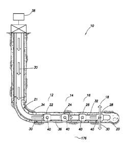
Representatively illustrated in FIG. 1 is a well system
10 and associated method which embody principles of the
present invention. The system 10 and method are used to
selectively stimulate multiple sets of one or more intervals
12, 14, 16, 18 of a formation 176 intersected by a wellbore
20.
Each of the interval sets 12, 14, 16, 18 may include
one or more intervals of the formation 176. As depicted in
FIG. 1, there are four of the interval sets 12, 14, 16, 18,
and the wellbore 20 is substantially horizontal in the
intervals, but it should be clearly understood that any
number of intervals may exist, and the wellbore could be
vertical or inclined in any direction, in keeping with the
principles of the invention.
A casing string 21 is installed in the wellbore 20. As
used herein, the term "casing string" is used to indicate
any tubular string which is used to form a protective lining
for a wellbore. Casing strings may be made of any material,
such as steel, polymers, composite materials, etc. Casing
strings may be jointed, segmented or continuous. Typically,
casing strings are sealed to the surrounding formation using
CA 02704834 2010-05-04
WO 2009/070175 PCT/US2007/086132
- 6 -
cement or another hardenable substance (such as epoxies,
etc.), or by using packers or other sealing materials, in
order to prevent or isolate longitudinal fluid communication
through an annulus formed between the casing string and the
wellbore.
The casing string 21 depicted in FIG. 1 includes four
valves 22, 24, 26, 28 interconnected therein. Thus, the
valves 22, 24, 26, 28 are part of the casing string 21, and
are longitudinally spaced apart along the casing string.
Preferably each of the valves 22, 24, 26, 28
corresponds to one of the interval sets 12, 14, 16, 18 and
is positioned in the wellbore 20 opposite the corresponding
interval. However, it should be understood that any number
of valves may be used in keeping with the principles of the
invention, and it is not necessary for a single valve to
correspond to, or be positioned opposite, a single interval.
For example, multiple valves could correspond to, and be
positioned opposite, a single interval, and a single valve
could correspond to, and be positioned opposite, multiple
intervals.
Each of the valves 22, 24, 26, 28 is selectively
operable to permit and prevent fluid flow between an
interior and exterior of the casing string 21. The valves
22, 24, 26, 28 could also control flow between the interior
and exterior of the casing string 21 by variably choking or
otherwise regulating such flow.
With the valves 22, 24, 26, 28 positioned opposite the
respective interval sets 12, 14, 16, 18 as depicted in FIG.
1, the valves may also be used to selectively control flow
between the interior of the casing string 21 and each of the
interval sets. In this manner, each of the interval sets
12, 14, 16, 18 may be selectively stimulated by flowing
CA 02704834 2010-05-04
WO 2009/070175 PCT/US2007/086132
- 7 -
stimulation fluid 30 through the casing string 21 and
through any of the open valves into the corresponding
interval sets.
As used herein, the term "stimulation fluid" is used to
indicate any fluid, or combination of fluids, which is
injected into a formation or interval set to increase a rate
of fluid flow through the formation or interval set. For
example, a stimulation fluid might be used to fracture the
formation, to deliver proppant to fractures in the
formation, to acidize the formation, to heat the formation,
or to otherwise increase the mobility of fluid in the
formation. Stimulation fluid may include various
components, such as gels, proppants, breakers, etc.
As depicted in FIG. 1, the stimulation fluid 30 is
being delivered to the interval set 18 via the open valve
28. In this manner, the interval set 18 can be selectively
stimulated, such as by fracturing, acidizing, etc.
The interval set 18 is isolated from the interval set
16 in the wellbore 20 by cement 32 placed in an annulus 34
between the casing string 21 and the wellbore. The cement
32 prevents the stimulation fluid 30 from being flowed to
the interval set 16 via the wellbore 20 when stimulation of
the interval set 16 is not desired. The cement 32 isolates
each of the interval sets 12, 14, 16, 18 from each other in
the wellbore 20.
As used herein, the term "cement" is used to indicate a
hardenable sealing substance which is initially sufficiently
fluid to be flowed into a cavity in a wellbore, but which
subsequently hardens or "sets up" so that it seals off the
cavity. Conventional cementitious materials harden when
they are hydrated. Other types of cements (such as epoxies
or other polymers) may harden due to passage of time,
CA 02704834 2010-05-04
WO 2009/070175 PCT/US2007/086132
- 8 -
application of heat, combination of certain chemical
components, etc.
Each of the valves 22, 24, 26, 28 has one or more
openings 40 for providing fluid communication through a
sidewall of the valve. It is contemplated that the cement
32 could prevent flow between the openings 40 and the
interval sets 12, 14, 16, 18 after the cement has hardened,
and so various measures may be used to either prevent the
cement from blocking this flow, or to remove the cement from
the openings, and from between the openings and the interval
sets. For example, the cement 32 could be a soluble cement
(such as an acid soluble cement), and the cement in the
openings 40 and between the openings and the interval sets
12, 14, 16, 18 could be dissolved by a suitable solvent in
order to permit the stimulation fluid 30 to flow into the
interval sets. The stimulation fluid 30 itself could be the
solvent.
In the well system 10, the valve 28 is opened after the
cementing operation, that is, after the cement 32 has
hardened to seal off the annulus 34 between the interval
sets 12, 14, 16, 18. The stimulation fluid 30 is then
pumped through the casing string 21 and into the interval
set 18.
The valve 28 is then closed, and the next valve 26 is
opened. The stimulation fluid 30 is then pumped through the
casing string 21 and into the interval set 16.
The valve 26 is then closed, and the next valve 24 is
opened. The stimulation fluid 30 is then pumped through the
casing string 21 and into the interval set 14.
The valve 24 is then closed, and the next valve 22 is
opened. The stimulation fluid 30 is then pumped through the
casing string 21 and into the interval set 12.
CA 02704834 2010-05-04
WO 2009/070175 PCT/US2007/086132
- 9 -
Thus, the valves 22, 24, 26, 28 are sequentially opened
and then closed to thereby permit sequential stimulation of
the corresponding interval sets 12, 14, 16, 18. Note that
the valves 22, 24, 26, 28 may be opened and closed in any
order, in keeping with the principles of the invention.
In a desirable feature of the well system 10 and
associated method, the valves 22, 24, 26, 28 may be opened
and closed as many times as is desired, the valves may be
opened and closed after the cementing operation, the valves
may be opened and closed without requiring any intervention
into the casing string 21, the valves may be opened and
closed without installing any balls or other plugging
devices in the casing string, and the valves may be opened
and closed without applying pressure to the casing string.
Instead, the valves 22, 24, 26, 28 are selectively and
sequentially operable via one or more lines 36 which are
preferably installed along with the casing string 21. In
addition, the lines 36 are preferably installed external to
the casing string 21, so that they do not obstruct the
interior of the casing string, but this is not necessary in
keeping with the principles of the invention. Note that, as
depicted in FIG. 1, the lines 36 are cemented in the annulus
34 when the casing string 21 is cemented in the wellbore 20.
The lines 36 are connected to each of the valves 22,
24, 26, 28 to control operation of the valves. Preferably,
the lines 36 are hydraulic lines for delivering pressurized
fluid to the valves 22, 24, 26, 28, but other types of lines
(such as electrical, optical fiber, etc.) could be used if
desired.
The lines 36 are connected to a control system 38 at a
remote location (such as the earth's surface, sea floor,
floating rig, etc.). In this manner, operation of the
CA 02704834 2010-05-04
WO 2009/070175 PCT/US2007/086132
- 10 -
valves 22, 24, 26, 28 can be controlled from the remote
location via the lines 36, without requiring intervention
into the casing string 21.
After the stimulation operation, it may be desired to
test the interval sets 12, 14, 16, 18 to determine, for
example, post-stimulation permeability, productivity,
injectivity, etc. An individual interval set can be tested
by opening its corresponding one of the valves 22, 24, 26,
28 while the other valves are closed.
Formation tests, such as buildup and drawdown tests,
can be performed for each interval set 12, 14, 16, 18 by
selectively opening and closing the corresponding one of the
valves 22, 24, 26, 28 while the other valves are closed.
Instruments, such as pressure and temperature sensors, may
be included with the casing string 21 to perform downhole
measurements during these tests.
The valves 22, 24, 26, 28 may also be useful during
production to control the rate of production from each
interval set. For example, if interval set 18 should begin
to produce water, the corresponding valve 28 could be
closed, or flow through the valve could be choked, to reduce
the production of water.
If the well is an injection well, the valves 22, 24,
26, 28 may be useful to control placement of an injected
fluid (such as water, gas, steam, etc.) into the
corresponding interval sets 12, 14, 16, 18. A waterflood,
steamfront, oil-gas interface, or other injection profile
may be manipulated by controlling the opening, closing or
choking of fluid flow through the valves 22, 24, 26, 28.
During the formation tests, completion operations,
production operations, etc., when formation fluid is flowed
into the casing string 21, the valves 22, 24, 26, 28 include
CA 02704834 2010-05-04
WO 2009/070175 PCT/US2007/086132
- 11 -
another desirable feature, which provides for filtering the
formation fluid so that proppant, formation fines, or other
debris, particulate matter, etc. is not produced into the
casing string. Specifically, each of the valves 22, 24, 26,
28 has another configuration in which the valve can be
operated to selectively prevent and filter flow through the
opening 40.
Each of the valves 22, 24, 26, 28 can be selectively
configured as desired using the lines 36 and control system
38. Thus, the valves 22, 24, 26, 28 are configurable from a
remote location, without requiring any intervention into the
casing string 21, and without requiring that pressure be
applied to the casing string.
Referring additionally now to FIG. 2, another well
system 170 and associated method incorporating principles of
the invention are representatively illustrated. The well
system 170 is similar in some respects to the well system 10
described above, and so similar elements have been indicated
in FIG. 2 using the same reference numbers.
The well system 170 includes two wellbores 172, 174.
Preferably, the wellbore 174 is positioned vertically deeper
in the formation 176 than the wellbore 172. In the example
depicted in FIG. 2, the wellbore 172 is directly vertically
above the wellbore 174, but this is not necessary in keeping
with the principles of the invention.
A set of valves 24, 26, 28 and lines 36 is installed in
each of the wellbores 172, 174. The valves 24, 26, 28 are
preferably interconnected in tubular strings 178, 180 which
are installed in respective perforated liners 182, 184
positioned in open hole portions of the respective wellbores
172, 174. Although only three of the valves 24, 26, 28 are
CA 02704834 2010-05-04
WO 2009/070175 PCT/US2007/086132
- 12 -
depicted in each wellbore in FIG. 2, any number of valves
may be used in keeping with the principles of the invention.
The interval sets 14, 16, 18 are isolated from each
other in an annulus 186 between the perforated liner 182 and
the wellbore 172, and in an annulus 188 between the
perforated liner 184 and the wellbore 174, using a sealing
material 190 placed in each annulus. The sealing material
190 could be any type of sealing material (such as swellable
elastomer, hardenable cement, selective plugging material,
etc.), or more conventional packers could be used in place
of the sealing material.
The interval sets 14, 16, 18 are isolated from each
other in an annulus 192 between the tubular string 178 and
the liner 182, and in an annulus 194 between the tubular
string 180 and the liner 184, by packers 196.
In the well system 170, steam is injected into the
interval sets 14, 16, 18 of the formation 176 via the valves
24, 26, 28 in the wellbore 172, and formation fluid is
received from the formation into the valves 24, 26, 28 in
the wellbore 174. Steam injected into the interval sets 14,
16, 18 is represented in FIG. 2 by respective arrows 198a,
198b, 198c, and formation fluid produced from the interval
sets is represented in FIG. 2 by respective arrows 200a,
200b, 200c.
The valves 24, 26, 28 in the wellbores 172, 174 are
used to control an interface profile 202 between the steam
198a-c and the formation fluid 200a-c. By controlling the
amount of steam injected into each interval set, and the
amount of formation fluid produced from each interval set, a
shape of the profile 202 can also be controlled.
For example, if the steam is advancing too rapidly in
one of the interval sets (as depicted in FIG. 2 by the dip
CA 02704834 2010-05-04
WO 2009/070175 PCT/US2007/086132
- 13 -
in the profile 202 in the interval set 16), the steam
injected into that interval set may be shut off or choked,
or production from that interval set may be shut off or
choked, to thereby prevent steam breakthrough into the
wellbore 174, or at least to achieve a desired shape of the
interface profile.
In the example of FIG. 2, the valve 26 in the wellbore
172 could be selectively closed or choked to stop or reduce
the flow of the steam 198b into the interval set 16.
Alternatively, or in addition, the valve 26 in the wellbore
174 could be selectively closed or choked to stop or reduce
production of the formation fluid 200b from the interval set
16.
For steam injection purposes in the wellbore 172, the
valves 24, 26, 28 (as well as the seal material 190 and
packers 196) should preferably be provided with appropriate
heat resistant materials and constructed to withstand large
temperature variations. For example, the packers 196 in the
wellbore 172 could be of the type known as ring seal
packers.
The valves 24, 26, 28 in the wellbore 174 may be
configured to permit filtering of the fluid 200 during
formation testing, completion and/or production operations.
The valves 24, 26, 28 are preferably selectively operable
between closed and filtering positions, in order to reduce
or eliminate production of formation fines, particulate
matter, proppant, debris, etc. from the formation 176, and
also to achieve a desired shape of the interface profile
202.
An enlarged scale schematic cross-sectional view of a
valve 80 which may be used for any of the valves 22, 24, 26,
28 in the well system 10 and/or 170 is representatively
CA 02704834 2010-05-04
WO 2009/070175 PCT/US2007/086132
- 14 -
illustrated in FIGS. 3A-E. The valve 80 may be used in
other well systems in keeping with the principles of the
invention.
The valve 80 is of the type known to those skilled in
the art as a sliding sleeve valve, since it includes a
closure member 82 in the form of a sleeve reciprocably
displaceable relative to a housing assembly 84 to thereby
selectively permit and prevent flow through openings 86
formed through a sidewall of the housing assembly. The
closure member 82 is part of a closure assembly 78 which can
also be used to selectively prevent and filter flow through
the openings 86, as described more fully below.
The valve 80 is specially constructed for use in well
systems and methods (such as the well system 10 and method
of FIG. 1) in which the valve is to be operated after being
cemented in a wellbore. Specifically, openings 88 formed
through a sidewall of the closure member 82 are isolated
from the interior and exterior of the valve 80 where cement
is present during the cementing operation. The valve 80 is
preferably closed during the cementing operation, as
depicted in FIGS. 3A-E.
Although use of the valve 80 in the well system 10 is
described (in which the valve is cemented in a wellbore), it
should be clearly understood that the valve 80 is also
suitable for use in well systems and methods (such as the
well system 170 and method of FIG. 2) in which the valve is
not cemented in a wellbore.
When it is desired to open the valve 80, the closure
member 82 is displaced upward, thereby aligning the openings
86, 88 and permitting fluid communication between the
interior and exterior of the housing assembly 84. The
closure member 82 is displaced in the housing assembly 84 by
CA 02704834 2010-05-04
WO 2009/070175 PCT/US2007/086132
- 15 -
means of pressure delivered via lines 36a, 36b externally
connected to the valve 80.
The line 36a is in communication with a chamber 92, and
the line 36b is in communication with a chamber 94, in the
housing assembly 84. The lines 36a, 36b can be included in
the lines 36 in the systems 10, 170 described above. A
protective housing 90 is preferably used to prevent damage
to the lines 36.
Pistons 96, 98 on the closure assembly 78 are exposed
to pressure in the respective chambers 92, 94. In a first
configuration of the valve 80, when pressure in the chamber
94 exceeds pressure in the chamber 92, the closure assembly
78 is biased by this pressure differential to displace
upwardly to its open position. When pressure in the chamber
92 exceeds pressure in the chamber 94, the closure assembly
78 is biased by this pressure differential to displace
downwardly to its closed position.
Note that, when the closure assembly 78 displaces
between its open and closed positions (in either direction),
the closure assembly is displacing into one of the chambers
92, 94, which are filled with clean fluid. Thus, no debris,
sand, cement, etc. has to be displaced when the closure
member 82 is displaced.
This is true even after the valve 80 has been cemented
in the wellbore 20 in the well system 10. Although cement
may enter the openings 86 in the outer housing 84 when the
closure member 82 is in its closed position, this cement
does not have to be displaced when the closure member is
displaced to its open position.
An additional beneficial feature of the valve 80 is
that the chambers 92, 94 and pistons 96, 98 are positioned
straddling the openings 86, 88, so that a compact
CA 02704834 2010-05-04
WO 2009/070175 PCT/US2007/086132
- 16 -
construction of the valve is achieved. For example, the
valve 80 can have a reduced wall thickness and greater flow
area as compared to other designs. This provides both a
functional and an economic benefit.
A shoulder 100 at an upper end of the chamber 92 limits
upward displacement of the closure assembly 78 in the first
configuration of the valve 80. Another shoulder 76 formed
on an inner mandrel 74 of the valve 80 limits downward
displacement of the closure assembly 78.
A ring 72 is carried at a lower end of the closure
assembly 78, and is secured in place with shear screws 70.
The ring 72 abuts the shoulder 76 to prevent further
downward displacement of the closure assembly 78 in the
first configuration of the valve 80.
However, when it is desired to operate the valve 80 to
its second configuration, pressure in the chamber 92 may be
increased (or pressure in the chamber 94 may be decreased)
to thereby apply a predetermined pressure differential
across the pistons 96, 98 to shear the shear screws 70 and
permit the closure assembly 78 to displace further downward.
After the shear screws 70 have been sheared, downward
displacement of the closure assembly 78 is limited by a
shoulder 68 at a lower end of the chamber 94.
Another effect of shearing the screws 70 and downwardly
displacing the closure assembly 78 is that an internal
latching profile 66 on the closure assembly will be
positioned below the upper ends of latching collets 64.
Each of the collets 64 has an external latching profile 62
formed thereon for latching engagement with the internal
profile 66.
Once the internal profile 66 has displaced downward
past the external profiles 62, the engagement between the
CA 02704834 2010-05-04
WO 2009/070175 PCT/US2007/086132
- 17 -
profiles will prevent the closure assembly 78 from
displacing upwardly beyond the collets 64. In other words,
the point of engagement between the profiles 62, 66 becomes
a new limit for upward displacement of the closure assembly
78.
When the profiles 62, 66 are engaged at the upper limit
of displacement of the closure assembly 78 in this second
configuration of the valve 80, the closure member 82 is
positioned opposite the openings 86, and flow through the
openings is prevented. This position of the closure
assembly 78 is achieved by increasing pressure in the
chamber 94 relative to pressure in the chamber 92 to
upwardly displace the closure assembly.
When the closure assembly 78 is downwardly displaced to
abut the shoulder 68, a filter 60 will be positioned
opposite the openings 86. In this position, fluid which
flows through the openings 86 will be filtered by the filter
60. Thus, in formation testing, completion, production
operations, etc., the filter 60 can prevent formation fines,
proppant, debris and/or particulate matter from flowing into
the casing string 21 from the formation 176.
This position of the closure assembly 78 (with the
filter 60 positioned opposite the openings 86) is achieved
by increasing pressure in the chamber 92 relative to
pressure in the chamber 94 to downwardly displace the
closure assembly. If it is desired to close the valve 80
and thereby prevent flow through the openings 86, pressure
in the chamber 94 may be again increased relative to
pressure in the chamber 92 to upwardly displace the closure
assembly 78 (until the profiles 62, 66 engage) and position
the closure member 82 opposite the openings 86.
CA 02704834 2010-05-04
WO 2009/070175 PCT/US2007/086132
- 18 -
Thus, in the first configuration of the valve 80 (prior
to shearing the screws 70 and displacing the internal
profile 66 downward past the external profiles 62), the
valve is repeatedly operable between open and closed
positions, and in the second configuration of the valve
(after shearing the screws 70 and displacing the internal
profile 66 downward past the external profiles 62), the
valve is repeatedly operable between closed and filtering
positions.
The filter 60 may be any type of filter or screen
capable of filtering proppant, formation fines, debris,
particulate matter, etc. from the formation fluid 200. For
example, the filter 60 could be a sand control screen, a
wire-wrapped screen, a wire mesh screen, a sintered screen,
a pre-packed screen, a woven screen, small perforations,
narrow slots, or any other type or combination of filters.
The capability of closing the valve 80 when it is in
the second configuration can be useful in stimulation
operations (to enable selective stimulation of different
interval sets 12, 14, 16, 18) and in formation testing,
completion and production operations to control flow of the
fluid 200 from the formation 176. For example, in the well
system 170, closing one or more of the valves 24, 26, 28 is
useful for controlling the shape of the interface profile
202 during production operations.
Various different systems and methods may be used for
controlling operation of the valve 80. Suitable systems and
methods are described in International Application No.
PCT/US07/61031, filed January 25, 2007, the entire
disclosure of which is incorporated herein by this
reference. The control systems and methods described in the
incorporated application are especially suited for remotely
CA 02704834 2010-05-04
WO 2009/070175 PCT/US2007/086132
- 19 -
controlling operation of multiple valves 22, 24, 26, 28
interconnected in a casing string 21.
Seals used in the valve 80 may be similar to the seals
described in International Application No. PCT/US07/60648,
filed January 17, 2007, the entire disclosure of which is
incorporated herein by this reference. The seals described
in the incorporated application are especially suited for
high temperature applications.
It may now be fully appreciated that the present
invention provides many benefits over prior well systems and
methods for selectively stimulating wells and controlling
flow in wells. Sequential and selective control of multiple
valves is provided, without requiring intervention into a
casing or other tubular string, and certain valves are
provided which are particularly suited for being cemented
along with a casing string, or use in high temperature
environments, etc.
Specifically, the well systems 10, 170 described above
may include at least one valve 80 interconnected in a casing
string 21, the valve being selectively configurable between
first and second configurations via one or more lines 36
external to the casing string 21. The valve 80 in the first
configuration is operable to selectively permit and prevent
fluid flow between an exterior and an interior of the casing
string 21. The valve 80 in the second configuration is
operable to selectively filter and prevent fluid flow
between the exterior and interior of the casing string 21.
The valve 80 may be selectively configurable between
the first and second configurations in response to pressure
manipulation on the one or more lines 36. The valve 80 may
be placed in the second configuration in response to a
CA 02704834 2010-05-04
WO 2009/070175 PCT/US2007/086132
- 20 -
predetermined pressure being applied to at least one of the
lines 36.
In the first configuration, a closure member 82 of the
valve 80 may be selectively displaceable between a first
position in which flow through an opening 86 of the valve is
blocked and a second position in which flow through the
opening is unblocked. In the second configuration, the
closure member 82 may be selectively displaceable between
the first position and a third position in which a filter 60
is operative to filter fluid flow through the opening 86.
The filter 60 may be attached to the closure member 82 and
may displace with the closure member in the second
configuration.
A valve 80 is also described above for use in a tubular
string 21 in a subterranean well. The valve 80 may include
a closure member 82 displaceable between open and closed
positions to thereby selectively permit and prevent flow
through a sidewall of a housing assembly 84 when the valve
is in a first configuration. The closure member 82 may also
be displaceable between closed and filtering positions to
thereby selectively prevent and filter flow through the
housing assembly 84 sidewall when the valve 80 is in a
second configuration. The valve 80 may be selectively
configurable between the first and second configurations
from a remote location without intervention into the well.
A control system 38 may be operative to manipulate
pressure in one or more lines 36 externally connected to the
valve 80 to select between the first and second
configurations. The closure member 82 may be displaceable
between the open and closed positions in response to a
change in pressure in at least one of the lines 36
externally connected to the valve 80. The closure member 82
CA 02704834 2010-05-04
WO 2009/070175 PCT/US2007/086132
- 21 -
may be displaceable between the closed and filtering
positions in response to a change in pressure in at least
one of the lines 36 externally connected to the valve 80.
In the first configuration, the closure member 82 may
be selectively displaceable between the closed position in
which flow through an opening 86 of the valve 80 is blocked
and the open position in which flow through the opening is
unblocked. In the second configuration, the closure member
82 may be selectively displaceable between the closed
position and the filtering position in which a filter 60 is
operative to filter fluid flow through the opening 86. The
filter 60 may be attached to the closure member 82 and
displace with the closure member in the second
configuration.
A method of selectively stimulating a subterranean
formation 176 is also described above. The method may
include the steps of: positioning a casing string 21 in a
wellbore 20 intersecting the formation 176, the casing
string including at least one valve 80 operable to
selectively permit and prevent fluid flow between an
interior and an exterior of the casing string, the valve
being operable via one or more lines 36 externally connected
to the valve; and for at least one interval set 12, 14, 16,
18 of the formation 176, stimulating the interval set by
opening the valve 80, flowing a stimulation fluid 30 from
the interior of the casing string 21 and into the interval
set, and then configuring the valve to filter fluid 200
which flows from the formation into the casing string.
The method may also include the step of, prior to the
stimulating step, cementing the casing string 21 and lines
36 in the wellbore 20. At least one of the lines 36 may be
CA 02704834 2012-05-01
- 22 -
positioned external to the casing string 21 during the
cementing step.
The valve opening and configuring steps may be
performed by manipulating pressure in at least one of the
lines 36. The valve opening and configuring steps may be
performed without intervention into the casing string 21.
The valve opening and configuring steps may be performed
without application of pressure to the casing string 21.
The method may also include the step of testing the
interval set by opening the valve 80, and flowing a
formation fluid 200 from the interval set and into the
interior of the casing string 21. The testing step may
be performed after the stimulating step.
The method may also include the steps of repeatedly
displacing a closure member 82 of the valve 80 between
open and closed positions in a first configuration of the
valve and then, after the configuring step, repeatedly
displacing the closure member between closed and
filtering positions in a second configuration of the
valve.
Of course, a person skilled in the art would, upon a
careful consideration of the above description of
representative embodiments of the invention, readily
appreciate that many modifications, additions,
substitutions, deletions, and other changes may be made
to the specific embodiments, and such changes are
intended to fall within the appended claims.